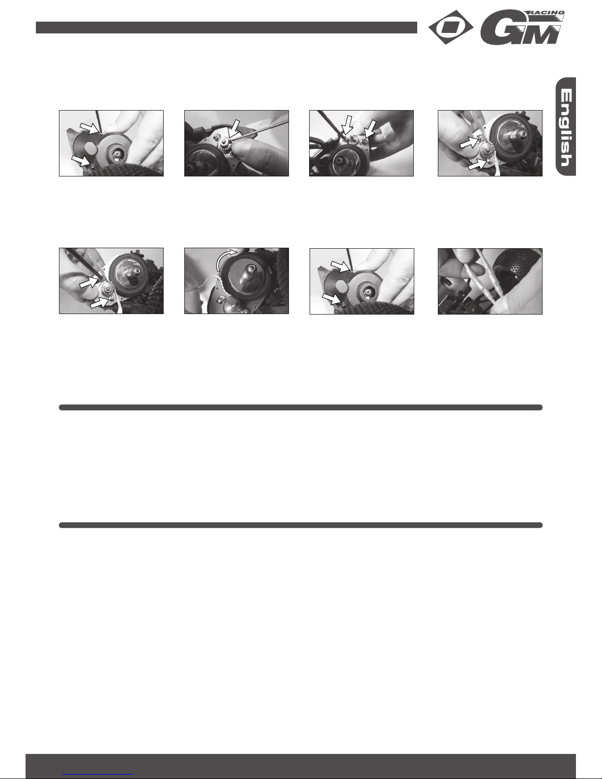
GM-Racing ROADFIGHTER BUGGY User manual

Bedienungsanleitung
Instruction Manual
Manuel d’utilisation
Ersatzteile -
Spare Parts -
Pièces de rechange
Montage -
Assembly -
Montage
Garantie -
Warranty -
Garantie
Deutsch 01-09
English 10-18
Francais 19-27
28-31
32-41
42
GM-Racing 90168.RTR Roadfighter Buggy 2WD
www.gm-racing.de
1/10 2WD RACING BUGGY

SAFTEY PRECAUTIONS
This high-quality RC model should be used with caution and responsibility. Failure to operate this model in a safe and
responsible manner could result in personal and/or property damage. The vehicle should not be taken by children wit-
hout supervision by the parents. GM-Racing/Graupner accepts no responsibility for any loss or damage rising from the
operation, not proper use or misuse of this product or other necessary operations to his product, regardless of whether
they directly, indirectly, on detours, acciden-tally or as a result of its use. So far required by law not compellingly, the
obligation of the company GRAUPNER for the achievement of payment of damages, impossible which reason also al-
ways (inclusive personal injuries, death, damage of buildings as well as damage by turnover or trading loss, by business
interruption or other indirect or direct damages), which are due to the employment of the model. The joint and several
liabilities are limited under all circumstances and each case to the amount, which you actually paid for this model.
This model is controlled by radio signals, with influences beyond your control. This influences can be a temporary•
loss of the ability to control the model, so it is advisable to have a safe distance in all directions to avoid collisions.
Operate your model on open terrain, away from cars, traffic and people.•
Never walk out onto the street, for whatever reason.•
Run your vehicle never with weak batteries.•
Follow carefully to the instructions and warnings for this and any other equipment used by you (Chargers, rechar-•
geable battery packs, etc.).
Keep chemicals, hardware and electrical components out of reach of children.•
Don‘t drive against obstacles, which the model cannot overcome, and stay on full throttle. This can destroy the•
engine, clutch or the transmission!
Don‘t drive in wet grass, puddles or snow, because the electronic equipment (servo, receiver and ESC) is not water-•
proof. If you want to drive in the wet, these parts must be protected waterproof (e.g. by a ballon). Under no circum-
stances the engine should suck water in by the air filter, otherwise the engine can be destroyed immediately.
Plastic is less flexible with cold weather and can break more easily.•
The start-up and the operation of the model take place solely on danger of the owner. Only careful and considered•
handling of the R/C car protects against damages to property and person.
INTRODUCTION
Thank you for buying the Roadfighter Buggy - RTR by GM-Racing. This introduction contains the basic instructions
for the operation of your new vehicle. The Roadfighter Buggy is a great model for RC Beginners, but it also requires a
degree of craftsmanship and with drivers under 14 years, the guidance from the parents. It is important that you read all
instructions and the entire printed collateral, so you can operate without causing unnecessary damage.
Please take a moment to read through it completely before running the model.
These operating instructions are part of this product. They contains important notes to the operation and handling of
the model. Please take this into consideration when you pass on the product to third parties. Neglect of the operating
instructions and the safety instructions lead to expiring the warranty.
GM-Racing and Graupner constantly work on the advancement of all RC cars, engines and remote control systems;
changes of the scope of delivery in form, technology and equipment we must reserve ourselves therefore. Please have
understanding for the fact that from data and illustrations of this operating instructions no requirements can be deri-
ved.
Please keep these instructions for further reference!
GUARANTEE CONDITIONS
The guarantee applies only to such material or operational defects which are present at the time of purchase of the
product. Damage due to wear, overloading, incompetent handling or the use of incorrect accessories is not covered by
the guarantee. The user‘s legal rights and claims under guarantee are not affected by this guarantee. Please check the
product carefully for defects before you make a claim or send the item to us, since we are obliged to make a charge for
our cost if the product is found to be free of faults.
Please follow the safety instructions in your own interest. Read these references also carefully if you are already familiar
with the handling and operation of an RC car.
If you discover a part in the kit, which is defective concerning material or processing, send it - before you used it – back
to us and we will supply replacement to you.
GM-Racing 90168.RTR Roadfighter Buggy 2WD 10

TOOLS REQUIRED
Hex wrench with 1.5 mm, 2 mm (order No. 5775.1,5, 5775.2 and 5775.2,5), Nut driver 5.5mm and 7mm (5783.5,5•
and 5783.7)
Phillips screwdriver PH1, PH2 (5779.1 and 5779.2)•
small needle-nose pliers•
THE REMOTE CONTROL SYSTEM
Here you get an overview of the remote control system of the Roadfighter Buggy and its various functions and settings.
Before the first trip you should be sure all of these functions and settings have read and understood.
Place 8 AA batteries in the battery compartment of the transmitter. Pay attention to the polarity! Now push the antenna
wire of the receiver through the antenna pipe and then put this into the mount at the chassis.
REQUIRES
To operate your new Roadfighter Buggy you will need the following:
8 alkaline AA batteries e.g. No. 3426, or 8 AA battery cells e.g. No. 3621 for transmitter and a suitable charger like•
the Graupner Ultramat series
NiMH battery e.g. No. 98900 GM Power-Pack 7.2V/3600 mAh and a suitable charger like No. 6464 Minilader 3 or•
Ultramat 8, No. 6411
REMOTE CONTROL (TRANSMITTER)
1. ON / OFF switch: Turns the power on/off
2. Steering wheel: Controls direction (left/right) of the model
3. Steering trim: Adjusts the “hands off” direction of the model
4. EPA steering: to set the maximum steering angle
5. Throttle Trigger: Controls speed (forward/brake/reverse) of the model
6. Throttle Trim: Adjusts the motor speed to stop at neutral
7. Control light: indicates adequate battery power
8. Antenna: Transmits signal to the model
The remote control system of the Roadfighter Buggy is optimally adjusted by the factory. Nevertheless you should read
the following chapter, maybe slight adjustments on the remote control should be necessary. For further information to
the remote control system please refer to the enclosed XG-6i 2.0 FHSS manual.
Allen key 1.5, 2, 2.5 mm
Wrench 5.5, 7 mm
Needle-nosed pliers
Phillips-
Srewdriver
PH1, PH2
Antenna
Charging socket
ON/OFF-Switch
Failsafe
AUX-Channel
Steering Trim
Steering wheel
Steering ST.D/R
Battery Case
Throttle Trim
Servo-Reverse
Steering
EPA Steering
EPA Throttle
Servo-Reverse
Throttle
LED ST.D/R
Power LED
Throttle lever
11 GM-Racing 90168.RTR Roadfighter Buggy 2WD

OPERATING THE REMOTE CONTROL
• Run your Roadfighter Buggy never with low transmitter or receiver batteries.
• Never forget switch off the radio after running your vehicle, otherwise the batteries do not last long.
• Turn on the transmitter first, then the vehicle.
• After driving first turn off the vehicle, then the transmitter.
• For optimal use first check the steering and throttle trim positions.
Before the first trip you should be sure all of these functions and settings have read and understood.•
STEERING TRIM
The vehicle should go straight without turning the steering wheel. If not, press the Steering Trim knob above the steering
wheel in the direction needed for the vehicle to go straight.
THROTTLE/BRAKE TRIM
Normally you do not need to adjust anything here, because the neutral point is stored automatically during the ESC
setting. But if the motor turns a little in neutral position, you can correct this with the trim lever below the steering wheel.
Press the lever in the appropriate direction until the motor has stopped and no longer beeps.
ADJUSTING THE STEERING ANGLE
The maximum steering angle can be adjusted with the two buttons on the pistol grip. Pressing the upper button uincre-
ases the the steering angle, by pressing the lower switch the angle is decreased.
Position 1: less control, the vehicle is less sensitive to steering commands of the steering wheel and is therefore easier
to drive - for slippery surfaces.
Position 2: more steering, the vehicle can run tighter turns, but because this it is to drive a little harder - for non-slip
surfaces or when driving on small places.
Caution: make sure that the steering arms (90166.34) do not touch on the C-hubs (90166.35), otherwise the servo
gears will be damaged!
With the servo end point adjustment (EPA), the steering angle can be adjusted separately for both sides, this may be
necessary if the steering angle is different on both sides even after correct steering trim. Read the corresponding section
of the remote control instructions!
Throttle trim
Steering Trim
Steering ST.D/R
GM-Racing 90168.RTR Roadfighter Buggy 2WD 12

CHECKLIST BEFORE YOU START
Check all screws on permanent seat.•
Check all the moving parts to work without binding.•
Check the batteries in the remote control.•
LET THE FUN BEGIN
The Roadfighter Buggy is equipped with an adjustable slipper clutch. With this the acceleration of the car can be adap-
ted to each surface. You can adjust the maximum torque of the motor, the slipper also protects the drive train against
mechanical overloading. The slipper clutch is optimally adjusted by the factory. For slippery surfaces it can be opened
somewhat, therefore remove the cap at the gear cover 90166.9 first. Now loose the M3 nut a little, just until optimal ac-
celeration without wheelspin is reached. In addition push the vehicle backwards and then pull the trigger to full throttle.
There should be no or only very little wheelspin. For a very grippy surface (e.g. asphalt) you can tighten the nut some-
what to improve acceleration. Now install the cap of the gear cover again. Please consider: Tighten the adjusting nut
never completely, the slipper should always be in function, in order to protect the transmission and the drive train.
First, charge the drive battery with a suitable charger. You should also read the instructions of the charger and the safety
precautions listed before charging!. Insert the battery as shown in the figures below.
First switch on the transmitter and second then the vehicle (the switch is located at the rear above the motor). During
switching on do not move the throttle trigger, so that the electronic speed controller can initialize itself correctly. The
speed controller is correctly adjusted, when the red LED is off in neutral position, with throttle or brake engaged the
LED lits. Consider that the speed controller does not go from braking directly into reverse, you must release the throttle
trigger and then go to reverse again.
Before you drive, check the correct function of the vehicle: does it react accurately on your remote control? If not, e.g. the
steering servo trembles or uncontrolled throttle reaction, start driving in no case. Check whether the transmitter batteries
have enough voltage or the car battery is fully charged and change it and/or recharge if necessary.
The run time depends on the surface. In high grass the run time is naturally shorter than on the flat road. When the bat-
tery dumps, first the car runs slower, then the speed controller completely switches off and the vehicle stops.
After driving take the battery out of the vehicle, otherwise uncontrolled starting of the motor may damage the speed
controller or the batteries.
Don‘t drive against obstacles, which the model cannot overcome, and stay on full throttle. This can destroy the engine,
electronic speed controller or the transmission!
Don‘t drive in wet grass or puddles, because the electronic equipment (servo, receiver and speed controller) is not wa-
terproof. If you want to drive in the wet, these parts must be protected waterproof (e.g. by a ballon).
13 GM-Racing 90168.RTR Roadfighter Buggy 2WD

SERVICE
In addition to the already described service work should always try to keep your vehicle in order to prevent wear. If there
is dirt in moving parts, this can affect the performance of the model significantly. Remove dirt or dust with compressed
air, a soft brush and / or with a toothbrush. If possible, try using no solvents, as this can move the dirt in normally inac-
cessible places and thus cause additional wear. We recommend the following simple procedures:
Remove dirt and dust as far as possible with the methods described above.•
Check the car for worn, broken or gripping parts and repair them if necessary.•
Check regularly the fixed seating all screws and tighten them if necessary.•
SERVICE AND REPAIR, SPARE PARTS
For the Roadfighter Buggy all parts are available as spare parts. So if a part is defective or worn, you can identify these
parts with the Exploded view, buy these parts and fix the car yourself with the help of the assembly instruction (pages
32 - 41).
In problem cases, or for questions and repairs, please contact the Service department in your country (see
warranty card on page 42) or:
GRAUPNER-Service, Henriettenstrasse 94-96, D-73230 Kirchheim/Teck,
Tel. +49/1805/472876
SPARE PARTS: at your local hobby shop or online at Graupner spare-parts Shop http://www.graupner-ersatzteilshop.
de/ under order.-nr.: 90168.RTR
GM-Racing 90168.RTR Roadfighter Buggy 2WD 14
MOTOR - PINION CHANGE:
The Roadfighter Buggy is delivered from the factory with a perfect set gear mesh. If you want to change the motor (eg.
for a brushless system) or just exchange the mounted pinion for another, please note the following:
1. Remove the gear by loosing
the two screws.
2. Remove the pinion with a 1.5
mm hex screwdriver.
3. Loosen the motor screws
and and push the motor
away from the gear.
4. Screw the new pinion on the
shaft. Place a narrow strip
of paper between the pinion
and gear. Now slide the pini-
on tight to the main gear.
5. Re-tighten the motor screws. 6. Turn the main gear to remo
ve the paper. Make sure that
the gear can be easily tur-
ned and never get stuck.
7. Fasten the gear cover
again.
8. Plug the motor back on. Note
the polarity and check that the
vehicle moves in the right direc-
tion. If not, change the cables.
Note: the larger the pinion, the higher the speed, but acceleration and run time will be reduced. Also, the motor load is
higher, checking the motor regularly will be necessary!

Problem Possible errors To do
Motor does not run Broken motor wiring Resolder wiring
Battery empty Change or charge battery
Remote control does not function
correctly, throttle trim wrong adjusted
Check Remote control, adjust throttle
trim
Motor not working Change motor
ESC not adjusted properly Check ESC settings
Motor rotates reverse Motor connected wrong Change motor wires
No motor performance Battery almost empty Change or charge battery
Speed control not adjusted properly Adjust ESC
Drivetrain runs heavily Check drivetrain
Drivetrain works loud Check gear mesh
Motor is getting hot Check drivetrain, gear mesh, check
for binding parts
The car is difficult to steer Transmitter batteries empty Change or charge batteries
Steering servo trim not adjusted
properly
Trim steering servo
Interferences Make a short break an then try again
or change crystals
ESC not adjusted properly Check ESC settings
TROUBLESHOOTING
15 GM-Racing 90168.RTR Roadfighter Buggy 2WD
Specifications ESC:
Number of cells NiMH 6 - 7 (6.0 - 7.4 V)
Constant current forward 100 A (200 A ~ 5 sec.)
Constant current reverse 50 A (100 A ~ 5 sec.)
BEC 5.0 V / 2 A (4 A ~ 5 sek.)
Dimensions ca. 42x37x30 mm (w/o wiring)
Receiver connector Graupner/JR
Lenght: 405 mm
Width: 250 mm
Height: 135 mm
Wheelbase: 265 mm
Weight: 1195 g (battery not included)
Ground clearance: 40 mm
Wheel diameter: 85 mm
Gear ratio: 1:8.8 (brushed)
1:9.6 (brushless)
Motor: 540 type brushed
Radio System: GM-Racing XG-6i 2.0 FHSS Sport Spec 2.4 GHz
SPECIFICATIONS ROADFIGHTER BUGGY

DAMPING
The four oil-filled shocks of this GM-Racing car have largest influence on its handling. Whenever you re-assemble these
shock absorbers again: Do it carefully! Assemble the absorbers always in pairs (in front and in the back). If one of the
front shocks should be somewhat softer or harder than the other one, the vehicle will steer along curves in one direction
different than in the other one. The same is valid for the rear shock absorbers. The absorption should be a bit harder in
the front than in the back to achieve a good-natured handling.
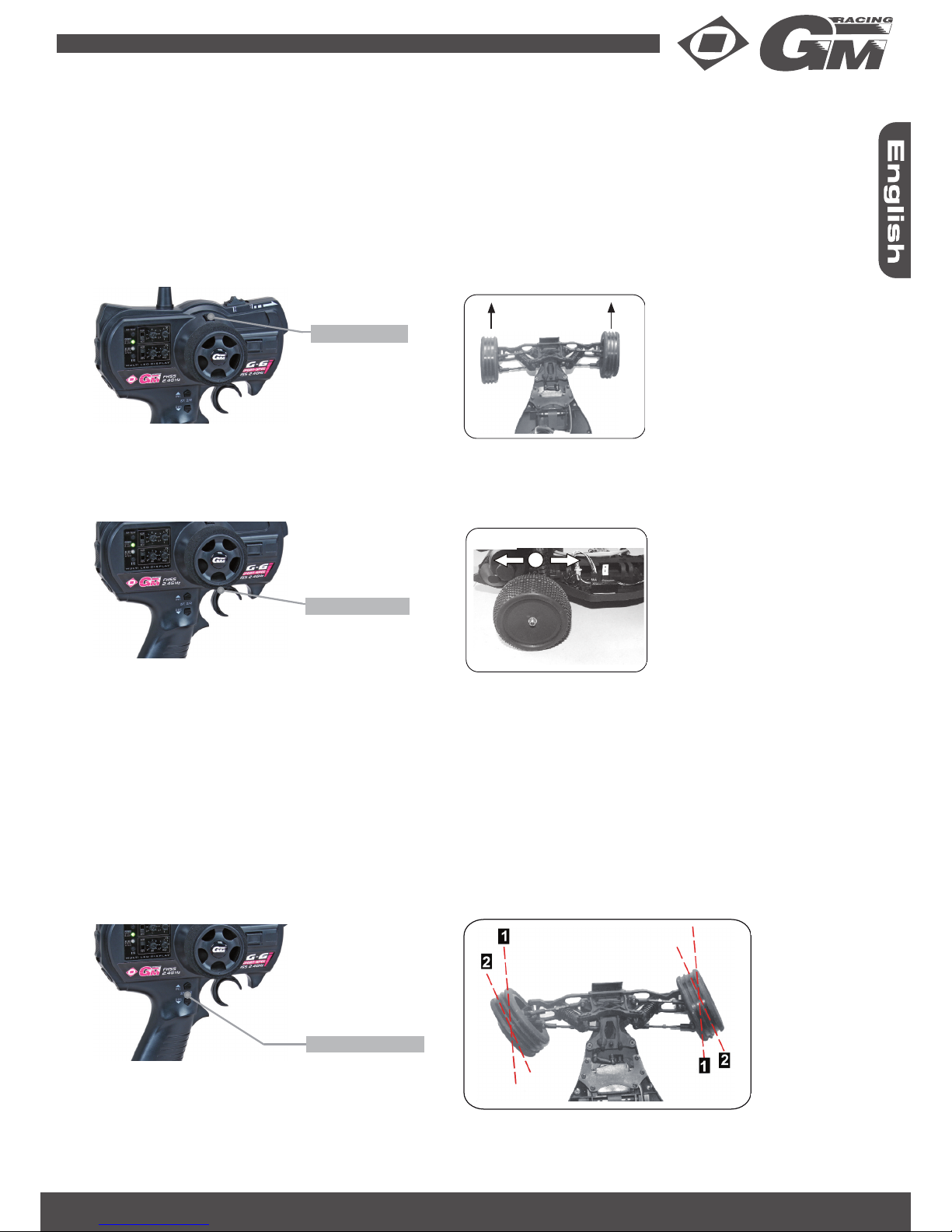
The ride height of the model is very important. It is to be adjusted in such a way that the arms of the front and rear
suspension go back to parallel to the ground, if you raise the model from the ground and then release it. This ensures
sufficient movement of the suspension in both directions (compression and releasing). If the car does not go back the
correct driving height, the feather/spring seals must be adjusted accordingly again.
It is normally best to begin with a softer shock oil and then try a harder oil. If the chassis jumps excessively strong on a
rough track, you should use a softer oil. If the tires take off with the same impacts from the surface of the track, the oil is
too thick. In this case a thinner oil is to be used, so the suspension reacts faster. Thus it is reached that the tire remains
as much as possible in contact with the surface of the course.
The shock absorbers can also affect the steering behavior of your car. This can be regulated by an appropriate soft or
hard adjustment of the front and rear suspension. The firmness is affected by feather/spring characteristic, thickness of
the oil and the inclination of the shock absorbers, as well as the combination of these three factors. With a soft rear end
the traction power (road grip) is improved, the steering more weakly. The handling of the vehicle can be foreseen here
more easily, because this is inclined in curves to understeer, i.e. pushes to the outside of the curve. If the rear suspensi-
on is too hard, the steering effect is stronger, but requires more skill by the driver, in order to avoid spinning the vehicle
around. During softer adjustment of the front suspension the guidance effect is strengthened and turned around, decre-
ased during harder attitude. Within the correct absorption range - chassis jump and hop the wheels - there is a narrow
fine tuning range, in which you can adjust the firmness of front and rear suspension. This is a tricky attitude, which must
be made by very small changes in the viscosity of the oil.
WEIGHT DISTRIBUTION
Always remember with adjusting the shock absorbers that the correct weight distribution is from great importance, so
that the GM-Racing car can show a perfect handling.
Preload the rear shock-absorbers on the right and on the left side with the same amount of tension directly and check
this for example with the help of a Tweak-board. The chassis tweak is adjusted if necessary by easily preload the springs
on the front axle.
With reducing the speed in the curve entrance the weight shifts on the two front wheels and/or - tire, with maximum
effect on the steering. On the opposite with accelerating the weight is shifted on the two rear tires, for maximum traction
power.
The more softly the suspension is, the more the weight transfer affects the handling of the car. For this reason it is
appropriate to make the suspension as fast responding as possible, but not so softly that the absorption becomes inef-
fective. Between these two extremes the „midway“ is the best, which you can determine on the own race track only by
the practical attempt.
ADJUSTING THE WHEELS
First: make sure that the steering trim at the transmitter is in neutral position. Then adjust the servo-saver and the tie
rods in such a way that the wheels stand exactly in straight line adjustment. Thus it is guaranteed that the steering travel
is the same on both sides.
The toe-in is a skew of the wheels in driving direction (seen from above). This adjustment of the front wheels is important
for the handling of the vehicle. The travelling straight ahead of the model is improved by a small angle. The toe-in can
be adjusted by rotating of the right/left- threaded rods (tie rods) without disassembly of the ball joints. The tie rods are to
be adjusted in such a way that the toe-in amounts to approx. 0°-1°. It should be paid attention to the fact that the right
and left tie rod is equivalent long. At the beginning of driving with the car adjust all four wheels in such a way that they
stand with normal driving height perpendicularly to the ground. For examination hold a rectangle or an indication triangle
against the wheel, so that the wheels are adjusted exactly. When pressing on the suspension you will determine that the
wheels gets a little negative camber (spreading).
The reason for this is that you want to reduce the positive camber of the outside wheels when going into the curve. Thus
the bearing surface and the traction power of the outside tires and concomitantly the speed are increased when driving
through curves. The change of the negative camber (thus spreading) with the rear wheels is however the cause for a
reduction of the bearing surface of the tires of the rear wheels when pressing the suspension down by accelerating.
If your track has more straights than curves, it will possibly turn out that an additional decrease (positive) of the camber
is not necessary with driving along curves.
GM-Racing 90168.RTR Roadfighter Buggy 2WD 16

In this case it recommends to leave the rear wheels within the entire range of the suspension perpendicularly to the
ground. A small enlargement of spreading (negative fall) at the front suspension will improve the steering control of the
car when squeezing the suspension together. But: In the case of a too large change of the camber the bearing surface
of the tire is strongly made smaller.
WAYS TO IMPROVE YOUR DRIVING
The improvement of your driving skills is extraordinarily important, often however unconsidered aspect with R/C driving.
Consistent „smooth“ driving is the key to understand the effect of even smallest setup changes of your car on its hand-
ling. Here a few hints, which will help to driver faster from run to run.
Avoid collisions1.
The winner of a race is often not the fastest vehicle, but that, which is involved fewest into accidents and which ma-
kes the fewest driving errors. Drive carefully in places, in which vehicles become wedged into one another again and
again.
Stay away from vehicles, which are slower or are controlled by inexperienced drivers. If you drive near too closely at
their rear end, such drivers can run scared, make an accident and entangle you therein. You lose less time, if you wait
for the fact that a slow vehicle is passed through a critical curve, as if you are entangled into an accident and have to
wait that the (hopefully attentive) track marshal helps your car. Apart from the fact that such an accident costs time, it
can cause also a damage of your vehicle, whereby you are ruled out possibly completely from running. Remember that
a collision with a wall with a maximum speed of 60 – 80 km/h corresponds to a case of a fall from your car of the roof of
a house. If the manufacturer wanted to make an R/C car absolutely indestructible, he would become much too heavy,
that the car would be still competitive. The better solution is called “drive carefully!“
Driving through a curve correctly2.
You drive through a curve correctly, if you start from the outside, then to the inside at the apex of the curve and then go
again to the outside.
If more closely traffic on the course prevails, you will not always be able to drive the racing line in the curves. In these
cases decrease the speed and try to drive as closely as possible along the inside of the curve. Colliding vehicles be-
cause of close traffic are normally pushed of the curve. Also track conditions can force you to change your racing line in
the curves. It is often better to drive around holes and peaks, instead of driving over it, only to follow the racing line.
With the entering into a curve reduce the speed, on the exit accelerate your vehicle. Reduce the throttle with the entran-
ce gradually. Thereby you shift the weight of the car on the front wheels and improve the steering performance of the
car (see also chapter „damping“). Do not accelerate too strongly, because otherwise your R/C car slides to the outside
of the track, or drives, under-steering, to the external wall. Smooth, consistent throttle manipulation and steering is the
key to fast driving through curves. „Burnouts“ and full braking increase the wear of the car, increase the danger of an
accident and result in a lower average speed. It is important that the R/C car always rolls! If you try to drive completely
smooth and consistent your lap-times will improve naturally.
GM-Racing/GRAUPNER GmbH & CO. Kg D-73230 KIRCHHEIM/TECK GERMANY
Subject to change! /We reserve the right to introduce modifications
17 GM-Racing 90168.RTR Roadfighter Buggy 2WD

EG DECLARATION OF CONFORMITY:
We hereby declare that the following product:
Electr. Speed controller Roadfighter ST order.-nr. 90166.64
confirms with the essential protective requirements as laid down in the directive for harmonising the statua-
tory directives of the member states concerning electro-magnetic interference 2004/108/EC.
This product has been tested for electro-magnetic interference in accordance with the following norms:
EN 61000-6-1
EN 61000-6-3
This declaration was produced by
Graupner GmbH & Co. KG
Henriettenstr. 94-96
73230 Kirchheim/Teck
and is valid for the manufacturer / importer of the product
73230 Kirchheim/Teck, den 05.01.2011 Stefan Graupner
Managing Director
ENVIRONMENTAL PROTECTION NOTES
When this product comes to the end of its useful life, you must not dispose of it in the ordinary domestic waste. The
correct method of disposal is to take it to your local collection point for recycling electrical and electronic equipment.
The symbol shown here, which may be found on the product itself, in the operating instructions or on the packaging,
indicates that this is the case.
Individual markings indicate which materials can be recycled and re-used. You can make an important contribution to the protection
of our common environment by re-using the product, recycling the basic materials or recycling redundant equipment in other ways.
Remove batteries from your device and dispose of them at your local collection point for batteries.
In case of R/C models, you have to remove electronic parts like servos, receiver or speed controller from the product in question, and
these parts must be disposed of with a corresponding collection point for electrical scrap.
If you don’t know the location of your nearest disposal centre, please enquire at your local council office.
Important note regarding disposal of dry and rechargeable batteries:
The German Battery Regulation stipulates that every consumer has a legal responsibility to return all used and exhausted dry and
rechargeable batteries.
It is prohibited to dispose of these items using the domestic waste system. Unwanted dry and rechargeable batteries can be sur-
rendered at no charge at your local community collection centre, at our retail outlets, and at any shop where dry and rechargeable
batteries of the same type are sold.
You are entitled to send exhausted batteries to us at the following address:
Graupner GmbH & Co. KG
Service: Gebrauchte Batterien (Used Batteries)
Henriettenstr. 94-96
D-73230 Kirchheim unter Teck
Germany
In so doing you make an important contribution to environmental protection.
Dry and rechargeable batteries which contain harmful materials are marked with the following symbols, which warn that they must not
be discarded using the domestic waste system.
The chemical symbol for the heavy metal is stated under each symbol:
LIABILITY FOR PRINTING ERRORS EXCLUDED! WE RESERVE THE RIGHT TO INTRODUCE MODIFICATIONS!
The newest version of this manual can be found in the Internet under www.graupner.de (No. 90168.RTR)
Battery contains:
1) Cd: Cadmium
2) Hg: Mercury
3) Pb: Lead
Cd Hg Pb
GM-Racing 90168.RTR Roadfighter Buggy 2WD 18

Ersatzteile (1)
Spare Parts
Pièces de rechange
90168.10
Chassis
Chassis
Châssis
90166.2
Chassisvorderteil
Upper deck
Châssis avant
90167.8
Dämpferbrücke vorne + hinten
Front + Rear Shock Tower
Plaque amortisseurs avant/arrière
93808.23
Motoritzel 23 Z. für 540 Motor
Motor Pinion 23T. for 540 motor
Pignon 23 dents pour 540 moteur
90167.10
Untere Querlenker hinten (2)
Rear lower suspension arms
Bras arrière inférieur
90167.9
Untere Querlenker vorne (2)
Front lower suspension arms
Bras avant inférieur
90166.7 90166.8
Querlenkerstifte vorne innen (2)
Front Lower Sus. Hinge Pin inside
Goupille bras avant inférieur
Getriebegehäuse
Gear case
Boîter de transmission
90166.9 90166.10
Getriebeabdeckung
Gear cover
Couvercle de transmission
Motorhalteplatte
Motor Plate
Fixation moteur
90166.11
Slipperplatten mit Slipperscheibe (2)
Adjusting slipper with pads
Rondelle d‘embrayage de patinage
90166.12
Slipperfeder (2)
Slipper adjustment spring
Ressort d‘embrayage
90166.13
Getriebewelle
Gear shaft
Arbre de transmission
90166.14 90166.15
Differenzial/Getriebezahnräder kompl.
Diff. Gears complete set
Pignon de transmission complète
90166.16
Hauptzahnrad 83 Zähne
Main gear 83 T
Pignon 83 dents
90166.17
Differenzialstifte mit Beilagscheiben
Differential pins with shims
Goupilles de differéntiel/rondelles
90166.18
Differenzial komplett m. Kugellagern
Differential complete w/ ball bearings
Differéntiel complète / roulements
90166.19
Motorritzel 23 Z. für Brushless (5mm)
Motor pinion 23 T for brushless
Pignon 23 dents pour brushless
90167.11
Stoßdämpfer vorne komplett (2)
Front shock absorbers
Amortisseurs avant complète
90167.12
Stoßdämpfer hinten komplett (2)
Rear shock absorbers
Amortisseurs arrière complète
90167.17
Stoßdämpferfedern vorne (2)
Front shock springs
Ressort amortisseurs avant
90167.18
Stoßdämpferfedern hinten (2)
Rear shock springs
Ressort amortisseurs arrière
90167.19
Stoßdämpferreparaturset vorne (2)
Front shock repair set
Set de réparer de amortisseurs avant
Querlenkerstifte vorne aussen (2)
Front Lower Sus. Hinge Pin outside
Goupille bras avant extérieur
GM-Racing 90168.RTR Roadfighter Buggy 2WD 28

Ersatzteile (2)
Spare Parts
Pièces de rechange
90167.20
Stoßdämpferreparaturset hinten (2)
Rear shock repair set
Set de réparer de amortisseurs arrière
90167.14
Lenkstangen (2)
Steering rods set
Triangle de direction
90167.13
Obere Querlenker vorne/hinten (2)
Front/Rear upper rods
Bras supérieur avant/arrière
90166.28
Anlenkung Servo
Servo Linkage assembly
Triangle servo - renvoi
90166.29
Radachsen hinten (2)
Rear axles
Arbre de transmission arrière
90166.30
Radachsen vorne (2)
Front axles
Arbre de transmission avant
90168.11
Antriebsknochen hinten Buggy/SC (2)
Rear drive shafts Buggy/SC
Arbre de transmission arrière Buggy/SC
90166.32
Differenzialausgänge (2)
Connecting cups
Sortie de différentiel
90166.33
Radträger hinten (2)
Rear hub carriers
Support de roues arrière
90166.34
Lenkhebel vorne (2)
Steering arms
Renvoi de direction avant
90166.35
Lenkhebelträger vorne (2)
C-mounts
Support renvoi de direction avant
90166.36
Umlenkhebel mit Verbindungsplatte
Steering Mount Assembly
Palonnier servo
90166.37
Querlenkerstifte hinten aussen (2)
Rear Lower Susp. Hinge Pin outside
Goupille bras arrière extérieur
90166.38
Querlenkerstifte hinten innen (2)
Rear Lower Susp. Hinge Pin inside
Goupille bras arrière intérieur
90166.39
Verstärkungsplatte untere Querlenkerstifte
Front lower suspension reinforcing sheet
Renforcement de goupille bras avant
90166.40
Front-/Heckrammer
Front - rear bumper
Jupe de protection avant/arrière
90166.41
Bulkhead vo. + hi. / Halterung Dämpferbrücke
Front + rear bulkhead / Shock Tower Mount
Bulkhead avant/arrière / Support plaque
amortisseur
90166.42
Schalterbefestigung
Switch Mount
Support interrupteur
90168.1 90168.8
Akkuhalterung unten mit Befestigung
Battery holder with pins
Fixation accu avec goupilles
90166.45
Stifte für Lenkhebel (2)
Steering Hub Hinge Pins
Goupilles de renvoi de direction
avant
90166.46
Querlenkerhalter hinten unten (Paar)
Rear suspension pivot block set
Support bras arrière inférieur
90166.47
Beilagscheiben für Lenkhebel
Enforced Pads
Rondelles pour palonnier servo
90168.9
Klammern für Heckflügel
Buggy Wing Pins
Clip de fixation de aileron arrière
Karosserie- und Heckflügelhalterung
Wing Stay and Front Body Post
Support Carrosserie et fixation de aileron
arrière
29 GM-Racing 90168.RTR Roadfighter Buggy 2WD

Ersatzteile (3)
Spare Parts
Pièces de rechange
Vorderräder komplett (2)
Front tires
Pneus avant
Servohalterung + Lenkhebel
Front Top Mount + Servo Arm/Mount
Support Servo + Palonnier de servo
de direction
90166.49
Stoßdämpfer-Kugelköpfe (8)
Shock ball studs
Rotules pour amortisseur
90166.50
Scheiben für Radmitnehmer hinten (4)
Wheel washers
Rondelles pour entraînement roue
arrière
90166.51
Radmitnehmerstifte (8)
Wheel hex pin
Goupilles de roue arrière
95155
Kugellager 3x6x2,5mm
Ball bearing 3x6x2,5mm
Roulement 3x6x2,5mm
95168 95150 90166.52 90166.53
Feder für Servosaver / Befestigung Umlenkhebel
Steering Mount Assembly / Servo saver Spring
Support + Ressort pour Servo saver
90166.54
Kugelköpfe für Lenkung (8)
Turning Linkage Ball Stud
Rotules pour raccordement de
direction
90500.47 90154.17 90166.57
Kugelköpfe 4.8x4.9 mm (8)
Ball studs 4.8x4.9 mm
Rotules 4.8x4.9 mm
90502.76 90503.83
Karosserieklammern (10)
Body-clips
Clip de fixation de carrosserie
90048.81
Stoppmuttern M4 (8)
Lock nut M4
Ecrou auto freine M4
90501.55
Stoppmuttern M3 (6)
Lock nut M3
Ecrou auto freine M3
90120.39
Karosserieunterlagscheiben (12)
Body Post Pad
Rondelle carrosserie
90168.4 90168.3 90168.2
Hinterräder komplett (2)
Rear tires
Pneus arrière
90168.6
Karosserie Roadfighter Buggy gelb
Body Roadfighter Buggy yellow
Carrosserie Roadfighter Buggy jaune
98022
Antennenrohr mit Kappe (6)
Antenna pipe & cap
Tube d‘antenne avec capuchon
90166.62
Schraubensatz komplett
Screw set
Loz de visserie complet
90166.63
Lenkservo (3,2 kg Stellkraft)
Steering servo
Servo
Kugellager 5x10x4mm
Ball bearing 5x10x4mm
Roulement 5x10x4mm
Kugellager 10x15x4mm
Ball bearing 10x15x4mm
Roulement 10x15x4mm
E-Clips 4mm (10)
E-Clips 4mm
E-Clips 4mm
E-Clips 3mm (10)
E-Clips 3mm
E-Clips 3mm
Stoppmuttern M2.5 (8)
Lock nut M2.5
Ecrou auto freine M2.5
Karosserie Roadfighter Buggy rot
Body Roadfighter Buggy red
Carrosserie Roadfighter Buggy rouge
GM-Racing 90168.RTR Roadfighter Buggy 2WD 30

Ersatzteile (4) - Tuning Teile
Spare Parts - Tuning parts
Pièces de rechange - Pièces de tuning
90166.64
Elektr. Fahrtenregler Roadfighter ST
Brushed ESC Roadfighter ST
Variateur electr. Roadfighter ST
90166.67
Brushless Fahrtenregler 90A
Brushless ESC 90A
Variateur electr. Brushless 90A
98900
NiMH-Akku 7.2 V 3600 mAh
NiMH battery 7.2 V 3600 mAh
NiMH accu 7.2 V 3600 mAh
90166.66
540er Motor
540 brushed motor
540 moteur
90166.68
Brushless Motor (3930KV)
Brushless Motor (3930 KV)
Brushless Moteur (3930 KV)
Tuningteile - Tuning parts - Pièces de tuning
90166.100 93808.21
Adjustable Rear Suspension Mount
Querlenkerhalter hinten einstellbar
93808.27 90166.103
90166.104
Motoritzel 21 Z. für 540 Motor
Motor Pinion 21T. for 540 motor
Pignon 21 dents pour 540 moteur
Motoritzel 27 Z. für 540 Motor
Motor Pinion 27T. for 540 motor
Pignon 27 dents pour 540 moteur
Motorritzel 19 Z. für Brushless (5mm)
Motor pinion 19 T for brushless
Pignon 19 dents pour brushless
Motorritzel 21 Z. für Brushless (5mm)
Motor pinion 21 T for brushless
Pignon 21 dents pour brushless
Radträger hinten CNC-Alum. (2)
Rear Hub Carriers CNC (2)
Support de roue arrière CNC
90166.108
Lenkhebelhalter CNC-Alum. (2)
C-Hubs CNC (2)
Support de renvoi de direction CNC Wheelie Bar
CVD-Kardanwellen hinten Buggy/SC (2)
CVD Rear drive shaft Buggy/SC (2)
Arbre de transmission CVD Buggy/SC (2)
90166.105 90166.106 90166.107
Alu-Stoßdämpfer hinten (2)
Rear Shocks full Aluminum (2)
Amortisseurs arrière alum. (2)
Lenkhebel CNC-Alum. (2)
Steering Arms CNC (2)
Renvoi de direction avant CNC (2)
90166.109
Verbindungsplatte Umlenkhebel CNC
Steering Connecting Plate CNC
Connexion de palonnier servo saver CNC
90166.113 90166.111
90166.112
Stahlgetriebe komplett
Metal Gear Complete
Transmission en acier complète
97161
Roadfighter Brushless Conversion Set
Motor/ESC
90168.5
Heckflügel Roadfighter Buggy rot
Wing Roadfighter Buggy red
Aileron arrière Roadfighter Buggy rouge
90168.7
Heckflügel Roadfighter Buggy gelb
Wing Roadfighter Buggy yellow
Aileron arrière Roadfighter Buggy jaune
31 GM-Racing 90168.RTR Roadfighter Buggy 2WD

Silikonöl
Pure Silicon Oil
Huile de silicone
Fett
Grease
Graisse
Für vorne und hinten bauen
Assemble front and rear
Assembler avant et arriére
Für links und rechts bauen
Assemble both left and right side
Assembler à gauche et á droite
Sekundenkleber
CA glue
Colle secunde
Bitte beachten Sie die folgenden Symbole in der Anleitung, sie geben wichtige Hinweise zum Zusammenbau:
Please consider the following symbols in the manual, they give important notes to the assembly:
Veuillez considérer les symboles suivants dans le manuel d‘utilisation, elle donnez des indications importantes à
l‘assemblage:
Montage
Assembly
Assemblage
GM-Racing 90168.RTR Roadfighter Buggy 2WD 32

Montage Stoßdämpfer
Shock Assembly
Assemblage amortisseurs
90167.11
Für links und rechts bauen
Assemble both left and right side
Assembler à gauche et á droite
Für links und rechts bauen
Assemble both left and right side
Assembler à gauche et á droite
Bewegen Sie die Kolbenstange mehrmals lang-
sam auf und ab, bis die Luftblasen entwichen sind.
Move the shaft up and down slowly to remove air
bubbles.
Agiter plusieurs fois la tige de piston lentement
et, jusqu'à ce que les bulles s'échappent soient.
2 mm
90167.12
33 GM-Racing 90168.RTR Roadfighter Buggy 2WD

Montage Lenkung - Differenzial
Steering - Differential Assembly
Assemblage suspension arrière
95155
95155
95155
95155
3x10 mm
3x10 mm
90166.53
90166.36
90166.36
90166.53
90166.53 90166.36
3x10 mm
3x10 mm
95150
90166.18
90166.15
90166.15
90166.15
90166.17
90166.17
90166.17
90166.17
90166.32
90166.32
90166.32
Fett
Grease
Graisse
GM-Racing 90168.RTR Roadfighter Buggy 2WD 34

Montage Getriebe - Motor
Motor - Gearbox Assembly
Assemblage moteur - transmission
90166.10
90166.8
90166.8 95150
95150
95168
95168
95168 95168
90166.51
90500.47
90166.13
90166.12
90166.15
3x30 mm 3x18.5 mm
3x8mm mit Beilagscheibe
with shims
avec rondelles
107.03K
Madenschraube M3
Grub screw M3
Vis sans tête M3
Fett
Grease
Graisse
35 GM-Racing 90168.RTR Roadfighter Buggy 2WD

Montage Vorderachse
Front Assembly
Assemblage avant
90166.54
90166.47
90166.47
90166.35
90166.34
90166.45
Schraube 2.3x4 mm
Screw
Vis
90166.30
90154.17
90166.14
Schraube 2.3x4 mm
Screw
Vis
90166.47
Für links und rechts bauen
Assemble both left and right side
Assembler à gauche et á droite
GM-Racing 90168.RTR Roadfighter Buggy 2WD 36

Montage Lenkung
Steering Assembly
Assemblage tige filetée de direction
Schraube 2.3x4 mm
Screw
Vis
90166.54
Schraube 2.3x4 mm
Screw
Vis
90166.30
90154.17
90166.34
90166.35
90166.47
90166.45
90166.14
90166.47
Für links und rechts bauen
Assemble both left and right side
Assembler à gauche et á droite
37 GM-Racing 90168.RTR Roadfighter Buggy 2WD
This manual suits for next models
1
Table of contents
Other GM-Racing Motorized Toy Car manuals

GM-Racing
GM-Racing Flash 3.0 Nitro User manual

GM-Racing
GM-Racing Flash 3.0 Nitro User manual

GM-Racing
GM-Racing 90191 MRX5 Street Bike User manual

GM-Racing
GM-Racing XXS Series User manual

GM-Racing
GM-Racing 90166.RTR Roadfighter ST User manual

GM-Racing
GM-Racing RADICATOR 3.0 BUGGY User manual

GM-Racing
GM-Racing Radicator Nitro-RTR User manual

GM-Racing
GM-Racing ELEKTROQUAD RTR 1/10 2WD User manual

GM-Racing
GM-Racing Roadfighter SC User manual

GM-Racing
GM-Racing Team Losi Sport Mini-T User manual