GMP GraphicMaster 1600HR User manual

Before operating the unit, please read this manual thoroughly and retain it for future reference.
LEADERS IN LAMINATION TECHNOLOGY
User Guide 2001.05.30
User’s Guide
Operating Instructions
Copyright GMP 2001. All rights reserved. Reproduction by any means of any image in this catalogue is prohibited without the prior consent of GMP and its authroized agent
1600HR,2100HR

TABLE OF CONTENTS
IMPORTANT SAFETY INSTRUCTIONS
INSTALLATION
FEATURES
NAME OF EACH PART
OPERATION OF CONTROL PANEL
HOW TO PERFORM LAMINATION
SAFETY DEVICE
HOW TO PERFORM MOUNTING
LAMINATION GUIDE
CLEANING
TROUBLE-SHOOTING
SPECIFICATIONS
3
6
7
8
11
13
21
22
23
24
24
25
2

This safety message means that you could be burned and your fingers and hands could be
trapped an crushed in the hot rollers.
Die folgenden Warn-Hinweise finden Konnen Sie an diesem Gerat
Warnung : Gefahr eines Elektro-Schocks
Gerat nicht öffnen.
Wenden Sie sich bei Bedarf an unser qualifiziertes
Kundendienst Personal
Dieser Sicherheits-hinweis meint:Sie können ernsthaft verletzt weden, wenn Sie das Gerat offnen,
da Sie mit Hochspannung in Berührung kommen können.
Achtung : Beheizte Walzen
CAUTION : Hot Roller
This safety message means that you could injury yourself if you are not careful.
Dieser Sicherheits-Hinweis meint: Sie können sich bei Berührung der Walzen vervrennen und Thre
Finger in den hei en Walzen gequetscht werden. Kleidung, z. B. Krawatten, Schals, langes Haar,
Schmuck etc. kann von den Walzen erfa t werden und Sie in das Great hineinziehen.
Achtung : scharfe Messerklinge
Dieser Sicherheits-Hinweis meint: Sie können sich verletzen, wenn Sie nicht vorsichog mit der
Schneidevorrichtung umgehen.
CAUTION : Sharp blade.
WARNING :The safety alert symbol precedes each safety message
in this instruction manual. The symbol indicates a potential personal safety hazard
to you or others, as will as product or property damage.
General
Keep hands, long, loose clothing, and articles such as necklaces or ties away from the front of the
hot and pull rollers to avoid entanglement and entrapment. The heat shoe can reach temperatures
over 180 degree C. Avoid contact with the heat shoe during operation or shortly after power has
been removed from the laminator.
Keep hands and fingers away from the path of the sharp edges or table.
An unstable surface may cause the laminator fall resulting in serious bodily injury. Avoid quick
stops, excessive force and uneven floor surfaces when moving the laminator on a cart or stand.
Do not defeat or remove electrical and mechanical safety equipment such as interlocks, shields
and guards. Do not insert objects unsuitable for lamination or expose the equipment to liquids.
Electrical
The laminator should be connected only to a source of power as indicated in therse instructions
and on the serial plate locaated on the rear of the laminator. Contact an electrician should the
attachment plug provided with the laminator not match the receptacles at your location.
WARNING : To guard against injury, the following safety precautions must be observed
in the installation and use of the laminator.
Wichtige Sicherheits - Hinweise
34
D
USA
GB
IMPORTANT SAFETY INSTRUCTIONS
CAUTION
RISK OF ELECTRIC SHOCK
DO NOT OPEN
To prevent fire or shock hazard, do not expose the unit to rain or moisture.
This symbol is intended to alert the user to the presence of uninsulated
“dangerous voltage” whithin the product’s enclosure that may be of
sufficient magnitude to constitute a risk of electric shock to presons.
Dieses Sicherheits-Zeichen markiert einen wichtigen Sicherheits-Hinweis in diesem
Bedienungshandbuch und auch an dem Gerät.Lesen und beachten Sie diese Sicherheits-Hinweise
und die entsprechenden Bedienungsanweisungen sorgfältig.Bewahren Sie diese Hinseise fur
spatere Benutzung auf.Die folgenden Warnungen Können Sie auf dem gerat finden:
D
The safety alert symbol precedes each safety message in this instruction manual and
on the product you will find important safety messages.
Read these messages and instructions carefully. Save these instructions for later use.
The following warnings are found upon this product.
CAUTION : TO REDUCE THE RISK OF ELECTRIC SHOCK.DO NOT REMOVE COVER (BACK).
NO USER SERVICEABLE PARTS INSIDE. REFER SERVICING TO QUALIFIED SERVICEPERSONNEL
This symbol is intended to alert the user to the presence of important
operating and maintenance (servicing) instructions in the literature
accompanying the appliance.
Achtung
Gefahr eines elektrischen Schlages
Gerat bzw. Gëhause nicht offnen
Wichtige Sicherheits - Hinweise
USA
GB
Achtung :
um das Risiko eines elektrischen Schlages zu vermeiden,öffnen Sie mienals das
Gehause eines Gerates. Es befinden sich keine Geräteteile innerhalb, die Sie selber
reparieren order austauschen Konnen. Fragen Sie unbedingt qualifiziertes Service-
Personal. Dieses Symbol weist Sie darauf hin, da Innerhalb dieses geschlossenen Gehauses oder
Gerateteils eine ungeshutzte, gefahrliche Stromspannung existiert, die stark genug sein kann, Sie
durch einen elektrischen Schlag zu gefahrden.
Dieses Symbol weist Sie darauf hin, da ar dieser Stelle der Bedienungsanleitung Wichitige
Bedienungs-oder Service-bzw. Reparatur-Hinweise Vermerkt sind.
WARNING : Electric shock hazard, Do not open.No user serviceable parts inside.
Refer servicing to qualified service personnel.
This safety message means that you could be seriously hurt or killed if you open
the product and expose yourself to hazardous voltage.
Your safety as well as the safety of others is important to GMP. In this instruction manual you will
find important safety messages regarding the product. Read these messages carefully.
The following warnings are found upon this product
USA
GB

5
Upon installation...
1. Set up the unit on a leveled surface after confirming with a device for leveling.
If the operating surface is not leveled, that may cause life of the unit to be shortened.
2. This unit draws a lot of electric current at 400V/50Hz. Please make sure the power
source is with enough capacity and make sure the unit is grounded to prevent statics.
3. The capacity of an air compressor (to be purchased separately) should be at least 3/4HP
Prepareing Power Connection:
Tools needed: Flat Screw Driver or Philips Driver, Stripper
1. Female receptacle matching the 3-phase power plug is supplied with GraphicMaster.
The wire to be connected to the receptacle should be at least 3.5mm2for 1600HR and
6mm2for 2100HR.
2. Strip the jacket off each wire as shown below. The stripped copper core should be
20mm 1mm in length.
Twist the stripped copper core clockwise.
20mm
3. The Wire Connection
Insert Neutral wire and tighten with driver.
Insert L3(T) wire and tighten with driver
Insert L2(S) wire and tighten with driver
Insert L1(R) wire and tighten with driver
Preparing Air Hose Connection
1. Adaptor to be attached to the hose from the air
compressor (not included with laminator)is supplied
with laminator. (The air hose should be 8)
2. Slide back the locking collar and insert the male
adaptor from the laminator side into the female adaptor.
Release the locking collar the lock both adaptors.
Insert the yellow/green wire into the hole by
‘Ground’sign. Use a driver to tighten the wire.
WARNING!
BE EXTREMELY CAREFUL WHEN YOU UNLOCK THE ADAPTORS AS THE AIR
PRESSURE WILL REPEL THE ADAPTORS FROM EACH OTHER WITH GREAT FORCE!
Locking Collar
6
INSTALLATION
Do not operate the laminator with a damaged power supply cord or attachment plug, upon
occurrence of a malfunction, or after the laminator has been damaged, contact GMP’s Technical
Service Department or your dealer/distributor for assistance.
Service : Perform only the routine maintenance procedures referred to in these instructions.
Do not attempt to service or repair the laminator. Disconnect the plug from the receptacle
and contact GMP’s Technical Department or your dealer/distributor when one or more of
the following has been connected.
- The power supply cord or attachment plug is damaged.
- Liquid has been spilled into the laminator.
- The laminator is malfunctioning after being mis-handled.
- Laminator does not operate as described in these instructions.
CAUTION
The recepatcle must be located near the equipment and easily accessible. Disconnect
the attachment plug from the receptacle to which it is connected and keep the power
supply cord in your possession while moving the laminator.
WARNING : die folgenden Sicherheits-Hinweise unbedingt beachten, um sich wahrend der
installatiion und des Gebrauchs des Gerates gegen Verletzungen zu schutzen.
Allgemein :
halten Sie lhre Hände, lamges haar, lackere Kleidüngsstucke und Gegenstände wie Halsketten etc fern von
den vorderen hei en Rollen bzw. den Heizeschuhen, um Verbrennungen, Quetschungen oder Zerstörungen
zu vermeiden.
Der Heizschuh kann Temperaturen bis 180 errichen. Vermeiden Sie deshalb den kontakt wägrend der
Arbeit mit dem Laminator und auch kurz nachdem Sie die Stromzufugrung abgeschaltet haben.
Wenn Sie das Gerät in eine neue Position bewegen, vermeiden Sie unebene Fü Boden, plotzliche Ansto e
und ruckartige Stops. Elne unebener Untergrund kann dazu führen, da das Gerät umfallt und lhnen
korperliche Verte zungen zufügt.
Entfernen oder umgehen Sie incht elektrische oder mechanische Sicherheits-Einrichtungen wie
Schutzschalter und-abdeckungen.
Versuchen Sie keine Objekte, die zum Laminieren ungeeignet sind, in das Gerät einzufuhren.
Bringen Sie Keine Flüssigkeiten oder Feuchtigkeit in Kontakt mit dem Laminator.
Elektrizität :
Der Laminator darf nur mit einer Stromquelle in Kontakt gebracht werden, wie in dieser Anleitung
beschrieben bzw. Wie auf dem Typenschild auf der Rückseite des Gerätes vermerkt.
Verstandigen Sie auf alle Fälle einen Elektriker, wenn der am Gerät angebrachte
Strom-Stecker nicht mit der Strömzufuhrung in lhrëm Gëbaude übereinstimmt.
Vorsicht : Der Stromanschlu mu in der Nahe des Gerätes und jederzeit leicht zugänglich sein.
Wenn Sie das Gerät bewegen, ziehen Sie auf alle Fälle den Stecker aus der
stromzufuhrung und befestigen sie ihn an dem Gerät, damit er nicht beschadigt wird
oder die Bewegung behindert.
Arbeiten Sie niemals einer beschädigten Stromzuführung; setzen Sie sich in diesem Falle
mit dem GMP Kundendienst oder lhrem Handler in Verbindung.
Kundendienst : führen Sie nur routinemä ige Überprüfungs- und Reinigungsarbeiten durch,
wie sie in der Bedienungsanleitung beschrieben sind.
Versuchen Sie nie im Falle einer Betriebsstörung, das Gerät seiber zu reparieren
oder den Fehler zu suchen. Ziehen Sie den Stecker aus der Steckdose und
informieren Sie, - insbesondere in den nachfolgenden Fällen, - das technische
Personal von GMP oder lhrem Händler.
- der Geräte- Strom- Stecker bzw, das Stromkabel sind bexchadigt
- Flüssigkeit ist in den Laminator geraten
- der Laminator hat eine Funktionsstörung nach einem Bedienungsfehler
- der Laminator arbeitet nicht entsperchend den Beschreibungen dieser
Bedienungsanleitung
D

7
NAME OF EACH PART
A
B
C
D
E
F
G
H
I
J
M
K
L
N
A Hot Roller
B Control Panel
C Front (Feed) Table
(Vacuum Table)
D Emergency Switch
E Cross Beam
F Lower Laminating Film
G Unwinder(Front - Bottom) :Optional
H Side Cover
I Top Rewinder
J Top Laminating Film
K Air Pressure Gauge
L Roller Air Pressure Regulator
M Top Unwinder: Optional
N Cooling Fan: Optional
O Feed Basket: Optional
P Top Rewinder Tension Adjuster Hole
Q Front Bottom Unwinder Tension
Adjuster Hole
R Rear Bottom Rewinder Tension
Adjuster Hole
* All the ‘Optional’ items mentioned above
are standard items for 2100HR
A Emergency Switch
B Rear Cross Trimmer
C Rear Bottom Rewinder: Optional
D Power Panel
E Top Laminating Film
F Idle Bar
G Caster
H Air Filter
I Stretch Bar
O
P
Q
R
A
E
F
B
G
D
C
H
From the GMP Stable comes a brand new concept in Hot & Cold Laminating, Mounting.
The GMP GraphicMasterTM has been designed to meet the needs of the developing
Graphics Reproduction Market. Incorperated in one design is a multi-functional machine
which laminates single or both sides, using hot and cold films, then mount onto a wide
variety of materials including foamboard, polystyrene board & any other board.
Pneumatic (Air) Pressure Control for Roller Pressure Adjust
Electronic/Pneumatic Roller Gap Control (Max.Gap 30mm)
Vacuum Table for easy handling of material to be laminated
- Vacuum fans prevents deformation of material to be laminated (mostly inkjet media)
by cooling off the table. (The Vacuum Table tends to be hot from the heat generated
from the laminator.)
Enhanced and Simplified Control :
- VFD (Vacuum Fluorescent Display) Control Panel
- Jog Dial for Top Temp, Bottom Temp, Speed Control & Job Mode
- Multi-functional Foot Switch : Depending on the number of steps, switching function
from Roller Engage, Roller Release, Reverse, etc.
Removable rear cross - web trimmer
3” (77mm) Core Chucks by Aluminium Die-casting for Easy Tension Control
Stretch Bar between Hot and Pull Rollers to eliminate ripples or waves on laminated web.
FEATURES
< Optional Features >
Secondary Top Unwinder for loading extra roll film.
Side Slitters for in-line side trimming
Feed Basket on Feed Table for loading long length media into laminator
Cooling Fans for cooling off laminated web in order to perform uninterrupted,
continuous lamination.
Front-bottom Unwinder, Rear-bottom Rewinder for Roll-to-Roll Lamination.
8
Be careful of the followings...
1. This unit has rather fast vertical roller movement for gap adjustment by using air
pressure. Avoid any body part from the roller nip area.
2. There are infrared optic temperature sensors near each hot roller. Make sure there is
no foreign object between the rollers and the sensors.
3. Upon loading/unloading laminating film on/off the unit, do not do that alone since the roll
films may be heavy.
4. Refrain from dressing up in loose clothing or wearing tie upon operating the unit.
It is recommended to have hair bundled up if a operator has a long hair.
5. Make sure the unit is connected to proper air pressure before turning the power on.
Not enough air pressure may cause mal-functioning of the unit.
I

Power Panel Lay-out
Power Switch
(Circuit Breaker)
Power
Cord
Foot S/W Cord
Laminator Motor
Fuse 250V / T6.3AL
Control Panel Lay-out
Vacuum Fan
Fuse 250V / T4AL
Transformer AC9V
Fuse 250V / T3.15AL
Transformer AC18V
Fuse 250V / T3.15AL
Transformer Primary
Fuse 250V / T6.3AL
Cooling Fan
Fuse 250V / T6.3AL
OFF
ON
9
Cross Slitter Control Panel
Emergency Switch
Top Unwinder(Optional)
Roller Pressure Gauge
Cooling Fan
(Optional)
Air Filter
Drive Motor
Stretch Bar
Side Slitter(Optional)
Pressure Regulator
10

FRONT ROLLER PRESS / RELEASE : Push to close or release the roller gap
VACUUM : Toggles between turning on the vacuum fans, installed inside the front table,
and turning them off.
COOLING : Toggles between turning on the cooling fans, installed under the laminating web,
and turning them off.
START : Push to start running the unit
STOP : Push to stop running the unit
REVERSE: Push to run the unit in reverse. Keep it pressed to keep it running in reverse and
audible beep will sound while pressed
Select Key & Jog Dial
Controls
This part is to control the laminating
speed and mode of the unit. Should
operator desire to change the Top
Temperature, press TOP
TEMPERATURE key and turn the
Jog Dial left or right to set the
desired temperature. LED on left of
those keys shown will indicate if that
particular setting is chosen to
change. Turning the Jog Dial will
change only the setting by where
LED is lit.
TOP TEMPERATURE
BOTTOM TEMPERATURE
SPEED
JOB MODE
Control Buttons
11
OPERATION OF CONTROL PANEL
TEMPERATURE Display
Top & Bottom temperature can be displayed and set from 0~160
SPEED Display
Laminating speed can be set from 1 to 10 (relative scale) corresponding to minimum to
maximum of 3m/min for 1600HR and 5m/min for 2100HR.
RUN TIME Displays
Displays time the unit has gone under operation. It will be re-set to “00:00” once the power
of the unit is turned off.(“Hours:Minutes”)
MODE Displays
Shows various laminating and mounting modes and all the major laminating parameters
such as roller temperature, roller gap, speed, fan power will be adjusted accordingly.
A. High-Prs Lami B. Mid-Prs Lami C. Low-Prs Lami D. 03mm Mounting
E. 05mmMounting F. 07mmMounting G. 10mmMounting H. 15mmMounting
I . 20mmMounting J. 25mmMounting
For cold lamination, there is no pre-set setting programmed in the laminator.
Operator should manually set the temperature to 40 at the Mid-Prs”pre-set.
Note) Cold Film thickness less than 50mic : “High-Prs”mode
Cold Film thickness over 200mic : “Low-Prs”mode
Message Display
Generally shows the temperature of each top & bottom roller and changes according to
the status of the unit setting. Details will be reviewed again later on.
Vacuum Fluorescent Display (VFD)
MODEL
GraphicMaster-1600HR
GraphicMaster-2100HR
1 2 3 4 5 6 7 8 9 10
0.4 0.7 1.0 1.3 1.6 1.85 2.1 2.4 2.7 3.0
0.5 1.0 1.5 2.0 2.5 3.0 3.5 4.0 4.5 5.0
(m/min)
12

03mm Mounting
TOP> 0 0 0 C S P E E D > 0 5
BOT>0 0 0 C R / T > 0 0 : 0 0
MODE> 0 3 mm M o u n t i n g
P o s i t i o n i n g . . .
05mm Mounting
TOP> 0 0 0 C S P E E D > 0 5
BOT>0 0 0 C R / T > 0 0 : 0 0
MODE> 0 5 mm M o u n t i n g
P o s i t i o n i n g . . .
07mm Mounting
TOP> 0 0 0 C S P E E D > 0 5
BOT>0 0 0 C R / T > 0 0 : 0 0
MODE> 0 7 mm M o u n t i n g
P o s i t i o n i n g . . .
In order to perform cold lamination at above 3 settings, please follow as below:
TOP> 0 4 0 C S P E E D > 0 5
BOT>0 4 0 C R / T > 0 0 : 0 0
MODE> M i d - P r s L A M I
W A I T ( T o o H O T )
All the factory-set parameters can be over-ridden (except the pressure setting)
according to operator s needs.
1) Performing Cold Lamination right after Hot Lamination (when the laminator is still hot):
TOP> 0 4 0 C SPEED>05
BOT>0 4 0 C R / T > 0 0 : 0 0
MODE> M i d - P r s L A M I
READY
2)
Performing Cold Lamination (except mounting) right after switching on the power of the unit:
By using the Jog Dial, set the roller temperature down to 40 at “Mid-Prs” mode
(recommended temperature for cold lamination) and the speed to 5 at the current mode.
Then start cold lamination (after loading the proper films and materials for cold
lamination) when “WAIT (Too HOT)” is display is switched to “READY.”
Select “Mid-Prs” mode at ‘Job Mode.’ Set the roller temperature to 40 and the speed
5 by using the Jog Dial, and start lamination when “READY” is displayed on the VFD.
Suggestion: film thickness<50mic: “High-Prs,” film thickness>200mic: “Low-Prs”
13
HOW TO PERFORM LAMINATION
Press Job Mode when machine is idle. By turning the Jog Dial, you can set the
machine under following conditions.
A. High-Prs LAMI B.Mid-Prs LAMI C.Low-Prs LAMI D.03mm Mounting
E.05mm Mounting F.07mm Mounting G.10mm Mounting H.15mm Mounting
I.20mm Mounting J.25mm Mounting
Changing Job Mode
How to web the laminating films on the unit for Hot Lamination.
MEDIA IN
Roll Film (Top)
Pull Roller
Heating Roller
Idle Roller
Stretch Bar
Roll Film (Bottom)
Please refer to below diagram
1.High-Prs Lamination (Hot & Cold Lamination)
TOP> 1 1 0 C S P E E D > 0 4
BOT>1 1 0 C R / T > 0 0 : 0 0
MODE> H i g h - P r s L A M I
P o s i t i o n i n g . . .
2.Mid-Prs Lamination (Hot & Cold Lamination)
TOP> 1 1 0 C S P E E D > 0 5
BOT>1 1 0 C R / T > 0 0 : 0 0
MODE> M i d - P r s L A M I
P o s i t i o n i n g . . .
3.Low-Prs Lamination (Hot & Cold Lamination)
TOP> 1 2 0 C S P E E D > 0 2
BOT>1 2 0 C R / T > 0 0 : 0 0
MODE> L o w - P r s L A M I
P o s i t i o n i n g . . .
14
IMPORTANT NOTE:
1. Make sure the vacuum fans
are on in order for the material
to be laminated to ‘stick’ to the
the vacuum table, to be wrinkle
& wave-free and to prevent the
table to be over-heated/
2. It is strongly recommended
that the laminated web to be
run over the Strech Bar for the
laminated result to be
straightened out and be free of
waves.

Setting the Temperature
1) How to set the Temperature
Press ‘TOP TEMPERATURE’ key or ‘BOTTOM TEMPERATURE’ key on the control panel
and turn the Jog Dial left or right to set the desired temperature. Once the temperature
is selected, the setting will automatically stored in the memory after 2 seconds.
2) READY and WAIT Display
READY means the actual temperature has reached the set(target) temperature.
Push the ‘START’ button to start operating. If the actual temp. becomes lower than the
set temp.,‘WAIT(Too COLD)’ will be displayed and ‘WAIT(Too HOT)’ will be displayed
in opposite case. In any case, wait till ‘READY’ comes on in order to operate the unit.
TOP> 1 1 0 C S P E E D > 0 5
BOT>1 1 0 C R / T > 0 0 : 0 0
MODE> M i d - P r s L A M I
W A I T ( T o o C O L D )
TOP> 1 2 0 C S P E E D > 0 5
BOT>1 2 0 C R / T > 0 0 : 0 0
MODE> L o w - P r s L A M I
W A I T ( T o o H O T )
TOP> O V E R H S P E E D > 0 5
BOT>O V E R H R / T > 0 0 : 0 0
MODE> M i d - P r s L A M I
W A I T ( T o o H O T )
3) Roller Over-heating
The unit display “OVERH(OVER HEAT)” when the actual temp. exceeds 160 .
Release the rollers and turn off the unit power, then contact GMP agent for support.
* T O P > 1 1 0 C S P E E D > 0 5
* B O T > 1 1 0 C R / T > 0 0 : 0 0
MODE> M i d - P r s L A M I
W A I T ( T o o C O L D )
4) Actually Roller Temperature Display (Measure Temp. Function)
‘*’mark will flash while the Jog Dial is pressed to measure current temperature.
15
TOP> 1 1 0 C S P E E D > 0 4
BOT>1 1 0 C R / T > 0 0 : 0 0
MODE> H i g h - P r s L A M I
P o s i t i o n i n g . . .
Top Temp, Bottom Temp, Speed, Roller Pressure, Vacuum Fan Power, Cooling
Fan Power will all vary on their own depending on above settings. It takes from 1
to 10 seconds for the unit to set the proper roller gap when the mode is changed
TOP> 1 2 0 C S P E E D > 0 5
BOT>1 2 0 C R / T > 0 0 : 0 0
MODE> L o w - P r s L A M I
P o s i t i o n i n g . . .
10mm Mounting
TOP> 0 0 0 C S P E E D > 0 5
BOT>0 0 0 C R / T > 0 0 : 0 0
MODE> 1 0 mm M o u n t i n g
P o s i t i o n i n g . . .
15mm Mounting
TOP> 0 0 0 C S P E E D > 0 5
BOT>0 0 0 C R / T > 0 0 : 0 0
MODE> 1 5 mm M o u n t i n g
P o s i t i o n i n g . . .
20mm Mounting
TOP> 0 0 0 C S P E E D > 0 5
BOT>0 0 0 C R / T > 0 0 : 0 0
MODE> 2 0 mm M o u n t i n g
P o s i t i o n i n g . . .
25mm Mounting
TOP> 0 0 0 C S P E E D > 0 5
BOT>0 0 0 C R / T > 0 0 : 0 0
MODE> 2 5 mm M o u n t i n g
P o s i t i o n i n g . . .
Mode will be changing as per each mounting thickness settings
Note) When you perform Hot Laminating with Mounting Board (EX:GMP Foam
Pouch), Top Roller Temp. 100 (Recommended Temperature) and set the
Mounting Board thickness & speed.
16

None of the buttons, except ‘START’ key, can be activated during the Stand-by and
Power-off mode. Pressing the ‘START’ key will switch the unit to the mode before
Stand-by mode.(‘Normal’ mode)
TOP> 1 1 0 C S P E E D > 0 5
BOT>1 1 0 C R / T > 0 0 : 0 0
MODE> M i d - P r s L A M I
Coo l i n g P O W E R > 0 6
Cooling power is also one of the parameters of Job Mode, and called back along with
other settings stored together at the time.
When both the laminating film and material are thin, optional lamination result can be
obtained with only little or no amount of cooling.
Stand-by Function
The unit will switch itself to Stand-by mode when the laminator has been left idle
with none of the buttons has been pressed for more than 2 hours. (This is discounting the
time when the rollers were still rotating) The temp.of rollers will drop to 80 if it was
higher than that before. If the unit again stays idle more than 2 hours at the Stand-by
mode, it will be switched to Power-off Mode with the rollers temp. being set to 0 . Both
modes will be indicated as following (flashing) on VFD.
TOP> 1 2 0 C S P E E D > 0 5
BOT>1 2 0 C R / T > 0 0 : 0 0
MODE> L o w - P r s L A M I
Stand-by S t a t u s !
TOP> 1 2 0 C S P E E D > 0 5
BOT>1 2 0 C R / T > 0 0 : 0 0
MODE> L o w - P r s L A M I
P o w e r - O f f S t a t u s !
IMPORTANT NOTICE!
Difference in Operation with and without Cooling Fans
(For instance, laminating 100g paper with 75mic film at 100 , Speed 5, Mid-Pressure
position)
Without Cooling Fans: Can operate for 20 minutes continuously. After that, wavy
lamination result may be observed. For better result reduce the temperature to 90 ,
and the speed to 1 or 2.
With Cooling Fans(Optional): Can operate continuously under most of the settings.
The operation time may vary depending on the roller temperature and speed setting.
17
TOP> 1 0 0 C SPEED>05
BOT>1 0 0 C R / T > 0 0 : 0 0
MODE> M i d - P r s L A M I
P o s i t i o n i n g . . .
5) Heating Up Display
“ ”mark will flash while the heater is being heated
Laminator Speed Control
TOP> 1 2 0 C S P E E D > 0 5
BOT>1 2 0 C R / T > 0 0 : 0 0
MODE> L o w - P r s L A M I
R E A D Y
Press ‘SPEED’ button on the control panel and turn the Jog Dial left or right to set the speed.
TOP> 1 2 0 C SPEED>05
BOT>1 2 0 C R / T > 0 0 : 0 0
MODE> L o w - P r s L A M I
Vacuum P O W E R > 0 5
Vacuum Power is one of the parameters of Job Mode and can be stored and called back
along with other settings stored together at the time.
Cooling Fan Function (Optional on 1600HR)
The purpose of Cooling Fan is to prevent deterioration of lamination quality when the laminating
was performed under high speed since the laminated web will not cool off fast naturally under
high speed.
Push ‘COOLING’ key then the cooling fans will start while the LED next to the button is lit.
Press it once more then the fans will stop and the LED will be off. You can change the cooling
fan power by turning the Jog Dial while the ‘COOLING’ button is pressed. Following will be
displayed on VFD.
VACUUM FAN function
It is for the material to be laminated, which can be rather large for this type
of laminator, to stay on the table flat so the operator can feed the large size material into the
unit easily. The other purpose is to cool off the Front Table heated by the Hot Roller right in
front of it. Push ‘VACUUM’ key then the vacuum fans will start while the LED next to
the button is lit. Press it once more, then the fans will stop and the LED will be off. You can
change the vacuum fan power by turning the Jog Dial while the ‘VACUUM’ button is pressed.
Following will be displayed.
18

Front Table (Vacuum Table)
GraphicMaster series are built so that the user only has to fold up the table, rather than
taking off the table, in order to load the laminating films on the unit.
‘START’ button will be inactive while the table is in folded position with VFD Control Panel
displaying “Folded Front Table.”
The button becomes active once the table is put back to original position.
TOP> 1 0 0 C S P E E D > 0 5
BOT>1 0 0 C R / T > 0 0 : 0 0
MODE> L o w - P r s L A M I
F r o n t T a b l e F o l d e d !
Warning : If the Foot Switch is to be used in order to run the machine with the table folded,
be extremely cautious of the roller nip.
Auto Pressure Release Function of the Front Roller
If the hot rollers remain closed more than 4 minutes under temp. over 80 , warning beep
will sound for one second. If it lasts over 5 minutes overall, the unit will release the nip
automatically. This function is to protect the silicone rubber rollers and will not release
the press (rear) rollers.
Air Regulator
This is useful when operator wants to control the air flow going into laminator from external
air compressor (not included).
The adjustment range is from 0 to 0.7MPa although it may vary depending on the capacity
of the compressor (3/4HP compressor recommended) It can be usually set at 0.5MPa for
normal operation and minimum operatable setting is 0.2MPa for proper lamination.
If a bow-like wave is observed in the middle of the laminated web, adjusting the pressure
down to 0.3 or even to 0.2 may get rid of it. (But at the same time air bubbles may appear
on laminated film-to-film edges, which can be trimmed off after lamination)
Function of the Stretch Bar
This is installed in all GraphicMaster-1600HR and 2100HR as a standard feature and it
helps to get rid of the bow-like wave on the laminated web. Directing laminated web over
the Strech Bar is strongly recommended for all hot lamination work, specially for long,
continuous operation.
19 20
TOP> 1 1 0 C S P E E D > 0 5
BOT>1 1 0 C R / T > 0 0 : 0 0
MODE> M i d - P r s L A M I
R E A D Y
RUN TIME Display
Once the unit starts to run, the Run Time Counter will be activated.
It is displayed in ‘Hours : Minutes’ format and “:” will flash every 0.5 seconds.
Foot Switch Function
GraphicMasterTM series are with added various foot switch functions for convenience.
If an operator is familiar with all the foot switch functions, all the basic functions can be
performed by only operating foot switch.
Warning : Be careful of the nip area since the safety photo-eyes will be de-activated
when the machine is operated with foot switch.
1) ‘Start’ by using Foot Switch
To make it run forward: Press once and keep it pressed. To stop, just release.
Be aware that the photo-eyes are de-activated while the unit is running by operation
of foot switch.
2) ‘Roller Press / Continuous Start / Stop’ using Foot Switch
When front rollers and rear rollers are disengaged:
Press once then all the rollers will be engaged.
When front rollers are disengaged and rear rollers are engaged and machine is idle:
Press once then machine will start to run with front rollers engaged.
When the machine is not running: Press once then machine will start to run.
When the machine is running: Press once then machine will stop
When pressed once continuously: Machine will run while pressed, but it is ignored by
Photo-eyes
3) ‘Reverse Run’ using Foot Switch
Press once & release, then keep it pressed.
To stop,just release
4) Front Roller Release using Foot Switch
Press twice in sequence
5) Rear Roller Release using Foot Switch
Press three times in sequence.
If the unit doesn t react immediately by using the foot switch, pause about 2
seconds and try again.

2) If the unit detects usually thick material in the nip area while the Front Rollers are
being pressed, the unit will swiftly release the rollers again.
This is to prevent the case of operator’s hands being caught in the nip of the rollers.
Warning: Be careful of the nip area since there is over-ride on the function of
safety photo-eyes when the machine is operated with foot switch.
HOW TO PERFORM MOUNTING
Trim single self-adhesive Foam Board and the cold film about 10mm bigger than
image. Peel off the liner from top edge of Foam Board and fold up at about 1 (25mm).
(Diagram A)
Take the image and press against where the sticky surface is exposed on the Foam
Board carefully. (Diagram B)
Feed the combination into the laminator under 5mm mounting mode and stop the
unit after about 20mm. Then take the hold of the liner. When you re-start the
laminator, keep holding the liner and peel it off at same speed as the laminator
speed. Otherwise, the image will stick onto the Foam Board before it gets mounted.
After completion of image mounting, you can over-laminate it using
PRONEX UV Cold Film from GMP. Peel off the liner from top edge of
the film and fold up at about 1”(25mm)
Take the the film and press the sticky side against the image carefully.
Feed the new combination into the laminator under 5mm mounting
mode and stop the unit after about 20mm. Then take the hold of the
liner. When you re-start the laminator, keep holding the liner and peel it
off at same speed as the laminator speed. Otherwise, the film will stick
onto the image before it gets laminated.
10mm 10mm
Choose appropriate Job Mode for mounting operation by choosing one of the pre-set
settings under Job Mode. Press ‘JOB MODE’ button and select desired setting by turning
the Jog Dial.
TOP> 0 0 0 C SPEED>05
BOT>0 0 0 C R / T > 0 0 : 0 0
MODE> 0 5 mm M o u n t i n g
P o s i t i o n i n g . . .
A.03mm Mounting
B.05mm Mounting
C.07mm Mounting
D.10mm Mounting
E.15mm Mounting
F. 20mm Mounting
G.25mm Mounting
Job Mode Sequence Choose a desired mounting mode by using the Jog Dial
1”
21 22
This is to protect operator s hands against
the roller nip and functions as follows:
1) “Photo-eye Interrupt” will be displayed on
the VFD Control Panel with the unit stop
running if any object that is bigger than
the material normally to be laminated
blocks the both sensors.
Then START button can be activated.
Photo-eye Sensor
TOP> 1 2 0 C S P E E D > 0 5
BOT>1 2 0 C R / T > 0 0 : 0 0
MODE> L o w - P r s L A M I
P h o t o e y e I n t e r r u p t !
Once the Photo-eye Interrupt message appears, operator can not run the unit by pressing
‘START’ button anymore. Start running the unit by using foot switch or by removing the
object blocking the both sensors utilizing ‘REVERSE’ button.
If the material to be laminated is wavy or wrinkled on the Front Table before entry for
lamination, Photo-eye will be activated and the Hot Rollers will release.
Once such material is removed from the nip area, the rollers can be closed again by
pressing Front Rollers ‘PRESS’ button.
Warning : Be careful of the nip area since there is over-ride on the function of safety
Photo-eye when the machine is operated with foot switch.
SAFETY DEVICE
This will stop the unit from running when pressed under emergency circumstance.
The unit will not run while this switch remains pressed. Any attempt to make unit run while
this switch is pressed will result in only making the VFD to display “Pressed E-S/W!”
Emergency Switch
When it is safe to run the unit again, release the red emergency switch by twisting it lightly.
Then ‘START’ button can be activated.
TOP> 1 2 0 C SPEED>05
BOT>1 2 0 C R / T > 0 0 : 0 0
MODE> L o w - P r s L A M I
E - S w i t c h P r e s s e d !
Mounting and Cold Laminating with Foam Board and PRONEX UV Cold Film:
Diagram A
Diagram B
CLEANING
When laminating, a small amount of adhesive will squeeze out between the laminating films and onto the
top and bottom rollers. This residue accumulates through normal use and can be easily cleaned off the rollers.
Use only isopropylen alcohol to clean the rollers and
not other cleaners or solvents.
To clean the rollers:
- Use an eraser to remove excess glue. After the rollers have cooled to approximately 80 degrees,
use a cotton cloth and isopropyl petroleum to wipe the roller clean.
- The rollers should be cleaned every day or the heat-activated adhesive will soak into them.
If these recommendations are not followed, the rollers may develope
flat spots and these will affect the output.
To maintain the GraphicMaster Series
- When the feed table away from the heated rollers.
When the machine is not used, the rollers must either be separated by adjusting the handle or turning
if they are together. To maintain even heat distribution, the rollers should be turning together.
TROUBLE-SHOOTING
Problem
The machine is not heating
up or has erratic temperature
The film is coming out
rippled or wavy
The machine will not run
The filmis cloudy or mottled
Material is rippling or
jumping as it is being fed
The roller are not raising
or descending
Solution
The rollers should be together with no handle adjustments and turning
at a moderate speed when firsst heating up.
Make sure the machine is webbed dorrectly. See the web digrams.
There may be improper film tension.
GMP laminating films will work with a minimal amount of brake tension.
Use the cooling fans for long runs.
If you are using photo materials, Inkjet prints, run the laminator
at a higher speed.
Make sure the photo safety eyes are not blocked.
Make sure the speed selector is turned up.
Reat the emergency stop buttons.
Increase the roller temperature or cecreas the machine’s runing speed.
If the mottling is seen primaily with heavier laminating films, higher
roller pressure (heated rollers) may be necessary due to the
thicker adhesive layer.
Table should be pulled away from the geated rollers.
Plotter prints need to be tensioned as they are fed into the laminator.
Cut sheets must be held back.
Maintenance of safety personnel only should attempt each of the
following procedures
When the laminator is not in use, alwasy release the gap between the rollers
to prevent flat spots on rollers from developing.
23 24
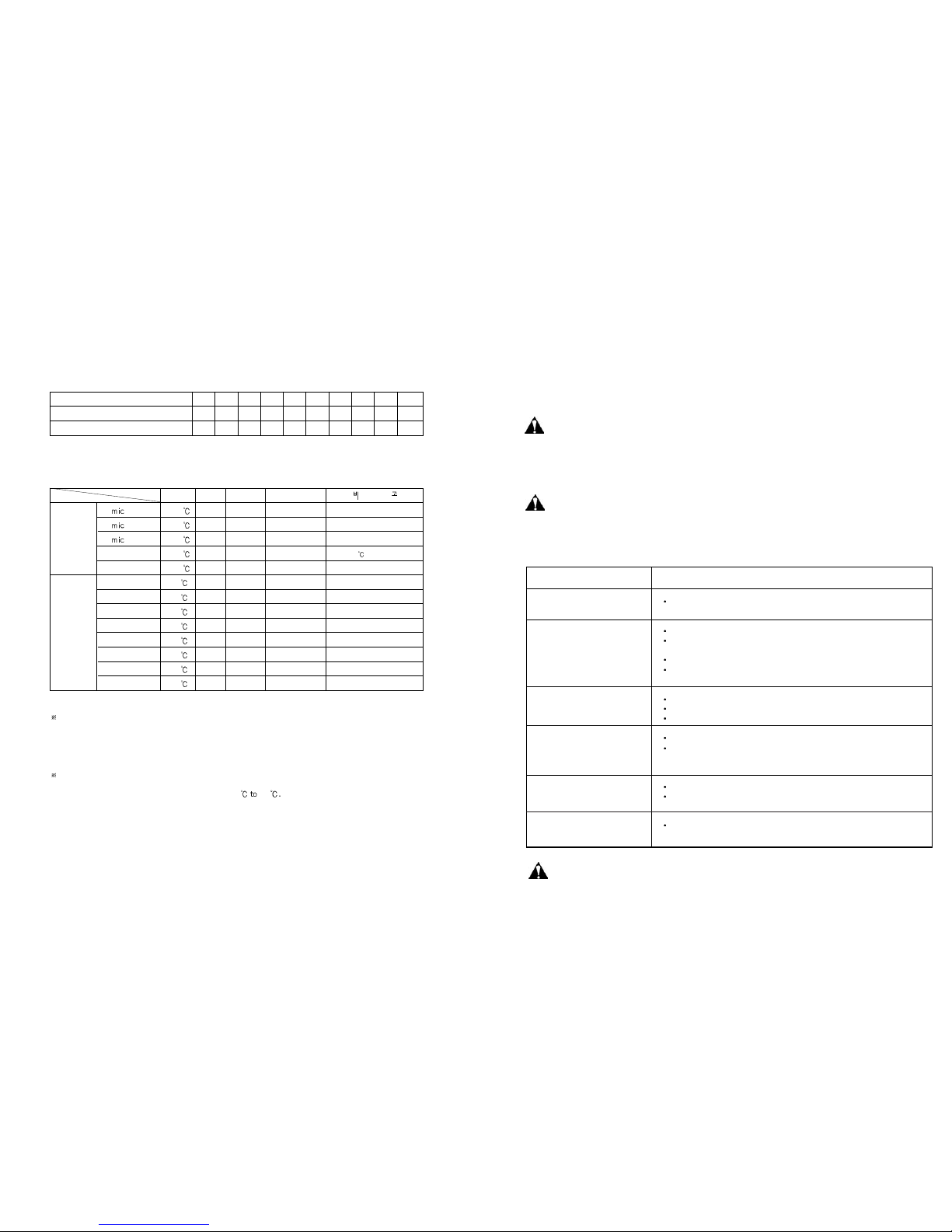
GENERAL LAMINATION GUIDE
32 (12/20)
32 (12/20)
75 (12/63)
125mic (25/100)
250mic (50/200)
COLD
3 mm
5 mm
7 mm
10 mm
15 mm
20 mm
25 mm
Mid-Prs LAMI
High-Prs LAMI
Mid-Prs LAMI
Mid-Prs LAMI
Low-Prs LAMI
Mid-Prs LAMI
3mm Mount
5mm Mount
7mm Mount
10mm Mount
15mm Mount
20mm Mount
25mm Mount
Lower by 5 after 10 min. operation
Requires Cooling Fan
Temp Speed Paper Mode
Hot
Lamination
Cold
Lamination
&
Mounting
105
100
100
100
115
40
40
40
40
40
40
40
40
6
5
4
4
3
5
5
5
5
5
5
5
5
~120mic
150mic~
-
-
-
-
-
-
-
-
-
-
-
All above is for not using Cooliong Fans
- Without cooling fans, the units can be operated for 20 minutes continuously.
But after 20 minutes the actual temperature may rise above the set temperature
(The laminated web may be some what crooked without cooling fans after long operation.)
- Continuous operation is possible with GraphicMaster laminators with Cooling Fan option.
Upon cold lamination with PRONEX UV Cold Film, silvering (appearance of white dots) may be
observed. That will disappear in about 4 hours time when left on its own. Immediate removal is
possible by performing cold lamination around 40 60
LAMINATING SPEED
MODEL
GraphicMaster-1600HR
GraphicMaster-2100HR
1 2 3 4 5 6 7 8 9 10
0.4 0.7 1.0 1.3 1.6 1.85 2.1 2.4 2.7 3.0
0.5 1.0 1.5 2.0 2.5 3.0 3.5 4.0 4.5 5.0
(m/min)
LAMINATION GUIDE

25
SPECIFICATIONS
Classifications
Power Consumption (Watts)
Dimension (W LH) mm
Max.Laminating Width (mm)
Heating System
Temperature Control
Weight (kg)
Operating Temperature ( )
Max. Laminating Speed (m/min)
Power Supply
Infrared Heater
Proportional Control by 8-bit Microprocessor (IR Sensor)
380~400V / 50~60Hz : 3 Phase
GraphicMaster-1600HR
7,500
2110 x 850 x 1395
1670
820
0~160
3
GraphicMaster-2100HR
12,000
2800 x 994 x 1540
2240
1,050
0~160
5

1
LAMINATION GUIDE
Suitable for ColorSpan, Encad, EPSON, HP prints
or other prints that doesn’t laminate with normal hot film
POP-UP DISPLAY (COLD APPLICATION)
TOP : 75 mic PRONEX UV COLD Sand, Matt,
SoftMatt, Gloss
MEDIA : Inkjet Print on 200mic
JETEL-LIGHT PROTECT media
TOP : 150 mic CHROMONEX UV Sand, Matt, Gloss
or 250 mic PERFEX Gloss, Matt
MEDIA : Off-set Prints, Inkjet or Electrostatic Prints
BOTTOM : 250 micron LIGHT PROTECT or
250 micron BLK/OPQ or
250 micron PERFEX Gloss
Suitable for making general display or with prints not
stuitable with use of cold laminating film.
POP-UP DISPLAY (HOT APPLICATION-1)
Suitable for ColorSpan, Encad, EPSON, HP prints
or other prints that doesn’t laminate with normal hot film
ROLL-UP DISPLAY (COLD APPLICATION)
TOP : 75 mic PRONEX UV COLD Sand, Softmatt,Matt
Glossy
MEDIA : Inkjet Print on 75mic JETEL-LIGHT PROTECT
media
TOP : 150 mic CHROMONEX Sand, Matt or Gloss
MEDIA : Off-set Prints, Inkjet or Electrostatic Prints
BOTTOM : 75 or 125 mic LIGHT PROTECT Film or
125 mic BKC/OPQ
Suitable for making general display or with prints not
stuitable with use of cold laminating film.
ROLL-UP DISPLAY (HOT APPLICATION)
ROLL-UP DISPLAY
Various types of displays can be created for making effective
presentation by utilizing whole range of special laminating films
made for graphics display from GMP.
Depending on the purpose and application, selection of film
material and thickness can make optimal presentation possible.
2
TOP : 150 mic CHROMONEX UV Sand, Matt, Gloss
or 250 mic PERFEX Gloss, Matt
MEDIA : Inkjet Print on 200mic
JETEL-LIGHT PROTECT media
Suitable for making general display or with prints not
stuitable with use of cold laminating film.
POP-UP DISPLAY (HOT APPLICATION-2)
TOP : 150 mic CHROMONEX UV Sand, Matt or Gloss
MEDIA : Inkjet Print on 75mic JETEL-LIGHT PROTECT media

Suitable for ColorSpan, Encad, EPSON, HP prints
or other prints that doesn’t laminate with normal hot film
OUT-DOOR DISPLAY (COLD APPLICATION)
TOP : 75 mic PRONEX UV COLD Sand,Matt,SoftMatt,Gloss
MEDIA : Inkjet Print on 175mic JETEL-BACK LIGHT media
Inkjet Print on 100mic JETEL-BACK LIGHT media
TOP : 150 mic CHROMONEX UV Sand,Matt,Gloss or
150 mic PERFEX UV Gloss
MEDIA : Off-set Prints, Inkjet or Electrostatic
BOTTOM : 250 mic LIGHT PROTECT Film or
125 mic LIGHT PROTECT Film or 250 mic BLK/OPQ or
250 mic LIGHT PROTECT Film
Suitable for making general display or with prints not
stuitable with use of cold laminating film.
OUT-DOOR DISPLAY (HOT APPLICATION)
Suitable for ColorSpan, Encad, EPSON, HP prints
or other prints that doesn’t laminate with normal hot film
INDOOR DISPLAY (COLD APPLICATION)
TOP : 75 mic PRONEX UV COLD Sand,Matt,SoftMatt
MEDIA : Off-set Prints, Inkjet or Electrostatic
BOTTOM : FOAMBOARD with Self-adhesive Layer or
Other Hard Mount Substrate
TOP & : FOAM POUCH with Photonex Hot or
BOTTOM PERFEX Gloss
MEDIA : Off-set Prints, Inkjet or Electrostatic
Suitable for making general display or with prints not
stuitable with use of cold laminating film.
INDOOR DISPLAY (HOT APPLICATION)
3 4
TOP : 150 mic CHROMONEX UV Sand, Matt, Gloss or
150 mic PERFEX UV Gloss
MEDIA : Inkjet Print on 175mic JETEL-BACK LIGHT media
Inkjet Print on 75mic JETVIN-WH/SA75(RM)

Suitable for ColorSpan, Encad, EPSON, HP prints
or other prints that doesn’t laminate with normal hot film
FLOOR GRAPHICS (COLD APPLICATION)
TOP :
200 micron PRONEX UV COLD
FLOOR MAT FILM (Orange peel Textured)
BOTTOM :
Inkjet Print on 75mic JETVIN-WH/SA75(RM) or
Inkjet Print on 75mic JETVIN-TR/SA75(RM)
STEP.1
STEP.2
In case of using EXCELJET inkjet media from GMP
TOP : 150 mic CHROMONEX UV Sand,Matt,Gloss or
75mic PRONEX UV COLD Film Sand,Matt,SoftMatt,Gloss
BOTTOM : Inkjet Print on 75mic JETEL-LIGHT PROTECT media
ROLL-UP DISPLAY
TOP : 150 mic CHROMONEX UV Sand,Matt,Gloss or
115 mic PHOTONEX UV Sand,Matt,Gloss or
75 mic PRONEX UV COLD Film Sand,Matt,SoftMatt,Gloss
BOTTOM : Inkjet Print on 175mic JETEL-BACK LIGHT media or
Inkjet Print on 75mic JETVIN-WH/SA75(RM)
OUT -DOOR DISPLAY
5 6
TOP : 150 mic CHROMONEX UV Sand,Matt,Gloss or
250 mic PERFEX Gloss, Matt or 75mic PRONEX UV
COLD Film Sand,Matt,SoftMatt,Gloss
BOTTOM : Inkjet Print on 200mic JETEL-LIGHT PROTECT media
Removable Paper Liner
POP -UP DISPLAY
TOP : 200 mic PRONEX UV COLD FLOOR MAT FILM
(Orange peel textured)
BOTTOM : Inkjet Print on 175mic JETVIN-WH/SA75(RM) or
Inkjet Print on 75mic JETVIN-TR/SA75(RM)
FLOOR GRAPHICS
TOP : 150 mic CHROMONEX UV Sand,Matt,Gloss or
115 mic PHONEX UV Sand, Matt, Gloss or
75mic PRONEX UV COLD Film Sand,Matt,SoftMatt,Gloss
32,75,125,250mic PERFEX Gloss and Matt Film
BOTTOM : Inkjet Print on 75mic,175mic JETEL-BACK LIGHT media or
Inkjet Print on 75mic,200mic JETEL-LIGHT PROTECT media
JETVIN-WH/SA75(RM) Media for Mount
IN-DOOR DISPLAY
We recommend where possible to use.
INKJET TIPS
Matts Papers
Glossy Papers
Hot process
Heat Activated Films
Cold Process
Pressure Setting Films

LEADERS IN LAMINATION TECHNOLOGY
Copyright GMP 2001. All rights reserved. Reproduction by any means of any image in this catalogue is prohibited without the prior consent of GMP and its authroized agent
Lamination Guide
for Graphic & Displays
This manual suits for next models
1
Table of contents
Other GMP Laminator manuals

GMP
GMP SURELAM-PRO540HR User manual

GMP
GMP SURELAM-PRO540HR User manual

GMP
GMP SURELAM-PRO540HR User manual

GMP
GMP EXCELMASTER-1600 User manual

GMP
GMP ELECTRO ULTRA LAMITRIM-1800 User manual

GMP
GMP PROTOPIC AUTO-540 HS User manual

GMP
GMP PROTOPIC-540 QUATRO SLIT User manual

GMP
GMP PROTOPIC AUTO-540 HS User manual

GMP
GMP QTOPIC-380 User manual

GMP
GMP EXCELAM-1100SWING User manual


