3
CE-ART 7/G+ IP G+
www.golmar.es
1. SAFETY CAUTIONS AND WARNINGS
17-09-2020 Jue
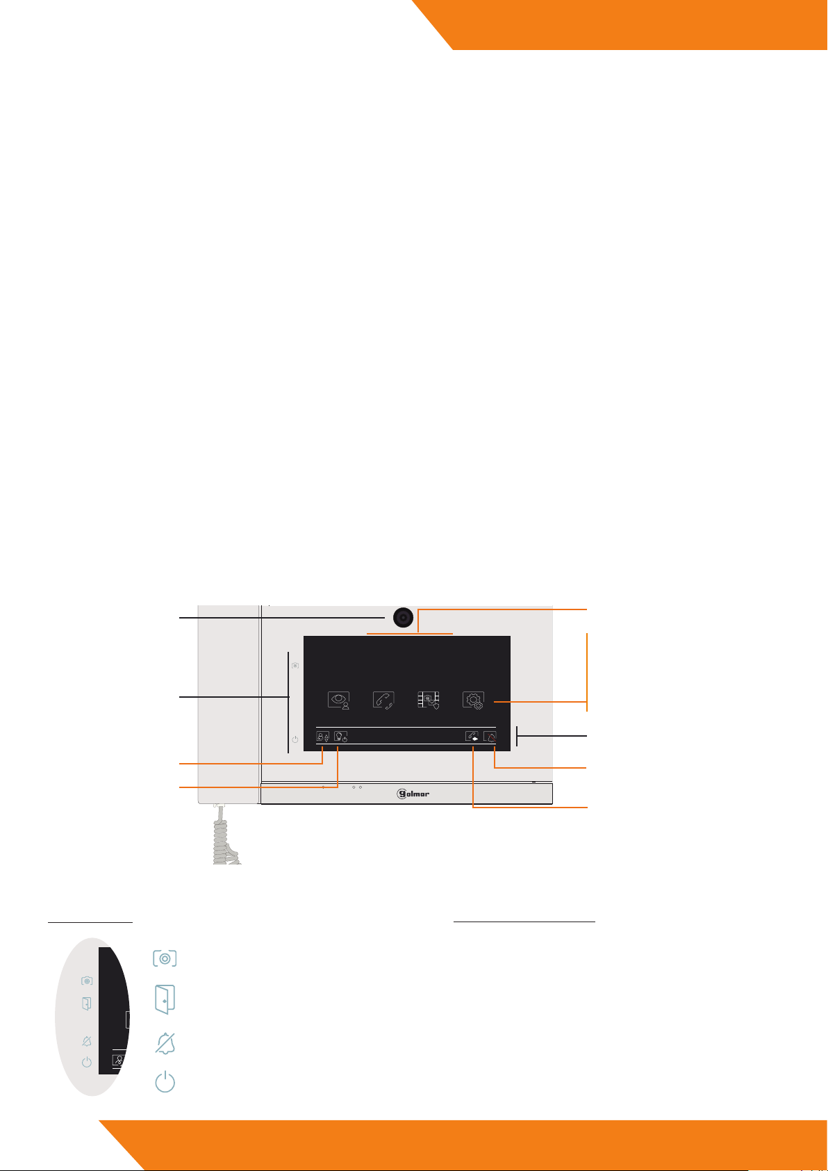
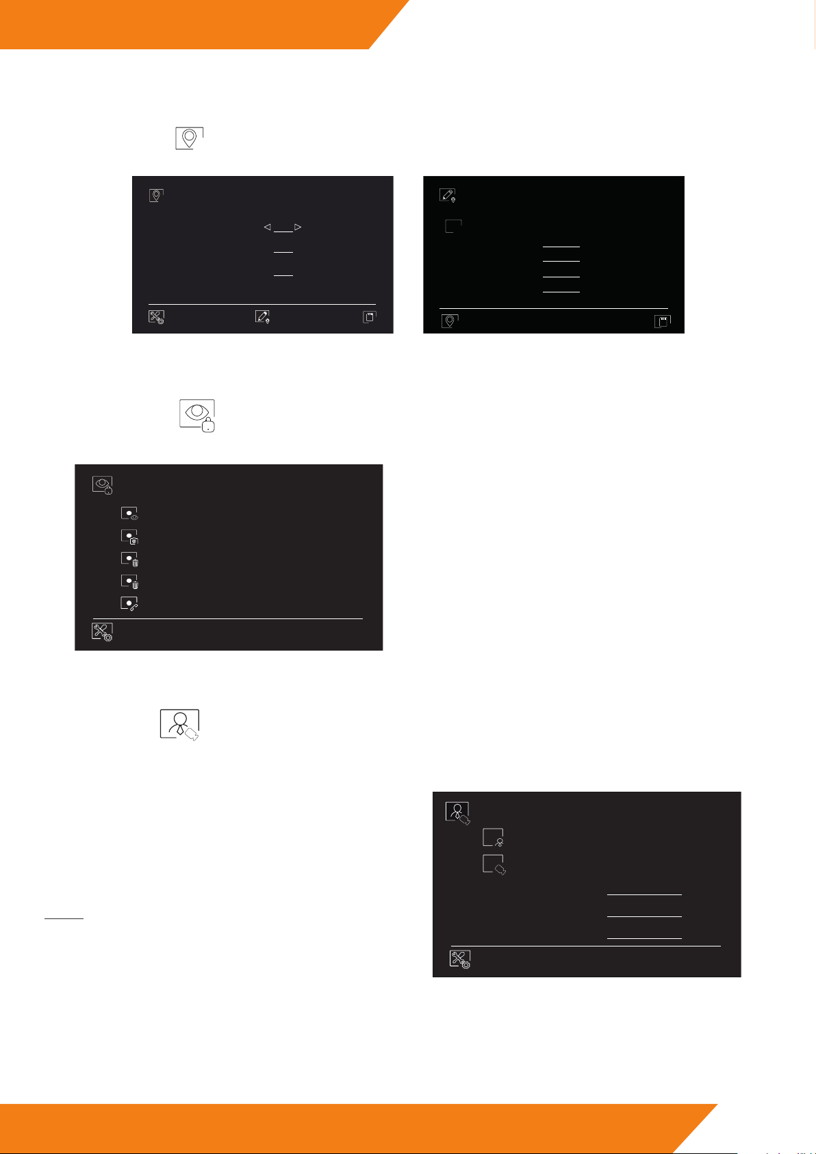
Visualizar Intercomunicación Eventos Ajustes
09:05
Status leds.
Video spy.
Enable/Disable “Do not disturb”.
Call forwarding.
Staircase light activation.
Request the li.
Time and date.
Intercom.
Event logs.
Settings.
STATUS LEDS:
Events to be reviewed.
Doctor mode activated (blinking led).
Open door activated (xed led).
Do not disturb mode activated.
Power on indicator.
Quick acces icons.
QUICK ACCESS ICONS:
Icons at the bottom row of the screen are shortcuts. To
be able to use them, the corresponding function must
be activated and in some cases must have an additional
element.
- e installation and setup of this equipment must be done by an authorized installer.
- e current regulations oblige to protect the power supply by means of a thermal magnetic circuit breaker.
- All the installation conduits must distance at least 40 cm from any other installation.
- In regards of the power supply FA-G+:
- Do not tight with excessive strength the screws of the terminal block at FA-G+ power supply.
- Install the power supply in a dry and secure area, protected against water drops.
- Avoid placing the power supply close to heating sources, humid or dusty areas.
- Do not cover the power supply ventilation openings area to assure air ow circulation.
- To prevent damages, the power supply has to be strongly mounted. Use a DIN rail 46277 (8 DIN) to x it.
- To avoid an Electrical shock, do not remove the protection cover and do not manipulate the cables connected to the power terminals.
2. SPECIFICATIONS
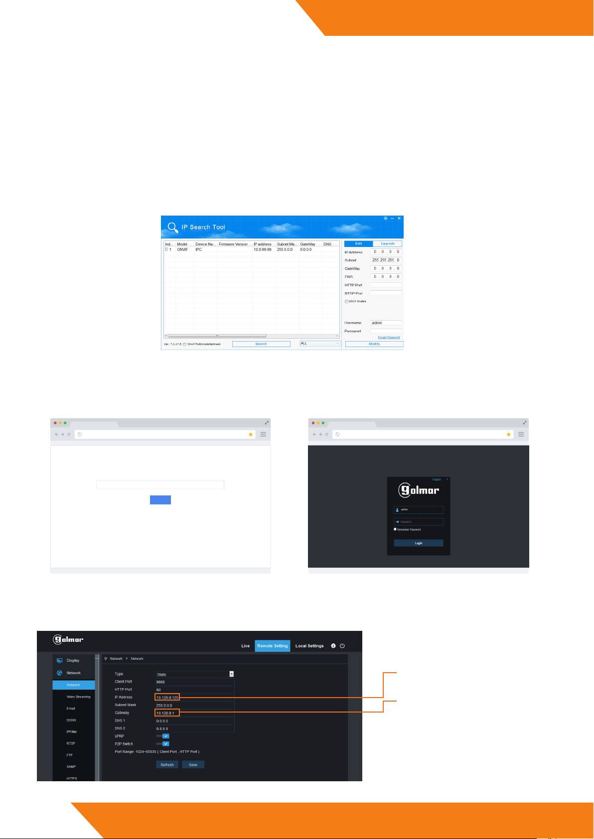
- Guard unit for TCP/IP video intercom systems with IP G+ technology..
- Installation over existing ethernet network (D4L-G+/POE are required).
- Locally powered at 12V with category 5 or higher UTP wire dor data or via PoE at 18V.
- Outpu for auxiliary sounder.
- Input for a call pushbutton.
- 7” capacitive touch screen.
- Image memory and call list.
- Call other monitors or guard units.
- High eciency speakers.
- Messaging service for short text messages and broadcast messages for emergencies.
- Video spy function of door panels and CCTV IP cameras.
- Direct door opening button.
- Connection through RJ-45 connector.
- Up to 9 guard units for each block and 19 general guard units for each installation.
3. GUARD UNIT DESCRIPTION
3.1. Front side
Built-in camera.