Good Will Instrument GDS-806 Owner's manual

-~
ARTISAN
®
~I
TECHNOLOGY
GROUP
Your definitive source
for
quality
pre-owned
equipment.
Artisan Technology
Group
Full-service,
independent
repair
center
with
experienced
engineers
and
technicians
on staff.
We
buy
your
excess,
underutilized,
and
idle
equipment
along
with
credit
for
buybacks
and
trade-ins
.
Custom
engineering
so
your
equipment
works
exactly as
you
specify.
•
Critical
and
expedited
services
•
Leasing
/
Rentals/
Demos
• In
stock/
Ready-to-ship
•
!TAR-certified
secure
asset
solutions
Expert
team
ITrust
guarantee
I
100%
satisfaction
All
tr
ademarks,
br
a
nd
names, a
nd
br
a
nd
s a
pp
earing here
in
are
th
e property of
th
e
ir
r
es
pecti
ve
ow
ner
s.
Find the Instek GDS-820C at our website: Click HERE

GDS-806/810/820/840 Programming Manual
0
Digital Storage Oscilloscope
GDS-806/810/820/840
Programming Manual
© 2004 GOOD WILL Instrument Co., Ltd. All rights reserved
GW Part No: 82DS-82000I0
Artisan Technology Group - Quality Instrumentation ... Guaranteed | (888) 88-SOURCE | www.artisantg.com

GDS-806/810/820/840 Programming Manual
1
Table of Contents Pages
1. INTRODUCTION................................................................................................................... 2
2. COMPUTER’S CONNECTION............................................................................................. 6
3. REMOTE CONTROL'S COMMANDS................................................................................ 12
4. DETAILS OF COMMAND REFERENCE ........................................................................... 19
5. STATUS REPORTS............................................................................................................ 71
6. ERROR MESSAGES.......................................................................................................... 79
7. PROGRAM TEMPLATE FOR GPIB................................................................................... 80
8. APPENDIX A: HOW CAN WE CONVERT THE HEXADECIMAL FORMAT TO A
FLOATING POINT FORMAT. ................................................................................................ 88
Due to continuous improvements in the GDS-806/810/820/840 Digital Storage
Oscilloscope, information contained in this manual is subject to change
without notice. Contact GOOD WILL, for revisions and corrections.
GOOD WILL Instrument Co., LTD.
NO. 95-11, PAO-CHUNG ROAD, HSIN-TIEN CITY,
TAIPEI HSIEN, TAIWAN
Telephone – 886-2-29179188 Fax – 886-2-2917-9189
http://www.goodwill.com.tw
Artisan Technology Group - Quality Instrumentation ... Guaranteed | (888) 88-SOURCE | www.artisantg.com

GDS-806/810/820/840 Programming Manual
2
1. Introduction
Users can drive this digital storage oscilloscope by using the GPIB (General
Purpose Interface Bus) system with a computer, or from a computer across the
RS-232 serial connection. Commands sent over either interface can read or set
any GDS-806/810/820/840’s instructions. This chapter explains how to carry out
the following tasks.
Notes for GPIB installation
If you are setting up the oscilloscope with a GPIB system, please check the
following regulations:
zOnly a maximum of 15 devices can be connected to a single GPIB bus.
zDo not use more than 20 m of cable to connect devices to a bus.
zConnect one device for every 2 m of cable used.
zEach device on the bus needs a unique device address. No two devices can
share the same device address.
zTurn on at least two-thirds of the devices on the GPIB system while you use
the system.
zDo not use loop or parallel structure for the topology of GPIB system.
Artisan Technology Group - Quality Instrumentation ... Guaranteed | (888) 88-SOURCE | www.artisantg.com

GDS-806/810/820/840 Programming Manual
3
Notes for RS-232 Configuration
This oscilloscope contains a DB 9-pin, male RS-232 connector for serial
communication with a computer or terminal. The RS-232 interface of this
oscilloscope is configured as an RS-232 “Data Terminal Equipment”, so that data
is sent from pin 3 and received on pin 2. For remote controls, the RS-232 interface
has to be connected with a computer or terminal.
Pin Assignments
The pin assignments for RS-232 interface of the oscilloscope are listed below.
1. No connection
2. Receive Data(RxD) (input)
3. Transmit Data(TxD) (output)
4. No connection
5. Signal Ground (GND)
6. No connection
7. No connection
8. No connection
9. No connection
Figure 1-1: Pin assignments for the RS232 connector
DB9 to DB9 Wiring
The wiring configuration is used for computer with DB9 connectors that configured
as Data Terminal Equipment.
Oscilloscope
(DB9, DTE)
Computer
(DB9, DTE)
Pin2
Pin3
Pin2
Pin3
Pin5Pin5
Figure 1-2: DB9 to DB9 wiring
Artisan Technology Group - Quality Instrumentation ... Guaranteed | (888) 88-SOURCE | www.artisantg.com

GDS-806/810/820/840 Programming Manual
4
When the oscilloscope is set up with a RS-232 interface, please check the
following points:
zDo not connect the output line of one DTE device to the output line of the
other.
zMany devices require a constant high signal on one or more input pins.
zEnsure that the signal ground of the equipment is connected to the
signal ground of the external device.
zEnsure that the chassis ground of the equipment is connected to the
chassis ground of the external device.
zDo not use more than 15m of cable to connect devices to a PC.
zEnsure the same configurations are used on the device as the one used
on PC terminal.
zEnsure the connector for the both side of cable and the internal
connected line are met the demand of the instrument.
Computer’s Connection for RS-232
A personal computer with a COM port is the essential facilities in order to operate
the digitizing oscilloscope via RS-232 interface.
The connections between oscilloscope and computer are as follows:
I. Connect one end of a RS-232 cable to the computer.
II. Connect the other end of the cable to the RS-232 port on the oscilloscope.
III. Turn on the oscilloscope.
IV. Turn on the computer.
Figure 1-3, shows the GPIB port and RS-232 port’s locations on the rear panel of
the oscilloscope.
Artisan Technology Group - Quality Instrumentation ... Guaranteed | (888) 88-SOURCE | www.artisantg.com

GDS-806/810/820/840 Programming Manual
5
Figure 1-3. Rear panel of the oscilloscope
(1): Main power switch
(2): AC power socket
(3): GPIB port (option for all series oscilloscopes)
(4): Fuse drawer
(5): “SELF CAL” BNC output
(6): “GO/NO GO” BNC output (option for GDS-806/810)
(7): USB connector (option for GDS-806/810)
(8): Printer port (option for GDS-806/810)
(9): RS-232 port
Artisan Technology Group - Quality Instrumentation ... Guaranteed | (888) 88-SOURCE | www.artisantg.com

GDS-806/810/820/840 Programming Manual
6
2. Computer’s Connection
A personal computer with a GPIB card is the essential stuff in order to operate the
oscilloscope via GPIB interface.
The connections between oscilloscope and computer are following:
I. Connect one end of a GPIB cable to the computer.
II. Connect the other end of the GPIB cable to the GPIB port on the Oscilloscope.
III. Turn on the oscilloscope.
IV. Turn on the computer.
The GPIB interface capabilities:
The GPIB interface of the oscilloscope corresponds to the standard of
IEEE488.1-1987, IEEE488.2-1992 and SCPI-1994. The GPIB interface functions
are listed as follows:
SH1(Source
Handshake):
The oscilloscope can transmit multilane messages
across the GPIB.
AH1(Acceptor
Handshake):
The oscilloscope can receive multilane messages
across the GPIB.
T6(Talker): Talker interface function includes basic talker, serial
poll, and unaddress if MLA capabilities, without talk
only mode function.
L4 (Listener): The oscilloscope becomes a listener when the
controller sends its listen address with the ATN
(attention) line asserted. The oscilloscope does not
have listen only capability.
Artisan Technology Group - Quality Instrumentation ... Guaranteed | (888) 88-SOURCE | www.artisantg.com

GDS-806/810/820/840 Programming Manual
7
SR1 (Service Request): The oscilloscope asserts the SRQ (Service request)
line to notify the controller when it requires service.
RL1 (Remote/Local): The oscilloscope responds to both the GTL (Go to
Local) and LLO (Local Lock Out) interface messages.
PP0 (Parallel Poll): The oscilloscope has no Parallel Poll interface
function.
DC1 (Device Clear): The oscilloscope has Device clear capability to return
the device to power on status.
DT0 (Device Trigger): The oscilloscope has no Device Trigger interface
function.
C0 (Controller) : This oscilloscope can not control other devices.
The GPIB address setting
To change the GPIB address, please use the following steps:
zPress the UTILITY button on the front panel. The utility menu provides
Interface Menu sub menu by pressing F2 softkey which GPIB sub menu is
included. Press F1 softkey to select GPIB setting menu.
For GPIB sub menu
zType GPIB: Select GPIB port.
zAddr 1~30: select the appropriate address for GPIB.
zPrevious Menu: back to previous menu.
Artisan Technology Group - Quality Instrumentation ... Guaranteed | (888) 88-SOURCE | www.artisantg.com

GDS-806/810/820/840 Programming Manual
8
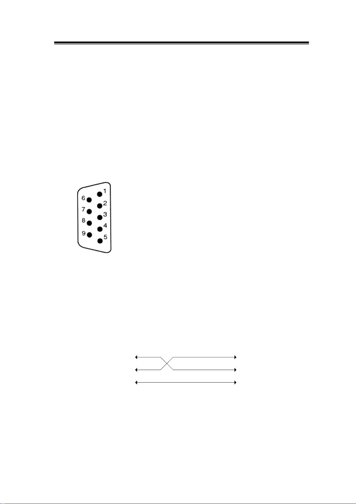
The GPIB connection testing
If you want to test the GPIB connection is whether working or not, use the National
Instrument’s “Interactive Control utility” for instance, you communicate with the
GPIB devices through calls you interactively type in at the keyboard.
The Interactive Control can help you to learn about the instrument and to
troubleshoot problems by displaying the following information on your screen after
you enter a command:
zResults of the status word (ibsta) in hexadecimal notation
zMnemonic constant of each bit set in ibsta
zMnemonic value of the error variable (iberr) if an error exists (the ERR bit is
set in ibsta)
zCount value for each read, write, or command function
zData received from your instrument
You can access online help in Interactive Control by entering help at the prompt, or
you can get help on a specific function by entering help <function> at the prompt,
where <function> is the name of the function for which you want help.
To start Interactive Control within National Instrument’s “Measurement &
Automation Explorer”, complete the following steps:
1. Select Tools→I-488.2 Utilities→Interactive Control.
2. Open either a board handle or device handle to use for further NI-488.2 calls.
Use ibdev to open a device handle, ibfind to open a board handle, or the set
488.2 command to switch to a 488.2 prompt.
Artisan Technology Group - Quality Instrumentation ... Guaranteed | (888) 88-SOURCE | www.artisantg.com

GDS-806/810/820/840 Programming Manual
9
The following example uses ibdev to open a device, assigns it to access board
gpib0, chooses a primary address of 7 with no secondary address, sets a timeout
of 10 seconds, enables the END message, and disables the EOS mode.
:ibdev
enter board index: 0
enter primary address: 7
enter secondary address: 0
enter timeout: 13
enter ‘EOI on last byte’ flag: 1
enter end-of-string mode/byte: 0
ud0:
Note: If you type a command and no parameters, Interactive Control prompts you
for the necessary arguments. If you already know the required arguments, you can
type them at the command prompt, as follows:
:ibdev 0 7 0 13 1 0
ud0:
Note: If you do not know the primary and secondary address of your GPIB
instrument, right-click on your GPIB interface in Measurement & Automation
Explorer and select Scan for Instruments. After Explorer scans your interface, it
displays your instrument address in the right window panel.
3. After you successfully complete ibdev, you have a ud prompt. The new
prompt, ud0, represents a device-level handle that you can use for further
NI-488.2 calls. To clear the device, use ibclr, as follows:
ud0: ibclr
[0100] (cmpl)
Artisan Technology Group - Quality Instrumentation ... Guaranteed | (888) 88-SOURCE | www.artisantg.com

GDS-806/810/820/840 Programming Manual
10
4. To write data to the device, use ibwrt.
ud0: ibwrt "*IDN?"
[0100] (cmpl)
count: 5
5. To read data from your device, use ibrd. The data that is read from the
instrument is displayed. For example, to read 28 bytes, enter the following:
ud0: ibrd 28
[0100] (cmpl)
count: 28
47 57 2C 20 47 44 53 2D GW, GDS-
38 32 30 2C 20 50 39 32 820, P92
30 31 33 30 2C 20 56 2E 0130, V.
31 2E 30 39 1.09
6. When you finish communicating with the device, make sure you put it offline
using the ibonl command, as follows:
ud0: ibonl 0
[0100] (cmpl)
:
The ibonl command properly closes the device handle and the ud0 prompt is no
longer available.
7. To exit Interactive control, type q.
For the details, please refer to National Instrument’s manual.
If you do not receive a proper response from the oscilloscope, please check the
power is on, the GPIB address is correct, and all cable connections are active,
Artisan Technology Group - Quality Instrumentation ... Guaranteed | (888) 88-SOURCE | www.artisantg.com

GDS-806/810/820/840 Programming Manual
11
The RS232 connection testing
If you want to test whether the RS-232 connection is working or not, you can send
a command from computer. For instance, using a terminal program send the query
command
*idn?
should return the Manufacturer, model number, serial number and firmware
version in the following format:
GW,GDS-820,P920130,V.2.01
If you do not receive a proper response from the oscilloscope, please check if the
power is on, the RS-232 configurations are the same on both sides, and all cable
connections are active.
Artisan Technology Group - Quality Instrumentation ... Guaranteed | (888) 88-SOURCE | www.artisantg.com

GDS-806/810/820/840 Programming Manual
12
3. Remote Control’s Commands
This oscilloscope can be operated from computer via the GPIB port or RS-232 port.
The remote commands of this oscilloscope are compatible with IEEE-488.2 and
SCPI standards partially.
SCPI
SCPI (Standard Commands for Programmable Instruments) is a standard that
created by an international consortium of the major test and measurement
equipment manufacturers. The IEEE-488.2 syntax has been adopted by SCPI to
furnish common commands for the identical functions of different programmable
instruments.
SCPI
IEEE-488.2 IEEE-488.2
SCPIIEEE-488.1
AABBCCDD
Interface Function
Syntax & Status Data Structure
Common Command & Queries
SCPI
Figure 3-1: the relationship between IEEE-488.1, IEEE-488.2, and SCPI.
Artisan Technology Group - Quality Instrumentation ... Guaranteed | (888) 88-SOURCE | www.artisantg.com

GDS-806/810/820/840 Programming Manual
13
As shown in the figure 3-1, the IEEE-488.1 standard locates at layer A, the layer A
is belonged to the protocol of interface function on the GPIB bus. The source
handshake (SH), acceptor handshake (AH) and talker are included in this layer (10
interface functions totally).
At layer B, the syntax and data structure could be the essence of entire
IEEE-488.2 standard. The syntax defines the function of message communication,
which contain the <PROGRAM MESSAGE> (or simply “commands”) and
<RESPONSE MESSAGE>. The two kinds of messages are represented the
syntax formation of device command and return value. The data structure is the
constitution of status reporting, which IEEE-488.2 standard have been defined.
The common commands and queries are included with layer C. Commands and
queries can be divided into two parts: mandatory and optional. Commands modify
control settings or tell the instrument to perform a specific action. Queries cause
the instrument to send data or status information back to the computer. A question
mark at the end of a command identifies it as a query.
Layer D is interrelated with device information. Different devices have different
functions. SCPI command sets are belonged to this layer.
Command Syntax
If you want to transfer any of the instructions to an instrument, and comply with
SCPI, there are three basic elements must be included.
zCommand header
zParameter (if required)
zMessage terminator or separator
Artisan Technology Group - Quality Instrumentation ... Guaranteed | (888) 88-SOURCE | www.artisantg.com

GDS-806/810/820/840 Programming Manual
14
Command Header
The command header has a hierarchical structure that can be represented by a
command tree (Figure 3-2).
:TRIGger:
:DELay :SLOP ?
:TIMe ? :TYPe
0 (Delay)1 (event)
Root node
Lower-
level
nodes
Leaf node
Figure 3-2: Tree hierarchy
The top level of the tree is the root level. A root node is located at the root level. A
root node and one or more lower-level nodes form a header path to the last node
called the leaf node.
The command header is configured by header path and leaf node. Figure 3-3
shows the command header for the leaf node.
:TRIGger:DELay:EVENt ?
Root Node
Header Path
Command Header
Leaf Node
Figure 3-3: Command header
Artisan Technology Group - Quality Instrumentation ... Guaranteed | (888) 88-SOURCE | www.artisantg.com

GDS-806/810/820/840 Programming Manual
15
Parameter
If the command has parameters, the values have to be included. In this manual,
when we expressed the syntax of the command, the < > symbols are used for
enclosing the parameter type. For instance, the syntax of the command in Figure
8-5 includes the Boolean parameter type
NOTE: Do not include the <, >, or | symbols when entering the actual value
for a parameter.
:TRIGger:DELay:MODe <Boolean>
Figure 3-4: Command Header with Parameter
Space
Parameter
Type
Table 3-1 defines the Boolean and other parameter types for the oscilloscope.
Parameter Type Description Example
Boolean Boolean numbers or values 1
0
NR1 Integers 0, 1, 18
NR2 Decimal numbers 1.5, 3.141, 8.4
NR3 Floating point numbers 4.5E-1, 8.25E+1
NRf NR1, NR2, or NR3 1, 1.5, 4.5E-1
Table 3-1: Parameter Types for Syntax Descriptions
Artisan Technology Group - Quality Instrumentation ... Guaranteed | (888) 88-SOURCE | www.artisantg.com

GDS-806/810/820/840 Programming Manual
16
For the actual value of the parameter type <Boolean>, you have to enter 0 instead
of “OFF” or enter 1 instead of “ON”.
The following example includes both the header and a value for the parameter
type:
:TRIGger:NREJ 0
Parameter values that appeared in this manual are often separated by a vertical
line. This vertical line means the same thing as the word "or," For example, values
for the parameter <Boolean> are
0|1
This is the same thing as saying "0 (off) or 1 (on)" Any single value is a valid
parameter.
Message Terminator and Message Separator
In accordance with IEEE 488.2 standard, this oscilloscope accepts any of the
following message terminators:
zLF^END Line feed code (hexadecimal 0A) with END message
zLF Line feed code
z<dab>^END Last data byte with END message
These terminators are compatible with most application programs.
A semicolon separates one command from another when the commands appear
on the same line.
Artisan Technology Group - Quality Instrumentation ... Guaranteed | (888) 88-SOURCE | www.artisantg.com

GDS-806/810/820/840 Programming Manual
17
Entering Commands
The standards that govern the command set for this oscilloscope allow for a
certain amount of flexibility when you enter commands. For instance, you can
abbreviate many commands or combine commands into one message that you
send to the oscilloscope. This flexibility, called friendly listening, saves
programming time and makes the command set easier to remember and use.
Command Characters
This oscilloscope is not sensitive to the case of command characters. You can
enter commands in either uppercase or lowercase.
You can precede any command with white space characters. You must, however,
use at least one space between the parameter and the command header.
Abbreviating Commands
Most commands have a long form and a short form. The listing for each command
in this section shows the abbreviations in upper case. For instance, you can enter
the query
:TIMebase:SCALe ?
simply as
:TIM:SCAL ?
Artisan Technology Group - Quality Instrumentation ... Guaranteed | (888) 88-SOURCE | www.artisantg.com

GDS-806/810/820/840 Programming Manual
18
Combining Commands
You can use a semicolon (;) to combine commands and queries. This oscilloscope
executes coherent commands in the order it receives them. When you coherent
queries, the oscilloscope will combine the responses into a single response
message. For example, if the frequency and amplitude of the signal are equal to
100kHz and 1V, the command
:MEASure:FREQuency?;:MEASure:VAMPlitude?
returns the message
100kHz 1v
Artisan Technology Group - Quality Instrumentation ... Guaranteed | (888) 88-SOURCE | www.artisantg.com
This manual suits for next models
3
Table of contents
Other Good Will Instrument Test Equipment manuals

Good Will Instrument
Good Will Instrument GOS-6051 User manual

Good Will Instrument
Good Will Instrument Instek GRS-6052 User manual

Good Will Instrument
Good Will Instrument instek GOS-6200 User manual

Good Will Instrument
Good Will Instrument GSB-01 User manual

Good Will Instrument
Good Will Instrument GDS-3000A Series User manual

Good Will Instrument
Good Will Instrument GOS-310 User manual

Good Will Instrument
Good Will Instrument instek GOS-6200 User manual

Good Will Instrument
Good Will Instrument PEL-2000B Series User manual