GOS-6051/6050/6031/6030 OSCILLOSCOPE
USER MANUAL
⎯4 ⎯
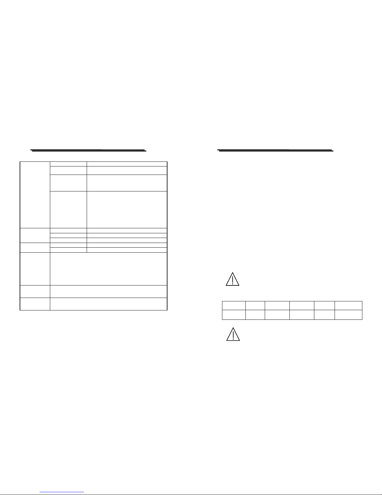
2.TECHNICAL SPECIFICATIONS
Type
6-inch rectangular type with internal graticule;
0%, 10%, 90% and 100% markers.
8 x10 DIV (1 DIV = 1 cm)
Accelerating Potential Approx. 10kV (GOS-6051/6050),
2kV (GOS-6031/6030)
INTEN and FOCUS Front panel control.
Illumination Provided (GOS-6051/6031)
Trace Rotation Provided.
CRT
Z-axis Input Sensitivity: at least 5V
Polarity : positive going input decrease intensity
Usable frequency range: DC to 2MHz.
Max. input voltage: 30V (DC +AC peak) at 1kHz
or less.
Input Impedance: approx. 33kΩ(GOS-6051/6050)
47kΩ(GOS-6031/6030)
Sensitivity Accuracy 1mV~2mV/DIV ±5%, 5mV~20V/DIV ±3%, 14
calibrated steps in 1-2-5 sequence.
Vernier Vertical
Sensitivity
Continuously variable to 1/2.5 or less of panel
indicate value.
GOS-6051/6050 Bandwidth(-3dB) Rise Time
5mV~20V/DIV DC~50MHz Approx. 7ns
1mV~2mV/DIV DC~7MHz Approx. 50ns
GOS-6031/6030 Bandwidth(-3dB) Rise Time
5mV~20V/DIV DC~30MHz Approx. 11.7ns
Bandwidth(-3dB) and
Rise Time
1mV~2mV/DIV DC~7MHz Approx. 50ns
Maximum Input Voltage 400V (DC + AC peak) at 1kHz or less.
Input Coupling AC, DC, GND
Input Impedance Approx. 1MΩ±2% // approx. 25pF
Vertical Modes CH1, CH2, DUAL(CHOP/ALT), ADD, CH2 INV.
CHOP Frequency Approx. 250kHz.
VERTICAL
SYSTEM
Dynamic Range GOS-6051/6050: 6DIV at 50MHz,
GOS-6031/6030: 8DIV at 20MHz, 6DIV at 30MHz
GOS-6051/6050/6031/6030 OSCILLOSCOPE
USER MANUAL
⎯5 ⎯
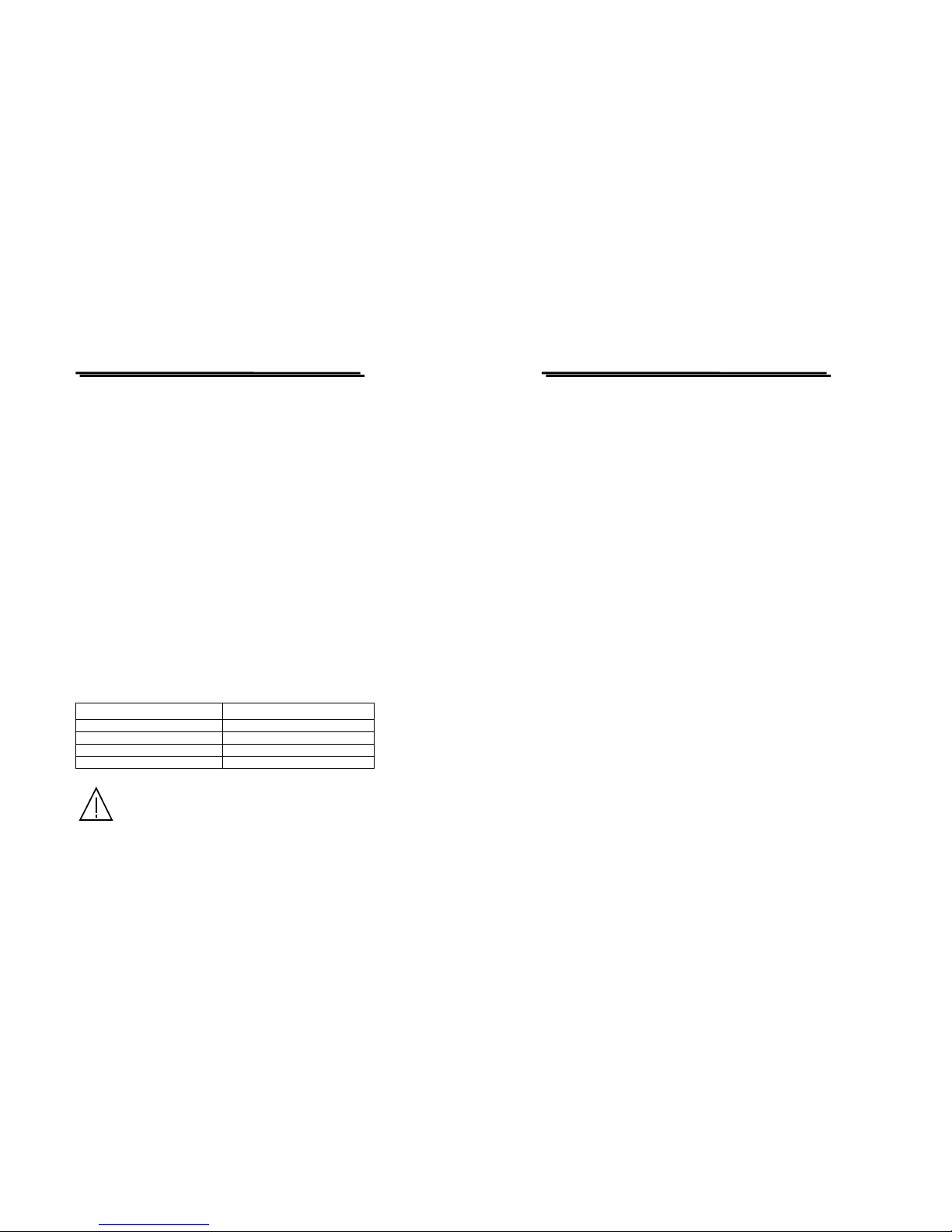
Sweep Time
0.2μs/DIV~0.5s/div, 20 steps selectable in 1-2-5
sequence, continuous variable control between steps
at least 1:2.5.
Accuracy ±3%, ±5% at ×5 and ×10 MAG, ±8% at ×20 MAG
Sweep Magnification ×5, ×10, ×20 MAG
Maximum Sweep Time
(at MAG)
GOS-6051/6050:20ns/DIV(10ns/DIV uncalibrated)
GOS-6031/6030:50ns/DIV(10ns/DIV~40ns/DIV
uncalibrated.
HORIZONTAL
SYSTEM
ALT-MAG Function Available.
Trigger Modes AUTO, NORM, TV
Trigger Source VERT-MODE, CH1, CH2, LINE, EXT.
Trigger Coupling AC, HFR, LFR, TV-V(-), TV-H(-).
Trigger Slope “+” or “- ” polarity.
GOS-6051/
GOS-6050
CH1,
CH2
VERT-
MODE EXT
20Hz~5MHz 0.5 DIV 2.0 DIV 200mV
5MHz~40MHz 1.5 DIV 3.0 DIV 800mV
40MHz~50MHz 2.0 DIV 3.5 DIV 1V
GOS-6031/
GOS-6030
CH1,
CH2
VERT-
MODE EXT
20Hz~2MHz 0.5 DIV 2.0 DIV 200mV
2MHz~20MHz 1.5 DIV 3.0 DIV 800mV
20MHz~30MHz 2.0 DIV 3.5 DIV 1V
Trigger Sensitivity
TV sync pulse more than 1 DIV (CH1, CH2, VERT-
MODE) or 200mV (EXT).
External Trigger Input
Input impedance: Approx. 1MΩ//25pF(AC
coupling)
Max. input voltage: 400V (DC + AC peak) at 1kHz.
TRIGGER
SYSTEM
Hold-off Time Variable.
Input X-axis : CH1, Y-axis : CH2
Sensitivity 1mV/DIV~20V/DIV.
Bandwidth X-axis: DC~500kHz (-3dB)
X-Y
OPERATION Phase Difference 3°or less from DC to 50kHz
CH1 Signal Output
Voltage : approx. 20mV/DIV (with 50Ω
terminal.)
Bandwidth: 50Hz to at least 5MHz.
OUTPUT
SIGNAL
Calibrator output Voltage : 0.5V±3%,
Frequency: approx. 1kHz, square wave.