PRODUCT DESIGN
4
GSX13modelsareavailablein11/2through5tonsizesand
use R-410A refrigerant. They are designed for 208/230 volt
singlephaseapplications.
The condenser air is pulled through the condenser coil by a
direct drive propeller fan. This condenser air is then dis-
charged out of the top of the cabinet.
These units are designed for free air discharge, so no addi-
tional resistance like duct work shall be attached.
The suction and liquid line connections on present models
areofthesweattypeforfieldpipingwithrefrigeranttypecop-
per. Front seating valves are factory installed to accept the
fieldruncopper. The total refrigerantcharge for a normal in-
stallationisfactoryinstalledinthe condensingunit.GSXunits
are charged for the matching evaporator coil and a 15 foot
refrigerantlineset.
Systems should be properly sized by heat gain and loss
calculations made according to methods of the Air Condi-
tioning Contractors Association (ACCA) or equivalent. It is
the contractors responsibility to ensure the system has ad-
equate capacity to heat or cool the conditioned space.
GSXmodels usetheCopeland Scroll"Ultratech"Seriescom-
pressorswhichare specifically designed for R-410A refriger-
ant. Thereareanumber of design characteristics whichare
differentfromthe traditional reciprocating and/or scroll com-
pressors.
"Ultratech" Series scroll compressors will not have a dis-
chargethermostat, some of the earlymodel scroll compres-
sorsrequireddischarge thermostats.
Due to their design Scroll compressors are inherently more
tolerantofsmall quantities of liquid refrigerant.
NOTE: Eventhough thecompressorsectionofa Scroll com-
pressor is more tolerant of liquid refrigerant, continued
floodback or flooded start conditions may wash oil from the
bearingsurfacescausing premature bearing failure.
"Ultratech" Series scroll compressors use "POE" or
polyolesteroil whichisNOT compatiblewithmineraloilbased
lubricants like 3GS. "POE" oil must be used if additional oil
isrequired.
Operating pressures and amp draws may differ from stan-
dardreciprocatingand/orscroll compressors. This informa-
tion may be found in the "Cooling Performance Data" sec-
tion.
IMPORTANT NOTE: Because of the potential damage to
compressors,donot allow suction pressureatservice valve
to drop below 20 PSIG when pumping unit system down for
repair. Outdoor section, depending on line set length and
amount of charge in system, may not be able to hold the
entiresystemcharge.
WARNING
To avoid possible injury, explosion or death, practice
safe handling of refrigerants.
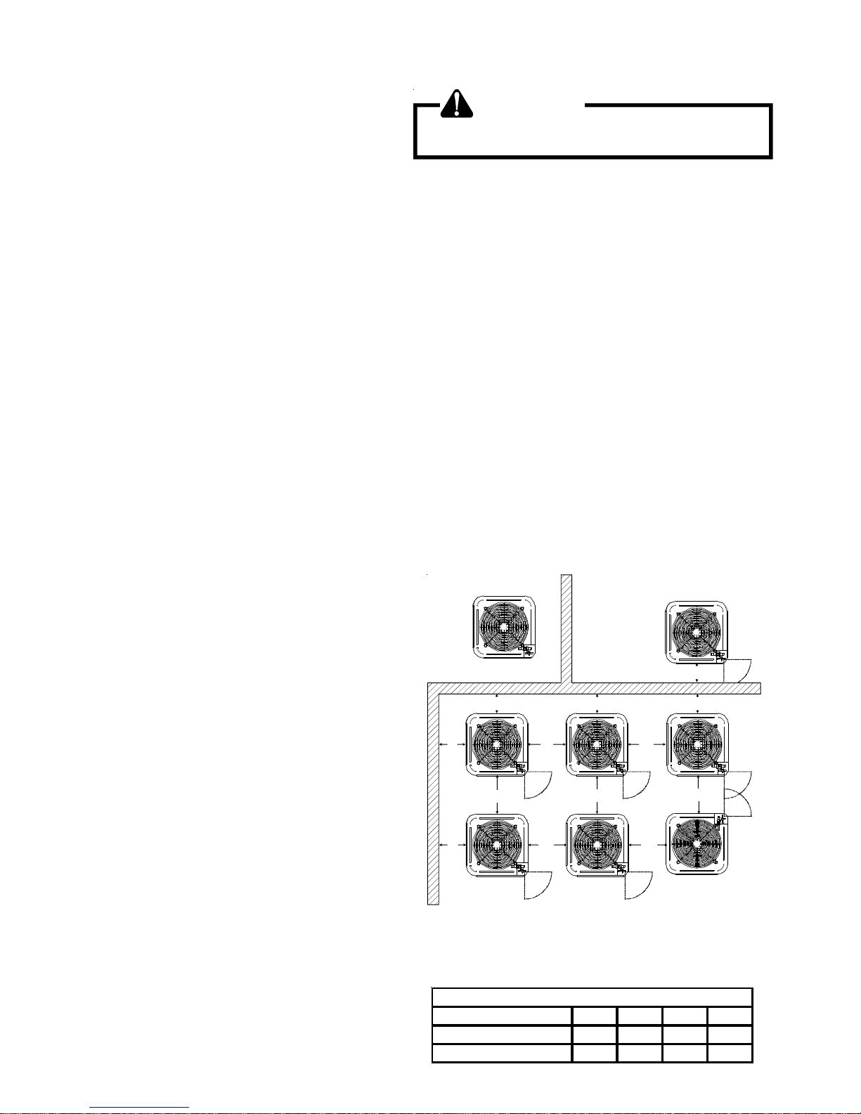
Special consideration must be given to location of the con-
densing unit(s) in regard to structures, obstructions, other
units, and any/all other factors that may interfere with air
circulation. Where possible, the top of the unit should be
completely unobstructed; however, if vertical conditions re-
quire placement beneath an obstruction there should be a
minimum of 60 inches between the top of the unit and
theobstruction(s). The specified dimensionsmeetrequire-
mentsforair circulation only. Consultallappropriate regula-
torycodes prior to determiningfinal clearances.
Another important consideration in selecting a location for
the unit(s) is the angle to obstructions. Either side adjacent
the valves can be placed toward the structure provided the
sideawayfromthestructuremaintainsminimumserviceclear-
ance. Cornerinstallations are strongly discouraged.
DO NOT locate the unit:
– Directlyundera vent termination fora gas appliance.
Model Type
BCA
Residential 10" 10" 18" 20"
Light Commercial 12" 12" 18" 24"
Minimum Airflow Clearance
– Within 3 feet of a clothes dryer vent.
– Where the refreezing of defrost water would create a
hazard.
– Where water may rise into the unit.
OK!
OK!
AA AAA
A
CC
CCOK!
OK!
OK!
OK!
NOT
RECOMMENDED
AA
AA AA
AA
AA
B B B
B