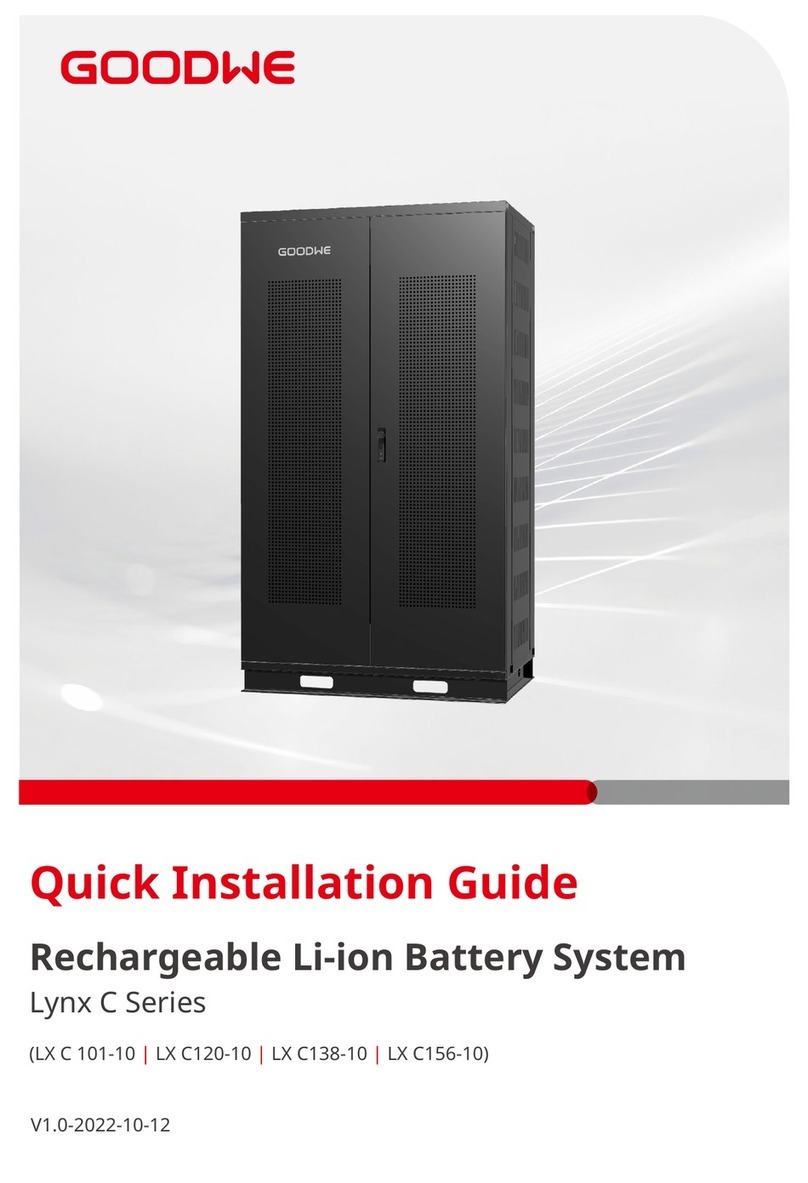
Goodwe Lynx C Series User manual

Rechargeable Li-ion Battery System
Lynx C Series
V 1.0 2022-10-15
User Manual

I
Copyright Statement
User Manual V1.0-2022-10-15
The information in this user manual is subject to change due to product updates or other rea-
sons. This guide cannot replace the product labels or the safety precautions in the user manual
unless otherwise specied. All descriptions in the manual are for guidance only.
and other GOODWE trademarks are trademarks of GoodWe Technologies
Co.,Ltd. All other trademarks or registered trademarks mentioned in this manual are owned by
GoodWe Technologies Co.,Ltd.
Trademarks
NOTICE
No part of this manual can be reproduced or transmitted to the public platform in any form or
by any means without the prior written authorization of GoodWe Technologies Co., Ltd.
Copyright ©GoodWe Technologies Co., Ltd., 2022. All rights reserved

II
CONTENT User Manual V1.0-2022-10-15
Content
01 About This Manual .................................................................IV
1.1 Applicable Model ................................................................................................IV
1.2 Target Audience ..................................................................................................IV
1.3 Symbol Denition ...............................................................................................IV
1.4 Updates ...............................................................................................................IV
02 Safety Precaution ................................................................. 01
2.1 General Safety ....................................................................................................01
2.2 Installation Precaution ......................................................................................01
2.3 Maintenance Precaution ..................................................................................03
2.4 Battery Safety ....................................................................................................03
2.5 Emergency Measures ........................................................................................03
2.6 EU Declaration of Conformity ...........................................................................03
03 Product Introduction ............................................................ 04
3.1 Product Overview ..............................................................................................04
3.2 Battery Cabinet .................................................................................................05
3.3 PCU .....................................................................................................................06
3.4 Indicator ............................................................................................................07
3.5 Battery Module .................................................................................................07
3.6 Nameplate .........................................................................................................08
04 Storage and Package ............................................................ 09
4.1 Storage Environment ........................................................................................ 09
4.2 Packing List ........................................................................................................09
05 System Installation ............................................................... 11
5.1 Installation Environment ..................................................................................11
5.2 Space Requirements .........................................................................................11
5.3 Angle Requirements ..........................................................................................12
5.4 Moving the BS ....................................................................................................12
5.5 Installing the BS .................................................................................................12
06 Electrical Connection ........................................................... 15
6.1 Connecting PE Cable .........................................................................................15
6.2 Connecting Battery Communication Cable ....................................................16
6.3 Connecting Inverter Communication Cable ....................................................17
6.4 Connecting Power Connecting Bar ..................................................................17
6.5 Connecting Inverter Power Cable ....................................................................18
6.6 (Optional) Connecting Single Phase AC Power Cable ....................................19

III
CONTENT
User Manual V1.0-2022-10-15
07 System Operation ................................................................. 20
7.1 Check before Power ON ....................................................................................20
7.2 Power ON ...........................................................................................................20
7.3 Indicator ............................................................................................................. 21
7.4 Parameter Setting ..............................................................................................21
7.5 Power OFF .........................................................................................................22
08 Maintenance ........................................................................ 23
09 Parameters .......................................................................... 24

IV
01 About This Manual User Manual V1.0-2022-10-15
01 About This Manual
1.1 Applicable Model
1.2 Target Audience
This manual describes the product information, installation, electrical connection, commissioning,
troubleshooting and maintenance of Lynx C Series Rechargeable Li-ion Battery System for
Commercials and Industries (hereinafter referred to as the Lynx C BS in short). Read through this
manual before installing and operating the product. All the installers and users have to be familiar
with the product features, functions, and safety precautions. This manual is subject to update
without notice. For more product details and latest documents, visit https://en.goodwe.com.
This manual applies to trained and knowledgeable technical professionals. The technical
personnel has to be familiar with the product, local standards, and electric systems.
This manual applies to the listed Lynx C BS below:
Model Usable Energy (kWh)
LX C101-10 101.38
LX C120-10 119.81
LX C138-10 138.24
LX C156-10 156.67
Dierent levels of warning messages in this manual are dened as follows:
DANGER
Indicates a high-level hazard that, if not avoided, will result in death or serious injury.
Indicates a medium-level hazard that, if not avoided, could result in death or serious injury.
CAUTION
Indicates a low-level hazard that, if not avoided, could result in minor or moderate injury.
NOTICE
Highlight and supplement the texts. Or some skills and methods to solve product-related
problems to save time.
1.4 Updates
The latest document contains all the updates made in earlier issues.
V1.0 2022-10-15
First Issue
1.3 Symbol Denition

02 Safety PrecautionUser Manual V1.0-2022-10-15
01
02 Safety Precaution
NOTICE
The Lynx C BS are designed and tested strictly in compliance with related safety rules. Read and
follow all the safety instructions and cautions before any operations. Improper operation might
cause personal injury or property damage as the products are electrical equipment.
2.1 General Safety
NOTICE
• The information in this user manual is subject to change due to product updates or other
reasons. This guide cannot replace the product labels or the safety precautions in the user
manual unless otherwise specied. All descriptions here are for guidance only.
• Read through this document before installation to learn about the product and the
precautions.
• All operations should be performed by trained and knowledgeable technicians who are
familiar with local standards and safety regulations.
• Use insulating tools and wear personal protective equipment (PPE) when operating the
Lynx C BS products to ensure personal safety.
• Strictly follow the installation, operation, and conguration instructions in this manual. The
manufacturer shall not be liable for equipment damage or personal injury if you do not
follow the instructions. For more warranty details, visit:https://en.goodwe.com/warranty.
2.2 Installation Precaution
WARNING
• Please keep Power O before any operations to avoid danger. Strictly follow all safety
precautions outlined in this manual and safety labels on the equipment.
• The Lynx C BS is a high voltage system. Do not touch or operate it. Keep away from it. Only
professionals are allowed!
• Please use appropriate tools and take protective measures when installing and maintaining
heavy equipment. Improper operations will cause personal injuries.
• Do not use the battery module or Power Control Unit (hereinafter referred to as PCU in
short) if it is defective, broken, or damaged.
• Do not disassemble, modify, or replace any part of the battery module or PCU without
ocial authorization from the manufacturer.
• Pay attention to the negative and positive during installation to avoid reverse polarity
connection. Otherwise the short circuit may cause personal injuries and damage to the
equipment.

User Manual V1.0-2022-10-15
02
02 Safety Precaution
Symbol Description Symbol Description
Potential risks exist. Wear proper
personnel protectives before any
operations.
Install the equipment away from
re sources.
HIGH VOLTAGE HAZARD. High
voltage exists during the
equipment's running.
Ensure the equipment is power o
before any operations.
Keep the equipment away from
children.
Operate the equipment properly to
avoid explosion. No extinguishing with water.
The equipment contains corrosive
electrolytes. In case of a leak in
the equipment, avoid contact the
leaked liquid or gas.
Do not dispose of the equipment
with household garbage at its end
of life. Dispose it according to local
laws and regulations. Or send it to
the manufacturer.
Batteries contain ammable
materials. Beware of re.
Put the battery in the right place
and recycle it in compliance with
local environmental regulations.
Read through the user manual
before any operations.
Pay attention to safety protection
during installation, operation and
maintenance.
No stepping. Grounding. To indicate PE cable
connection position.
CE Marking. TUV Marking.
RCM Marking. --
Symbol Description
DANGER
• All labels and warning marks should be visible after the installation. Do not scrawl,
damage, or cover any label on the device.
• Warning labels on the BS are as follows.

02 Safety PrecautionUser Manual V1.0-2022-10-15
03
The Lynx C BS sold in the European market meets the following directives and requirements:
• Electromagnetic compatibility Directive 2014/30/EU (EMC)
• Electrical Apparatus Low Voltage Directive 2014/35/EU (LVD)
• Restrictions of Hazardous Substances Directive 2011/65/EU and (EU) 2015/863 (RoHS)
• Waste Electrical and Electronic Equipment 2012/19/EU
• Registration, Evaluation, Authorization and Restriction of Chemicals (EC) No 1907/2006
(REACH)
You can download the EU Declaration of Conformity on the ocial website: https://en.goodwe.
com.
WARNING
Damaged battery modules may leak electrolyte. Do not contact the electrolyte or volatile gas
once there is leakage. Please ask After-sales Service for help immediately.
Anyone contact the leakage accidentally has to do as the following:
• Inhalation:
Evacuate from the contaminated area, and seek immediate medical assistance.
• Eye contact:
Rinse your eyes for at least 15 minutes with clean water and seek immediate medical
assistance.
• Skin contact:
Thoroughly wash the touch area with soap and clean water, and seek immediate medical
assistance.
• Ingestion:
Induce vomiting, and seek immediate medical assistance.
2.5 Emergency Measures
2.4 Battery Safety
WARNING
• Do not charge the battery at lower temperature. Otherwise it may decrease the capacity of
the BS.
• Do not dis-/charge the battery exceeding the nominal dis-/charge current.
• It is strictly forbidden to reverse the polarity connection. Otherwise the strong current or
high temperature generated from the battery may cause personal injury or re risk.
2.3 Maintenance Precaution
WARNING
• Do not pull or plug the terminals and connecting cables during the running of the BS.
Otherwise it may cause dangers to the safety.
• Contact After-sales Service if the battery module shall be replaced or added.
• Power o the BS the moment there is abnormality happening during the running. Contact
the related personnel as soon as possible.
• Do not hit, pull, drag, or step on the equipment, or stab into the cover of the equipment
with sharp objects, or put unrelated items into any part of the battery cabinet.
2.6 EU Declaration of Conformity

03 Product Introduction User Manual V1.0-2022-10-15
04
• This manual is mainly about product introduction, application scenarios, installation,
commissioning, maintaining and technical parameters of the Lynx C BS.
• The Lynx C BS is mainly composed of Lynx C series battery modules, PCU and battery cabinet.
• Below are the inverters applicable in the Lynx C BS:
03 Product Introduction
3.1 Product Overview
BS Model PCU Quantity Battery Cabinet Quantity Battery Module Quantity
LX C101-10 1 1 11
LX C120-10 1 1 13
LX C138-10 1 1 15
LX C156-10 1 1 17
Below are the congurations about dierent BS:
GoodWe Inverter

User Manual V1.0-2022-10-15 03 Product Introduction
05
3.2 Battery Cabinet
Length Width
Height
Front View Right View Left View
Model Length (mm) Width (mm) Height (mm)
LX C101-10 1155 730 1650
LX C120-10
LX C138-10 1155 730 2065
LX C156-10
Handle
BS Routing Hole
Slot

03 Product Introduction User Manual V1.0-2022-10-15
06
3.3 PCU
No. Silk Print Parts Description
1 B+ Battery positive
terminal
To connect with the positive polarity of the battery
module.
2 QF3 DC circuit breaker Used when the BS is self-powered.
3 QF2 AC circuit breaker Used when the BS requires external power supply.
4 QF1 Main circuit
breaker The main circuit breaker for the BS.
5 HRL Indicator To display the working status of BS.
6 B- Battery negative
terminal
To connect with the negative polarity of the battery
module.
7P-
Power input/
output port
(Negative)
To connect the inverter negative power port.
8BMS POW AC power supply
port To connect the inverter AC output port.
9P+
Power input/
output port
(Positive)
To connect the inverter positive power port.
10 COM External COM
port To connect the inverter for communication.
11 BMU
COM Internal COM port To connect the battery module for communication.

User Manual V1.0-2022-10-15 03 Product Introduction
07
3.5 Battery Module
No. Parts Description
1Connector for battery
communication
To connect PCU or other battery modules for
communication.
2Battery positive polarity -
3Battery negative polarity -
4 Battery hoisting hole To hoist the battery modules into the cabinet.
5Battery xing hole To x the battery modules within the cabinet.
525mm
677mm
202mm
3.4 Indicator
No. Red Green Description
1
-
ON The BS is in operation.
2SINGLE FLASH The BS is in idle status.
3DOUBLE FLASHES The BS is on standby.
4SINGLE FLASH
-
Slight alarm
5DOUBLE FLASHES Medium alarm
6 ON A fault has occurred.

03 Product Introduction User Manual V1.0-2022-10-15
08
3.6 Nameplate
GOODWE trademark, product type, and
product model
Technical parameters
Safety symbols and certication marks
Contact information and serial number
The nameplate is for reference only.

User Manual V1.0-2022-10-15 04 Storage and Package
09
04 Storage and Package
4.1 Storage Environment
If the equipment is not to be installed or used immediately, please ensure that the storage
environment meets the following requirements:
• Pack the equipment into a packing box and put some desiccant in the box before sealing.
• Put the equipment back in the packing box if it is not to be installed in 3 days after unpacking.
• If the battery modules are going to be kept for more than 30 days, adjust SOC to 40%-60%
and dis-/charge them once every 3 months.
• Recommended storage temperature:
-20℃~45℃ (less than one month) or 0℃~35℃ (less than a year).
• Recommended storage humidity: 0%~95%RH (no condensation). Do not install the battery if
there is moisture or condensation.
• Place the equipment in a cool place, far away from the direct sunlight.
• Keep the equipment away from ammable, explosive, and corrosive matters.
• Keep the equipment away from the rain.
• Protect the BS from damage during transportation and storage.
• It is strictly forbidden to put the batteries into re. Otherwise it might be exploded.
• It might cause a re to the BS when the ambient temperature exceeds 150℃.
4.2 Packing List
• The packing of the BS is mainly composed of the packages of the battery modules and the
battery cabinet.
• Check whether the packing is damaged and conrm the BS model before unpacking. Do not
unpack the product if you nd any damage or the model is not what you requested. Contact
After-sales Service as soon as possible.
• Check whether the deliverables are intact and complete rst after unpacking. Contact the
After-sales Service as soon as possible for anything wrong.
Battery Module
Battery Module x N
No. Model Battery Module Quantity (Pieces)
1 LX C101-10 11
2 LX C120-10 13
3 LX C138-10 15
4 LX C156-10 17

04 Storage and Package User Manual V1.0-2022-10-15
10
• All the other accessories except the battery cabinet are put in the battery cabinet.
• The quantity of AC connectors depends on the specic BS conguration.
Accessories LX C101-10 LX C120-10 LX C138-10 LX C156-10
Battery power connecting bar
(pieces) 9 11 13 15
Battery COM cable (pieces) 10 12 14 16
M6 screw (pieces) 56 56 72 72
M8 screw (pieces) 24 28 32 36
Sealing plate (pieces) 2 0 2 0
Battery Cabinet and Accessories
Battery cabinet x 1*1 AC connector x 1 COM connector x 1
Power output
connector x 1
Battery power
connecting bar A x 1
Battery power
connecting bar B x 1
Battery power
connecting bar C x 1
Battery power
connecting bar D x 1
COM cable between
PCU and battery x 1
COM cable between
batteries x N M6 screw x N M8 screw x N
Mounting hook x 4 Sealing plate x N
NA NA

User Manual V1.0-2022-10-15 05 System Installation
11
5.1 Installation Environment
• Install the BS on a at ground with sucient bearing capacity. Increase the bearing capacity
and atness of the ground by laying the foundation, adding bearing plates, and so on.
• The BS shall be installed indoor.
• The optimal working temperature for the BS is 20~40℃.
• The working temperature for the BS shall not exceed 50℃.
• Install the equipment away from heat/cold source.
• Do not install the equipment in a place where the temperature changes extremely.
• Install the equipment away from strong interferences.
• Keep children away from the equipment.
• Do not install the equipment in places prone to accumulate water.
• Do not put ammable or explosive matters near the equipment.
• In the event of a re, please make sure that the carbon dioxide extinguisher or Novac1230
or FM-200 is nearby. The re cannot be put out by water or ABC dry powder extinguisher.
Fireghters are required to wear full protective clothing and self-contained breathing
apparatus.
5.2 Space Requirements
05 System Installation
≥300mm
≥600mm ≥600mm
≥600mm

05 System Installation User Manual V1.0-2022-10-15
12
CAUTION
Move the BS to the site before installation. Follow the instructions below to avoid personal
injury or equipment damage.
1. Consider the weight of the equipment before moving it. Assign enough personnel to move
the equipment to avoid personal injury.
2. Keep the equipment in balance to avoid its falling down during moving.
5.4 Moving the BS
5.3 Angle Requirements
5.5 Installing the BS
NOTICE
• Ensure that the ground is at.
• Ensure that the battery cabinet is vertically standing on the ground without risk of
inclination.

User Manual V1.0-2022-10-15 05 System Installation
13
Step 1 Use the fork lift to move the battery cabinet to the installing place.
Step 2 Open the battery cabinet and take out the accessory package.
Step 3 Use the hook to move the battery module to the fork lift or elevating devices.
Step 4 Use the fork lift or the elevating devices to install each battery module into the battery
cabinet from bottom to top. For LX C101-10 and LX C138-10, do not install any battery module
on the top layer.
Step 5 Use M6 screws to x the battery module and the sealing plate (the sealing plate is only
used on the top layer for LX C101-10 and LX C138-10).
1
2
1
1
2
3

05 System Installation User Manual V1.0-2022-10-15
14
3
12
30-100mm
4
4
5
M6
4.5-6N·m
15
1
2
3
4
5
6
7
8
9
10
11
12
13
14
16
1
2
10
3
11
4
12
5
13
6
14
7
15
8
9
17

User Manual V1.0-2022-10-15 06 Electrical Connection
15
NOTICE
• Connect the PE cable rst before electrical connection. Disconnect the PE cable at last
during dismantling the equipment.
• The PE cable should be prepared by customers.The cross-sectional area of the PE cable
conductor: 8mm2.
LL
06 Electrical Connection
WARNING
• Ensure all switches of PCU and its upstream switches are disconnected before any electrical
connections.
• Place the cables at least 30mm away from the heating components or heat sources, otherwise
the insulation layer of the cables may be aging or broken due to high temperature.
• Tie the cables of the same type together, and place cables of dierent types at least 30mm
apart. Do not place the cables entangled or crossed.
1
234
M5
3.5-4.5N·m
6.1 Connecting PE Cable
Other manuals for Lynx C Series
4
This manual suits for next models
4
Table of contents
Other Goodwe Camera Accessories manuals

Goodwe
Goodwe Lynx C Series User manual

Goodwe
Goodwe Lynx Home U Series User manual

Goodwe
Goodwe Lynx Home F Series User manual

Goodwe
Goodwe SECU-A Series User manual

Goodwe
Goodwe Lynx Home F Plus+ Series User manual

Goodwe
Goodwe Lynx Home U Series User manual

Goodwe
Goodwe Lynx Home U Series User manual

Goodwe
Goodwe Lynx Home S Series User manual

Goodwe
Goodwe Lynx Home FH US Series User manual

Goodwe
Goodwe Lynx Home F Series User manual