Goodwe SECU-A Series User manual

PV Master APP SEMS Portal APP LinkedIn Offical Website
JIANGSU GOODWE POWER SUPPLY TECHNOLOGY CO.,LTD
No. 90 Zijin Rd., New District, Suzhou, 215011, China
www.goodwe.com
SECU-A Series User Manual
Low Voltage Lithium Battery Rev1.2
2021-03-02

Contents
1. Statement.................................................................................................................. 01
2. Symbols Explanation................................................................................................ 02
3. Product Overview...................................................................................................... 03
4. Cable Connection..................................................................................................... 03
4.1 Power Cable Connection.................................................................................... 03
4.2 Communication Cable Connection..................................................................... 05
5. Battery Commissioning ............................................................................................ 06
5.1 Calibrating the DIP switch.................................................................................. 06
5.2 Powering on the battery system......................................................................... 06
5.3 Setting the parameters of SECU-A5.4L On PV Master app............................... 07
6. Error Code and Warning Code ................................................................................. 07
7. Battery Parameters .................................................................................................. 09
8. Safety Instructions.................................................................................................... 10
9. Disclamer................................................................................................................... 11

2 Symbols Explanation
1. Statement
This document contains safety information and instructions on installing, connecting and
commissioning. Please finish reading this document before taking any actions on the system.
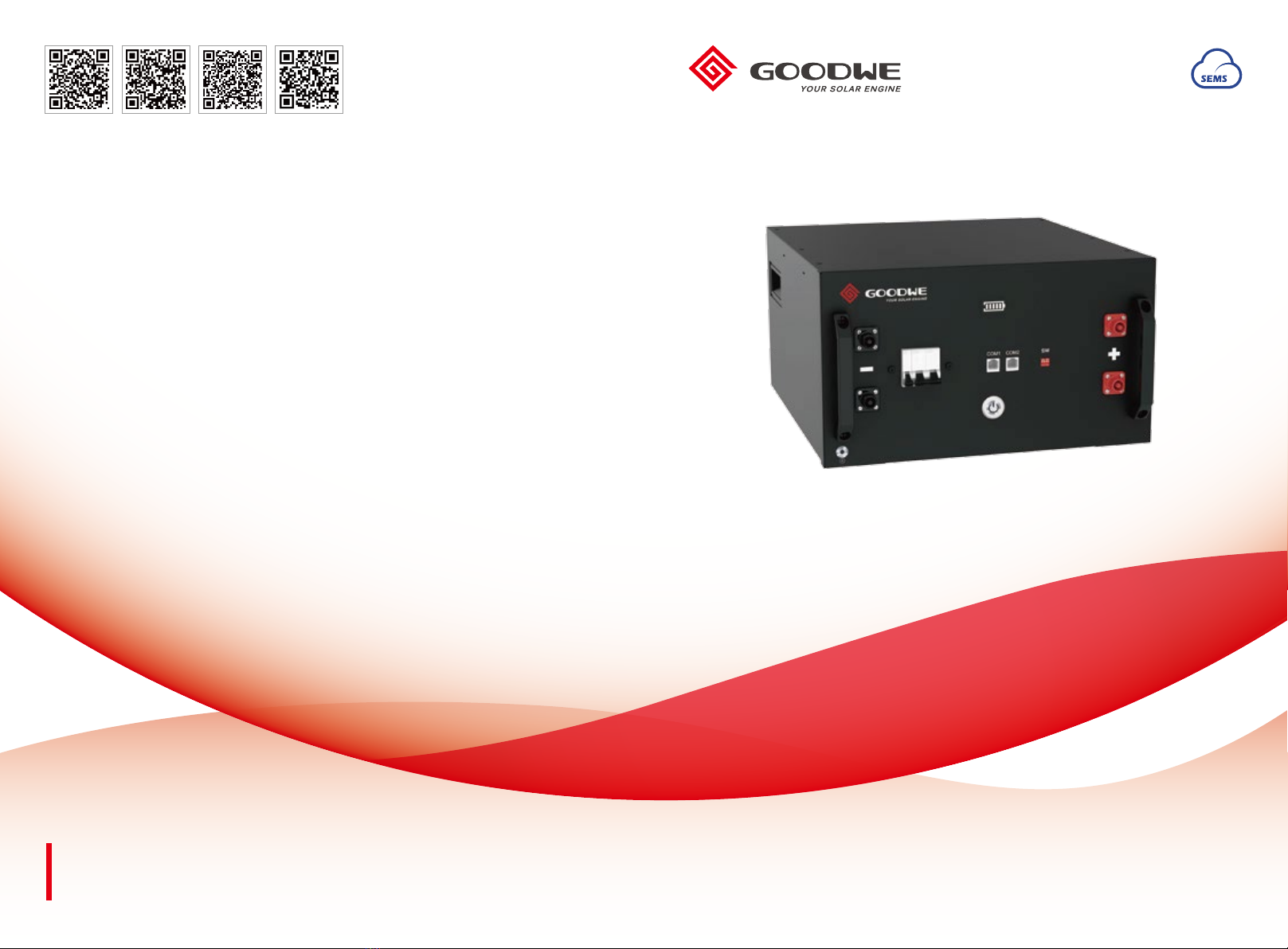
This manual introduces the installation and commissioning of SECU-A5.4L battery. Please
read through the manual and follow the instructions to use SECU-A5.4L battery.
This document is valid for the ******* from firmware version ******.
This document only contains brief information and may deviate from the real system.
Any Failure to follow this document instruction will make any manufacturer's warranty,
guarantee or liability null and void unless you can prove that the damage was not due to
non-compliance.
SECU-A5.4L battery is used with GoodWe ESA/ES/EM/SBP/BP series products. The battery
is designed for indoor use. But in a ESA system, the battery is protected by the ESA
enclosure, which could be used outdoors.
The system is not suitable for supplying life-sustaining medical devices. Please ensure that no
personal injury would lead due to the power outage of the system.
Alterations to the GoodWe system, e.g., changes or modifications are not allowed unless the
written permission of GoodWe is achieved.
The enclosed document is an integral part of this system. Keep the documentation in a conve-
nient, dry place for future reference and observe all instructions contained therein.
The instructions in this document may only be performed by qualified persons who must have
the following skills:
• Knowledge of how batteries work and are operated
• Knowledge of how an inverter works and is operated
• Knowledge of, and adherence to the locally applicable connection requirements, standards
and directives* (*the local standard for Australia is AS/NZS 5139:2019)
• Knowledge of, and adherence to this document and the associated system documentation,
including all safety instructions
• Training in dealing with the hazards associated with the installation and operation of electri-
cal equipment and batteries
• Training in the installation and commissioning of electrical equipment
The battery must be stored, installed or operated under secured environment, including:
• Ambient temperature shall be -10℃~ 50℃
• Keep it away from corrosive liquids or environment
• Keep it dry, away from any inductive liquid
• No high flammable or explosive materials nearby
Beware of a danger zone
This symbol indicates that the system must be additionally grounded if additional
grounding or equipotential bonding is required at the installation site.
Beware of electrical voltage.
Please it straight up, without inclination or upside down.
No more than five (5) identical packages being stacked on each other.
WEEE designation
Do not dispose of the system together with household waste but in accrodance with the
disposal regulations for electronic waste applicable at the installation site.
Handle with care
Keep the battery away from open flame or ignition sources.
Keep the battery modules away from children.
Do not short circuit.
Observe the documents
Observe all documents with the system.
Grounding conductor
This symbol indicates the position for connecting a grounding conductor.
Keep it dry
CE mark
The system complies with the requirements of the applicable EU directives.
5
02
01

Note:
· The battery is designed for GoodWe ESA, ES, EM, SBP, BP series energy storage system.
Before installation, make sure battery is not damaged and battery breaker is switched OFF. And
whole energy storage system is isolated from both AC and DC power.
· Before installation and cable connection, make sure battery is not damaged and battery breaker
is switched OFF. And whole ESA cabinet is isolated from both AC and DC power.
· Battery packs shall be connected in parallel.
· Each SECU-A5.4L unit has two sets of Power Cable Connector - and ﹢, which functions the
same. Any of the two sets could be used for power connection.
· Please make sure the positive and negative pole on both battery and inverter side not reversed,
otherwise the inverter or battery could be damaged.
· The unused battery connectors must be sealed with connector cover.
· When replacing or expanding the battery system, it is prohibited to connect the battery to the
systerm , please contact the after-sales service for processing.
· Please refer to the inverter user manual for specific connectors on each inverter. We just take
SBP and ESA series inverter as example to introduce the connection in this manual.
3 Product Overview
4 Cable Connection
4.1 Power Cable Connection
LED Indicator
Handle
Power Cable
Connector -
Power Cable
Connector +
Battery
Breaker Battery
Switch DIP Switch
Communication Port
Note:
The two COM ports on battery are of the same function.
The two Power Cable Connector + or - on battery are of the same function.
Power cable connection of SECU-A5.4L with ES, EM, SBP and BP inverters
Wi-Fi
Reset/Reload
SYSTEM
GRID
BACK-UP
ENERGY
COM
Wi-Fi
BATTERY
FAULT
BAT - BAT + BAT - BAT +
BATTERY +
BATTERY -
Battery 1
Inverter
Battery 6
.......
When SECU-A5.4L is used with ES, EM, SBP and BP series inverters,the power cable needs to
be prepared by the user, the recommended conductor cross-sectional area is 25mm2.
· Before installation and cable connection, make sure the whole ESA cabinet is isolated from both
AC and DC power.
· The cables between the battery and the inverter are connected in the same way. Please refer to
the "Cable connection of SECU-A5.4L with ES, EM, SBP and BP inverters".
· Open battery enclosure and install batteries and other component by sequence as below:
Power cable connection of single unit of SECU-A5.4L with ESA inverter
04
03

5.2 Powering on the battery system
Note: Please follow the instruction to turn on/off battery in case of any damage on battery modules.
In battery enclosure, battery cable and communication cable is preset
inside. Connect directly these cables on battery to the right position:
Note:
1. The two COM ports on battery are of the same function.
2. Battery packs shall be connected in parallel.
3. The cables between the battery and the inverter are connected in
the same way. Please refer to the "Cable connection of
SECU-A5.4L with ES, EM, SBP and BP inverters".
Battery Switch
TURN ON
Keep Pressing 2 seconds
TURN OFF
Keep Pressing > 5 seconds
5.1 Calibrating the DIP switch
• The DIP switches shall be configured differently between single piece battery and 2 battery
paralleling system.
• We just take SBP series inverter systerm as an example, the calibration method of the DIP
switch for ESA series inverter systerm is the same.
5. Battery Commissioning
1234
ON DIP
1234
ON DIP
1234
ON DIP
Function
Terminal Resistance Switch
GoodWe communication protocol Switch
DIP
2
3
Description
To recognize the last battery connected to inverter
To relize the communication between inverter and inverter unit part
ON
OFF
Communication cable connection of SECU-A5.4L with ESA inverter
Single Unit Of SECU-A5.4L System
2~6 Units Of SECU-A5.4L System
Communication cable connection of SECU-A5.4L with ES, EM, SBP and BP inverters
Wi-Fi
Reset/Reload
SYSTEM
GRID
BACK-UP
ENERGY
COM
Wi-Fi
BATTERY
FAULT
COM PORT COM PORT
BMS
Battery 1
Inverter
Battery 6
.......
Wi-Fi
Reset/Reload
SYSTEM
GRID
BACK-UP
ENERGY
COM
Wi-Fi
BATTERY
FAULT
Battery
Inverter
Wi-Fi
Reset/Reload
SYSTEM
GRID
BACK-UP
ENERGY
COM
Wi-Fi
BATTERY
FAULT
Battery 1
Battery 1~5 Battery 6
Inverter
Battery 6
.......
4.2 Communication Cable Connection
PIN
1
2
3
4
5
6
7
8
Colour
Orange and White
Orange
Green and White
Blue
Blue and White
Green
Brown and White
Brown
Function
N/A
N/A
N/A
CAN_H
CAN_L
N/A
N/A
N/A
1 2 3 4 5 6 7 8
When SECU-A5.4L is used with ES, EM, SBP and BP series inverters,the network cable needs
to be prepared by the user.RJ45 connector
Battery
Breaker
Battery
Switch
1. Check all cables are connected correctly.
2. Turn on the batery break.
3. Turn on all battery switches within 30 seconds
in the systerm. If it exceeds 30 seconds, there
will be a error alarm.
06
05

5.3 Setting the parameters of SECU-A5.4L On PV Master app
5.4 Observing the indicator status.
LED Indication
SOC Indicator
Operation
Indicator
Green, Blink 1s
Green, Blink 10s
Green, Blink 3s
Red, Blink 3s
Standby
Normal
Warning
Error
Operation Indicator
SOC < 5%
5%≤ SOC ≤25%
25%≤ SOC ≤50%
50%≤ SOC ≤75%
75%≤ SOC ≤95%
95%≤ SOC ≤100%
Operation Indicator
Operation LED
Green Blink
3 seconds
SOC LED Warning Description
Cell Temperature Difference
Battery High Temperature
Discharge Under Low Temperature
Charge Overcurrent
Discharge Overcurrent
Battery Over Voltage
Battery Under Voltage
Charge Under Low Temperature
Operation LED
Red
Blink
3 seconds
SOC LED
To make sure the battery communicates to inverter unit successfully, users have to use PV
Master to choose the right battery option on PV Master:
APP Installation And Connection:
Connect phone & Inverter
Wi-Fi SSID: Solar-WiFi***
Password: 12345678
Download
and install
PV Master
Note: If Battery Under Voltage happens during working status, by pressing battery switch for 5
times in 10 seconds, BMS will compulsively close MOS, so that inverter will detect battery open
circuit voltage to charge battery.
Select “SECU-A5.4L” on battery page in PV
Master Application
Notes:
1. Select wrong battery will lead to BMS
communication failure
2. Select wrong number of batteries the
input and output current will be limited
and the parameter indicated by the
converter is inconsistent with the actual
value of the battery.
3. For the complete commissioning of the
whole ESA system, please go to ESA
instruction.
Select Battery on PV master
6. Error Code and Warning Code
Warning Status
Select Battery Model
GoodWe
BYD
GCL
LG
PYLON
DYNESS
AlpahESS
eSTORE
Temperature Sensor
Failure
MOS Fault
Breaker Open
NO SN
Firmware Inconsistency
Multi Master Unit
MOS Over temperature
Error Description Solution
Reboot battery or contact aftersales
Reconnect communicatioin cable
Contact aftersales
Reconnect communication cable
Contact aftersales
Turn off battery for 2 hours
DIP Switch Status
difference
Turn Off battery and contact
aftersales
Keep same of DIP switch status and
reboot battery
Turn off and reboot all batteries in
30s
Slave Communication
Loss
Master Communication
Loss
play
App Store
Error Status
SECU-A5.4L*1
SECU-A5.4L*2
SECU-A5.4L*3
SECU-A5.4L*4
SECU-A5.4L*5
SECU-A5.4L*6 08
07

Model
Battery Type
System Weight
Dimensions(W x D x H )
Protection
Installed Capacity
Usable Energy
DOD
Nominal Voltage
Operating Voltage Range
Internal Resistance
Max. Charge current
Max. Discharge current
Operating Temperature Range
Humidity
Module Connect
Capacity Range
Usable Energy Range
Max. Charge Current
Max. Discharge Current
Monitoring Parameters
Communication
Certification
SECU-A5.4L
LiFePO4
49kg
400x226.2x484.2mm
IP20 (indoor)
5.4 kWh
4.8 kWh
90%
51.2 V
48 ~ 57.6 V
≤ 20 mΩ
50 A
50 A
-10 °C ~ 50 °C [1]
15% ~ 85%
6 Parallels
5.4/10.8/16.2/21.6/27/32.4 kWh
4.8/9.6/14.4/19.2/24/28.8 kWh
50A (1 Module) / 100A (2~6 Modules)
system voltage, current, cell voltage, cell temperature,
PCBA temperature
CAN
CE, UN38.3
7. Battery Parameters
Physical Parameters
Electrical Parameters
System Configuration
[1] When the temperature is below zero, the battery are not allowed to charge. When above 40℃,
the power output decreased.
8. Safety Instructions
The system has been designed and tested under international safety requirements. However, to
prevent personal injury and property damage and ensure long-term operation of the system, do
read this section carefully and observe all safety information at all times.
Battery Module Leakage
If the battery modules leak electrolyte, please avoid contact the leaking liquid or gas. If one is
exposed to the leaked substance, do these actions:
Inhalation: Evacuate the contaminated area, and seek for medical help immediately.
Eye contact: Rinse your eyes with clean water for at least 15 minutes and seek for medical help
immediately.
Skin contact: Wash the affected area thoroughly with soap and clean water, and seek for medical
help immediately.
Ingestion: Induce vomiting, and seek for medical help immediately.
Firefighting Measures
• In case of a fire, please make sure that a carbon dioxide extinguisher or Novac1230 or FM-200 is
nearby. Water cannot be used to extinguish the fire. (ABC is not effective for this battery firefight-
ing)
• Full protective clothing and self-contained breathing apparatus are required for the firefighters to
extinguish the fire.
Warning: Under >150℃environment, there is possibility that battery could explode
Handling and Storage Guide
• The battery modules and its components shall be protected from damage when it is in transporting
and handling
• Please take the weight of the battery module system into account during transportation and battery
module shall be lifted carefully
• Do not impact, pull, drag or step on the battery modules, either insert unrelated objects into any
part of the battery modules
• The battery module shall be kept away from a fire, water, strong oxidizers or solvents
• The battery modules cannot be stored in high temperature (> 60℃) or stored directly under the
sun, or in any high humidity environment.
• Do not use the battery modules if it is defective, or appears cracked, broken.
• Do not attempt to open, disassemble, repair, tamper with, or modify the battery modules without
official permission from GoodWe.
Warning: battery module damage may lead to electrolyte explosive air leakage, please
contact technical support immediately.
10
09

Warning of Electric Shock
It is danger to get electric shock when live components or DC cables are touched.
Disconnect the battery from voltage source before working on the device. Make sure of no any
manual operation under load. And do not touch non-insulated parts or cables. And wear suitable
protective equipment for all work on the system.
Warning: If battery is wetted, make sure it is not touched by hand, and contact technical
support
Surge Protection
Over voltages can be further conducted into the building or other connected devices in the same
network via network cables or other cables if there is no surge protection.
Ensure that the system is integrated into the existing surge protection.
9. Disclamer
→ All the information in this document is the property of GoodWe No part of this document could be
reproduced in any way for business use. Internal use is allowed.
→ GoodWe makes no representations or warranties express or implied, with respect to this
document or any of the equipment and/or software it may describe, including (with no limitation) any
implied warranties of utility, merchantability, or fitness for any particular purpose. All such represen-
tations or warranties are expressly disclaimed. Neither GoodWe nor its distributors or dealers shall
be liable for any indirect, incidental, or consequential damages under any circumstances.
→ The exclusion of implied warranties may not apply in all cases under some statutes, and thus the
above exclusion may not apply.
→ Specifications are subject to change without notice. Every effort has been made to make this
document complete, accurate and up-to-date. However, GoodWe may need to make some
improvements under certain circumstances without advance notice. GoodWe shall not be responsi-
ble for any loss caused by this document including, but not limited omissions errors, typographical
errors, arithmetical errors or listing errors in this document.
11
This manual suits for next models
1
Table of contents
Other Goodwe Camera Accessories manuals

Goodwe
Goodwe Lynx C Series User manual

Goodwe
Goodwe Lynx C Series User manual

Goodwe
Goodwe Lynx Home FH US Series User manual

Goodwe
Goodwe Lynx Home F Series User manual

Goodwe
Goodwe Lynx C Series User manual

Goodwe
Goodwe Lynx Home U Series User manual

Goodwe
Goodwe Lynx Home S Series User manual

Goodwe
Goodwe ET Series User manual

Goodwe
Goodwe Lynx Home U Series User manual

Goodwe
Goodwe Lynx Home F Plus+ Series User manual