goSmarthome X1-3G-RC-101 User manual

Printed in China
2016 V 1.0
GSM SMS

Table of Content
Get to Know Your System
Control Panel Installation
Working Status of Control Panel
Four Ways to Control System
Two Ways to Program the System
Included Accessories
Wireless Remote Control
Wireless P.I.R Motion Detector
Wireless Door/Window Sensor
Suggested Security System Setup
Wireless Accessories Enrolling, Clearing and Zone Setup
Connecting Wireless Accessories
(Wireless Accessories Enrolling)
Delete All Enrolled Accessories
Zone Setup
Connecting Wired Accessories
& Linkage Electronic Facilities
Programming System by SMS Text
SMS Text Operation
06
11
15
17
20
22
23
15
23
24
25
29
34
34
Frequently Asked Questions
49
02
Restore System to Default Setting
47 Specification
Quick Start Guide
04
13
14
24
31 Download APP
The Model:
2G PLUS
3G PLUS
2G GSM
GSM/WCDMA SMS Security Alarm System
GSM/SMS Security Alarm System
APP Setting
32

Wireless P.I.R. Motion Detector
The passive infrared motion detector is
designed to sense human movement.
It will detect the infrared radiation emitted from
intruders and send the signal to control panel.
Power Adapter
The power adapter is used to provide main power
for the control panel. The built-in 7.4V/1000mA
rechargeable battery enable the system working
for 16 hours in the event of a power failure.
It is a magnetic sensor for any opening like door
and window. It will send a wireless signal to the
control panel, when a door or window is opened.
Wireless Door/Window Sensor
Wireless Remote Control
The remote control allow you to control
your security system when you are away
or come back. When emergency happens,
press the emergency button to send an
emergency signal to the control panel.
The control panel is the brain of security alarm system, which is able to
communicate with all wireless sensors. When alarm occurs, the built-in
siren will hoot loudly to deter intruders. The system will notify the family
members by auto-dialing the preset phone numbers. The control panel
can receive command from remote control, SMS Text or Apps command,
and response to the alarm management in time.
Control Panel
Get to Know Your System
32

1
34
2
Follow these easy steps to install
your alarm system !
Using Remote Control
& Enrolling Test
Using Door Sensor
& Enrolling Test
Using P.I.R. Motion
Detector & Enrolling Test
Control Panel
Installation
Please remove all supplied contents from packaging
as below. If there' re anything missing, please return
to your place of purchase.
Control Panel
P.I.R. Motion
Detector
Remote Control
Bracket for
Motion Detector
Power Adapter
User ManualPlastic Plugs
& Screws
Batteries
3M
Double-sided
Tape
Wall-mounted
Bracket
Door/Window
Sensor
Quick Start Guide
54

Stay Arm
(Home Mode)
Disarm
Emergency Call
Arm
Using remote control to control the system when you are away or
come back home. Once there's an emergency situation, press
button once for help, both LED flashes once, the system immediately
goes in to an alarm condition. Press the Emergency Call Button,
if the alarm is activated, the remote control has been enrolled to the
system. Silence the siren by pressing Disarm Button on remote
control.
Using Remote Control & Enrolling Test
1 2
3
4
1
Control Panel Installation
Note! User have to store the phone number after SIM
Card is inserted. When detectors are triggered, the
alarm will be activated. The system will notify family
members by sending out SMS alert or calling. Even the
phone charge is overdue, the alarm will be activated
when detectors are triggered.
1. Gently open the battery bay cover.
2. Insert a SIM card fix it.
3. Insert power adapter’s barrel plug to adapter socket.
4. Slide the power switch to ON position.
5. Test enrollment of accessories.
6. Preset phone number after Sim Card is inserted so that the control panel
can be remotely controlled and when alarm is activated, it will send and
receive messages.
76

1
3
5
2
Using P.I.R. Motion Detector & Enrolling Test
1. Press the clip and open the case
2. Insert the battery properly, and then close the cover
3. Fasten the screw for case
4. Press arm button on remote control, the LED indicator
of control panel goes on.
5. Press the test button of P.I.R. motion detector
6. If the alarm is activated, the motion detector has
been enrolled to the system.
7. Silence the siren by pressing disarm button on
remote control.
46
1
4
3
Using Door Sensor & Enrolling Test
1. Open the case and install the battery properly.
2. Arm the system by pressing arm
button on remote control.
3. Depart the transmitter and magnet.
4. If the alarm is activated, the door sensor
has been enrolled to the system.
5. Silence the siren by pressing
disarm button on remote control.
Indicator goes on
to enter arming state.
Indicator light up in red
when transmitter and
magnet departed.
5
2
9
8

Working Status of Control Panel
Appearance
Green LED: AC Power
Yellow/Red LED: GSM Signal Indicator
White LED: Arming / Disarming
Red LED: Control Panel Status
Loudspeaker
SIM Card Slot
Power Switch
Adapter
Interface
Wired Interface
Enroll Button
Bracket
Hole
Tamper Switch
Features
∙ Frequency-Hopping Spread Spectrum technology for anti-interferance
∙ Two-way supervise the detector per 12 hours
∙ Change your remote control names
∙ 16 wireless zone(customized zone names to recognize the location)
∙Central Monitoring Station Setup
∙ Cellular communication by SMS Text or Apps, easy control
∙ Up to 50pcs sensors & 10 remote controls can be expanded
by auto learning
∙ 2 wired zone especially for smoke / gas / vibration / detector,
IR beams etc.
∙ Text to preset 3 groups of SMS number & auto-dial 5
groups of phone number and CMS number
∙ Internal siren sound and mute mode for optional
∙ Immediate SMS alerts for low battery of detectors,
power lost and power recovery
∙ Built-in 7.4V/1000mA battery ensure system working properly
for 16 hours after power lost
∙ Alarm output enable you to trigger the equipment as light,
TV etc. to deter the intruder
1110

Four Ways to Control Your
Security Alarm System
You can control your security alarm system by arming ,
disarming, stay arming or sending emergency signal via
remote control, SMS text command, phone remote
control and mobile apps.
Using a Remote Control:
The compact remote control is very easy to carry.
The multi-function key enable you to arm the system when you are away,
and disarm it when you come back. It's a simple and valuable tool which
can be reached easily for the emergency happens at your home.
Note! There’s no command for sending emergency call.
Using SMS Text Commands:
Please refer to Page 34 for details of SMS text command operation.
Disarm: Password#0
Arm: Password#1
Stay Arm: Password#2
Using Mobile Apps:
Please enter keyword“Ontips”to download the apps from the
App Store or Google Play. Fill in the Control Panel Name & Sim Card
Number of control panel to enter the user interface.
Note! There’s no command for sending emergency call.
Status LED Indication
Power/Signal LED Indication
AC Power On:
Green LED normally on
AC Power Off:
Green LED off
White LED ormally On: N
System armed
White LED Off:
System Disarmed
White LED Flashes ormally: N
System armed in stay mode.
GSM Network ACPowerOn ACPowerOff
Seaching GSM Network
GSM Network Found
Yellow LED flashes quickly
Yellow Power LED
flashes normally
Red LED flashes quickly
Red Power LED
flashes normally
Red LED On: Normally
System enters enrolling status
Red LED Flashes Normally
Alarm occurs.
Red LED Flashes Quickly:
Receive a SMS
1312

Wireless Remote Control
The compact and elegant remote control is easy to carry.
It is designed to fit on a key chain, a purse, a pocket
or to be hidden in the car sun visor.
This remote control act as multi-purpose key for arming,
disarming, arming stay, and emergency call.
LED Indication:
Included Accessories
Press stay button, then press or button within 3 arm arm disarm
seconds to enter into arming or disarming state in mute mode
without disturbing others.
Mute Mode
Two Ways to Program Your
Security Alarm System
Recommended! Simple and easy to use!
Method 1
Send a text of “?” to phone number of control panel,
the system will reply an operation guide message to your phone.
You can control the system by using the command codes listed.
Please refer to page 34 for command codes.
Method 2
Please enter keyword “Ontips” to download the apps from the
App Store or Google Play. Fill in the Control Panel Name & Sim Card
Number of control panel to start programming.
Remotely Control System by Phone
In the event the alarm, the alarm system will call the preset phone
number, user can pick up the phone , monitor the site, and remotely
control system by entering numbers. Users can call the alarm system
number, the system automatically enters monitoring status, users can
enter numbers to control it remotely.
4
1514

2
3
4
5
68
7
9
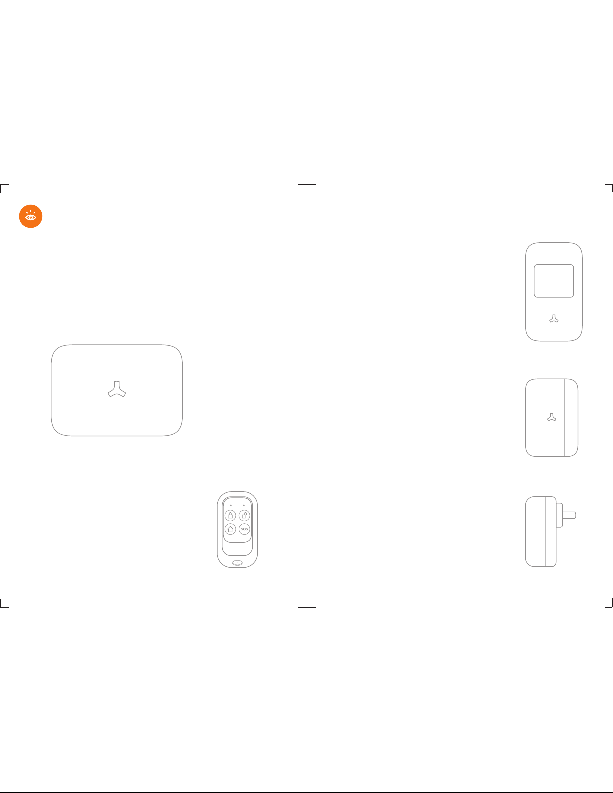
The passive infrared sensor with novel and beautiful style, perfect
streamline can be easily installed. It is designed to detect human
movement indoor. Adopted advanced fuzzy logic chip and intelligent
analysis distinguish signal between body movement and interference
to minimize false alarms. The built-in buzzer remind you low battery
state and event of tamper alarm, which ensure your safety.
1. Detection Window
2. LED Indicator
3. Learning Button
4. Clip
5. Battery Compartment
6. Zone Jumper
7. Buzzer
8. Tamper Switch
9. Infrared Sensor
Infrared Sensor: Detects the infrared rays released by human body motion.
Please do not touch the surface and keep it clean.
Once the case is opened ,the tamper switch will be triggered, Tamper Switch:
generating an alarm signal.
Status Indicator
LED flashed once:
Movement is detected.
LED flashes 5 times, and buzzer beeps 5 times:
Power on, tamper alarm, low battery indication.
If it’s in low battrey state,please replace it only
with1.5V/AA LR6 Manganese Dioxide Cell (
EXCELL, GP) immediately.
Features
Wireless P.I.R Motion Detector
1
55
Button Manual
Press the button to the system before leaving your home, arm arm
arming LED (left) flashes once, the siren beeps once to enter the
arming state. Any detectors triggered will activate the system to alarm
immediately.The system simultaneously calls the preset phone numbers.
Once Exit delay function is set, system will be delayed arming accordingly.
When you arm the system, in case of delay time less than 10 seconds,
control panel will beep once every second. While delay time more than
10 seconds, control panel will beep once every 2 seconds, the sound
will increase in tempo for the last 10 seconds for the "hurry up"
notification.
Arm
Press button before entering your homedisarming LED (right) disarm
flashes once.Then you are able to move freely in your home without
triggering the alarm. In the event of alarm, you can press this button
to disarm the system and silence the siren.
Disarm
Press the button, arming LED (left) flashes once, the siren beeps stay
once, system is in stay arm mode. The accessories in home mode are
disarmed, this allows the user to move freely at home, while the rest
of the system is fully armed, the accessories in normal zones will
activate an immediate alarm when triggered.
Stay Arm (Home Mode)
Once there's an situation, no matter what state the alarm emergency
system is in, press button once for help, both LED flashes once, SOS
the system immediately goes into an alarm condition and notify your
family.
Emergency Call
1716

110°
2m 4m 6m 8m
0m
0m
2m
1. Avoid mounting the detector close to places where heat changes fast
or air stream flows frequently. (ie. Air conditioner, tube light, oven, waver,
refrigerator etc.)
2. Avoid it facing to window which can be easily interfered
by complicated environment. (ie. sunlight, crowds, or
flowing cars etc.)
3. The product can reduce the possibility of accident,
but the user is advised to take all necessary precautions
for the safety and the protection of the property.
Detection Area
Side View
Top View
Connecting P.I.R. Motion Detector to Control Panel
The new-bought P.I.R. motion detector should be enrolled to the control
panel before use. For specified operation, please refer to the manual of
alarm system.
Notice
Walk Test:
1. When the power is on, the LED indicator flashes five times
and buzzer beeps five times to enter working state.
2. Walk across detection area and watch the LED indicator
to make sure it flashes once when detecting the
movement. After one detection, it will detect once every
one minute.
1
4
3
2
6
2.0~2.2m
5
Installation:
1. The motion detector should be installed in entry or exit which
intruder can easily enter.
2. The detector is more sensitive to cross-movement than to direct
movement. The performance of the detector is optimal when
detection direction is across the walking direction of intruders.
3. Press the clip, insert the battery properly, and then close the cover.
4. Using screws to fix the bracket of detector on the wall, attach the
detector to the bracket.
5. Keep LED indicator at the right direction. The fixing height isabout
2~2.2m from the ground.
6. Adjust installation height or bracket to change the detection
distance and angle.
Installation & Walk Test
Testing Mode: When the power is on, the LED indicator flashes 5 times,
and buzzer beeps 5 times to enter testing mode after 40 sec preheat.
In the test mode, it will enable the LED indicator to light and control panel
to alarm every time once a movement is detected. After the 20th detections,
LED lights light up 2 times to indicate that it is going to enter into sleep mode.
Sleeping Mode: The sleeping time of PIR approximately 4 minutes to save
power. No movement detected within 4 minutes, the PIR detector goes back
to the working mode. Once PIR is triggered, the PIR will light in red and alert
alarming. PIR will re-enter into sleep mode after 3 times detections during
the working mode. Any movement detected within 4 minutes , the PIR will
not light in red and the alarm will not be activated. And it will extend the
sleep time by another 4 minutes.
1918

1. Open the case and install the battery properly.
2. Sensor can be installed on door or window that open and close.
Make sure the installed position have been already cleaned.
3. Remove the paper strip of the double-sided tape on the back of
transmitter and magnet. Carefully mount the transmitter on the
door frame and the magnet on the door.
4. Keep LED Indication light at the right direction.
Make sure the magnet is on the right of the transmitter.
5. Place the transmitter in the desired location,
mount the magnet no more than 1cm away from the transmitter.
6. Avoid mounting sensors in areas with a large quantity
of metal and electric wiring.
Installation:
Note! The door sensor is set in Normal Zone1 as default.
It will cause on immediate alarm if the magnet depart from
the transmitter more than 2cm in arming state.
<1cm
The Door/Window Sensor can be installed on doors,
windows and any other objects that open and close.
The sensor transmits signal to control panel when the
magnet mounted near the sensor is moved away.
The tamper protection ensures that sabotage attempts
to move the sensor will result in an alarm activation.
2
34
5
7
61. Transmitter
2. LED Indicator
3. Magnet
4. Battery Compartment
5. Zone Jumper
6. Buzzer
7. Tamper Switch
Working Status:
Tamper Alarm: Once intruder attempts to move the sensor,built-in buzzer
beeps.The control panel will send tamper alarm message to user at the first
time.
Please follow manual of alarm system for zone1 setup. Zone Jumper:
The door sensor is set in normal zone as default.
1LED flashes once:
Door or window is opened.
and the transmitter sends signal to the control panel.
LED flashes 5 times, and buzzer beeps 5 times:
Tamper alarm, low battery indication. If it’s in low
battery state,please replace it only with1.5V/AA LR6
Manganese Dioxide Cell (EXCELL, GP) immediately.
55
Wireless Door/Window sensor
21
20

2
4
1
1. Press the Enroll Button , the control panel enters enrolling
status, the LED lights up in red. ( Press again the Enroll Button
within 20 seconds to exit enrolling state.)
2. Connecting PIR Sensor to Control Panel:
Press the test button on the back of PIR Sensor.
3. Connecting Remote Control to Control Panel:
Press any button on the remote control.
4. Connecting Door Sensor to Control Panel:
Depart the transmitter and magnet
5. System beeps once, the LED light flashes once,
the enrollment is successful.
If system beeps twice and the LED light flashes once,
the accessories have been enrolled before.
If three beeps are heard and LED light flashes once,
the storage is full.
Wireless Accessories Enrolling
Note! Wireless siren is not included as wireless
accessory.For specific details, Please refer to the
manual of siren. If accessories zones are changed,
you have to reconnect the accessories to the control panel.
User can not trigger accessory ‘s tamper switch button to
enroll into system.
Wireless Accessories Enrolling,
Clearing and Zone Setup
3
Suggested Security System Setup
Garage
Bath
Walk-in Closet
Closet
Bedroom
Terrace
Living Rooms
DiningRoom
Boxroom
Bath
Walk-in Closet
Library
Closet
Master
Bath
Closet Master
Bedroom
Eat-in kitchen
Foyer
Walk-in Closet
23
22

Zone Setup
Door/Window Sensor
Normal Zone Setup
The accessory is set in normal zone (immediate alarm zone) as default.
Once triggered in arming state, the system will receive signal and
activate the alarm immediately.
PCB Diagram-Zone Jumper
PIR Motion Detector
Wireless Zone 4
2
1
Delete Enrolled Wireless Accessories
Press and hold the enroll button for 6 seconds until one
beep is heard. All enrolled wireless accessories will be
deleted.
Press the tamper switch continuously for 5 times until one
long beep is heard.
All preset number will be deleted at once and the system
is restored to default setting successfully.
Restoring operation will not delete the enrolled Note!
accessories.
Restore System to Default Settings
25
24

Stay Mode (Home Mode) Zone Setup
Home Mode2
(Wireless Zone 2)
Home Mode1
(Wireless Zone 1)
Stay mode is known as "part arm". When system is stay armed,
the accessories in home mode are disarmed. This allows the user to
move freely at home. While the rest of the system is full armed,
the accessories in normal zones will activate an immediate alarm
when triggered.
Single Delay Zone Setup
If the Exit/ Entry Delay Time is set, accessories in single delay zone ,
will be delayed for arming and alarming, Home Mode Zone accordingly.
But accessories in Normal Zone Home Mode Zone and 24-Hour Zone
will not be delayed.
Single Delay Zone
(Wireless Zone 3)
Note! PIR Motion Detector is set in stay (home) mode zone as default.
Door/Window Sensor is set in Normal Zone 4 as default.
Wireless Zone5 Wireless Zone 6 Wireless Zone7 Wireless Zone 8
Wireless Zone9 Wireless Zone 10 Wireless Zone11 Wireless Zone 12
Wireless Zone13 Wireless Zone 14 Wireless Zone15
(24 Hours Zone 1)
Wireless Zone 16
(24 Hours Zone 2)
2726

Connecting Wired Accessories & Linkage
Electronic Facilities
G D+ D- V V S G N
LEARN
24-Hour Zone 1 24-Hour Zone 2
24-Hour Zone Setup
No matter what state the alarm system is in, once the accessories in
24-Hour zone are triggered, the control panel will get the signal and
alarm immediately.
Note! It’s highly recommended to set the smoke detector,
gas detector and perimeter detectors at 24-Hour Zone.
(Wireless Zone 15) (Wireless Zone 16)
29
28

AC
Wired Accessories:
It supports 2 groups of wired accessories.
Please choose the wired sensor types after connected.
Connect Wired Sensor to Wired Zone 1
Connect N.C. Type Door Sensor to Wired Zone. One cable for the IN1
or IN2 block, another for GND block.
Send text 74 to choose wired sensor type to be N.C.
Test if the alarm occurs when wired sensor is trigger.
Connect Wired Siren
Connect the Negative Pole to GND block,
the Positive Pole to N.O block.
Then link COM block and +12V block.
Linkage AC Electronic Facilities:
It is able to turn on electronic facilities like
lights, or fences to deter the intruder
immediately in the event of alarm.
Note! The max output of Built-in Battery is 8.4V.
When wired siren is connected, please make sure
the power supply is on for working properly.
Ground
Power Output for
Wired Accessories
Normal Close
Normal Open
Common Port
Ground
Wired Interface 2
Wired Interface 1
Download APP
PleasedownloadtheAPPfromAppStoreorGooglePlayby
enteringthekeyword"Ontips".
Ontips
31
30

Please select model before you create account
Store Alarm Phone Numbers
Change Zone Names
Time De lay
Change Access Code
Language Settings
Zone 1
Zone 2
Zone 3
Zone 4
Zone 5
Zone 6
Zone 7
Zone 8
Zone 9
Zone 10
Zone 11
24H Zone 15
24H Zone 16
7
8
9
10
11
Alarm Type
Wired Sensor Type
Keyfob SMS Alert
Supervion for Door Sensor
Change Keyfob Name
Uesr ID
Report Upload
GSM Signal Strength Monitor
3332

Disarm
Arm
Arm Stay
1234#0
1234#1
1234#2
System Disarmed.
System Armed in Away Mode.
System Armed in Stay Mode.
Send this operation code
from your cell phone:
Send this operation code
from your cell phone:
Send this operation code
from your cell phone:
SMS reply you will receive:
?
It’s easy for users to manage functionality through your cell phone
by sending SMS text commands listed as below. Send a text of to “?”
the SIM card number of control panel , the system will reply you a main
operation guide menu.
Send (original password is 1234) to setup, “password#command code”
for example to store phone numbers.“password#5”
Programming System by SMS Text Operation
Note!Users have to store the phone number after Sim Card is inserted so that
the control panel can be remotely controlled and when alarm is activated, it will send
and receive messages.
Disarm: 0
Arm Away: 1
Arm Stay : 2
Status Inquiry: 3
Alarm Management: 4
Store Phone Numbers: 5
Change Zone Name: 6
Other Setup: 7
System Language: 8
Electrical Facility Control: 9
Change Keyfob Name:10
SMS reply you will receive:Send this operation code
from your cell phone:
System disarmed with all
detectors deactivated.
System fully armed with
all detectors activated.
The Arm/Stay function will arm the
system with sensors in normal zone
activated immediately, but sensors
in home mode zone disabled.
SMS Text Operation
3534

Status Inquiry Alarm Management
Turn Off the Local Siren
1234#4
41
42
Send this operation code
from your cell phone:
Send this operation code
from your cell phone:
SMS reply you will receive:
Turn On the Local Siren
(Please Text Below Command Code to
Manage the System)
41: Turn On the Local Siren
42: Turn Off the Local Siren
43: Two-way Talk
Local Siren: On
Local Siren: Off
Send this operation code
from your cell phone:
SMS reply you will receive:
System Status Inquiry
1234#3
31
32
SMS reply you will receive:
(Please Text Below Command Code
to Inquiry the System Setting)
31: Control Panel Status
32: IMEI Information
IMEI Information Inquiry
IMEI No.:**** **** **** ****
IMEI is International Mobile Equipment Identity number, consist of 15 digits “electronic serial
number” which is unique to identify valid devices. Every alarm panel will be assembled with
an unique IMEI number to make sure it’s original from manufacturer.
Send this operation code
from your cell phone:
Send this operation code
from your cell phone:
Send this operation code
from your cell phone:
SMS reply you will receive:
System Status: Away Armed
AC Power: On
Alarm Type: Audible
Local Siren:Off
SMS Alert for Keyfob Operation: Off
Wired Sensor Type: N.C.
System Status:
Away Armed/Disarmed/Stay Armed
AC Power: On/Lost/Recovered
Alarm Type: Audible /Silent
Local Siren OFF/ON
SMS Alert for Keyfob Operation: On/Off
Wired Sensor Type: N.O/N.C
43 Send ‘43’ to the SIM card number.
The control panel will call back.
You can now listen in and have a
two-way talk.
3736
Table of contents
Popular Security System manuals by other brands

Hiltron security
Hiltron security PROTEC5X user manual

ITI
ITI ITI UltraGard owner's manual

NAPCO
NAPCO NETLINK datasheet

Zicom
Zicom Z.HA.HA.HOOT.ATOUCH.SIREN user manual

Nortek Security & Control
Nortek Security & Control Linear BluePass 820-00001 installation guide

Whelen Engineering Company
Whelen Engineering Company B6LED Series installation guide