GPI MR 5-30 User manual

General Information������������������ 2
Safety Instructions�������������������� 2
Installation �������������������������������� 2
Operation���������������������������������� 3
Calibration �������������������������������� 4
Maintenance����������������������������� 4
Troubleshooting������������������������ 5
Specications ��������������������������� 5
Illustrated Parts List������������������ 6
Parts and Service��������������������� 7
TABLE OF CONTENTS
5252 East 36th Street North
Wichita, KS USA 67220-3205
TEL: 316-686-7361
FAX: 316-686-6746
SAVE THESE INSTRUCTIONS
MR 5-30 Aviation
Fuel Meter
Owner’s Manual
To the owner…
Congratulations on receiving your GPI
MR5-30Meter�Wearepleasedtoprovide
you with a meter designed to give you
maximum reliability and efciency.
Ourbusinessisthedesignmanufacture,
and marketing of liquid handling,
agricultural,andrecreationalproducts�We
succeedbecauseweprovidecustomers
withinnovative,reliable,safe,timely,and
competitively-priced products� We pride
ourselvesinconductingourbusinesswith
integrity and professionalism�
Weareproudtoprovideyouwithaquality
product and the support you need to
obtainyearsofsafe,dependableservice�
President
Great Plains Industries, Inc
10/11 Rev� - 922092-09

GENERAL INFORMATION
The purpose of this manual is to assist
you in installing, operating and main-
taining your mechanical fuel meter�
Please take a few moments to read
these instructions before installing and
operating your fuel meter�
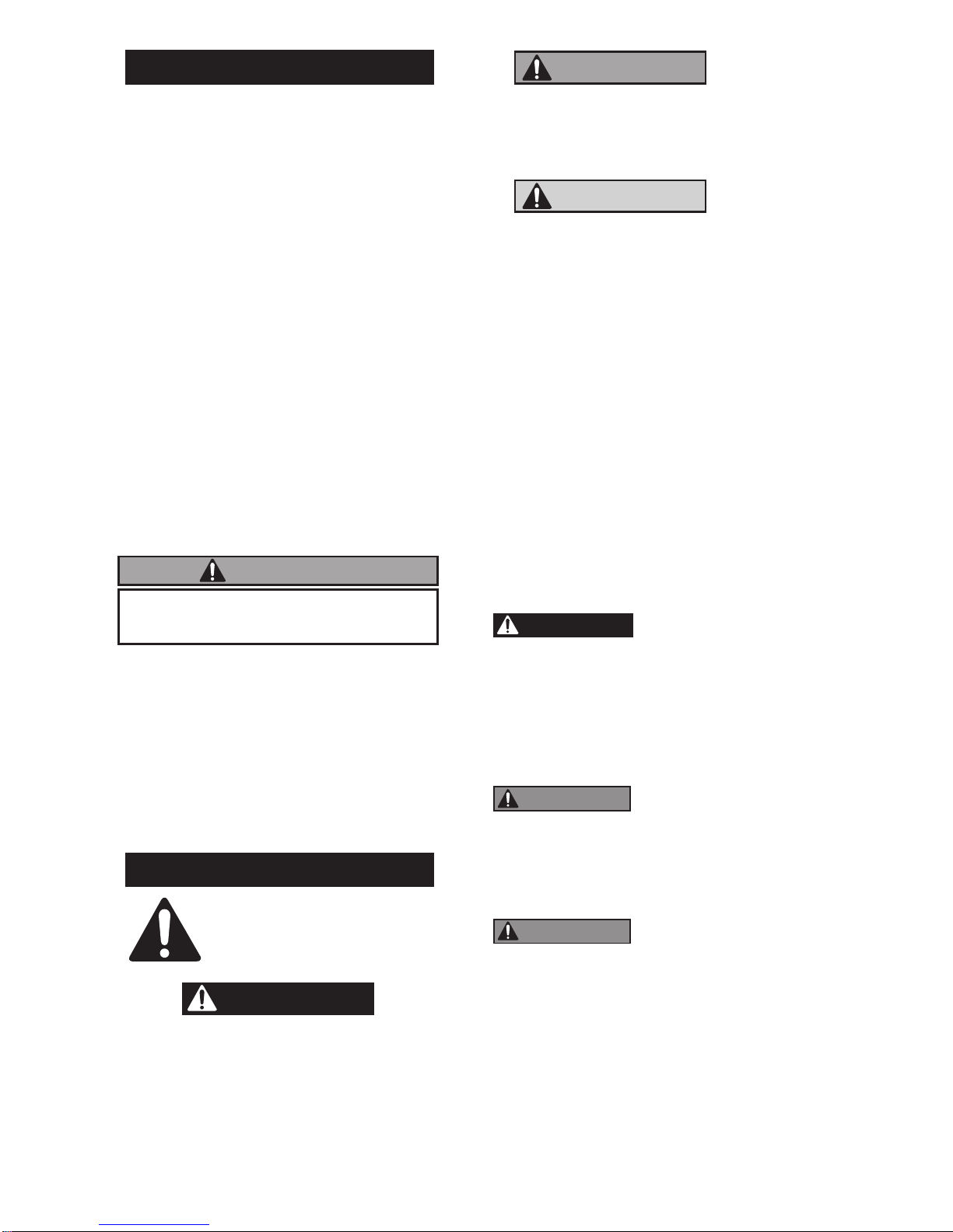
The MR 5-30 Mechanical Fuel Meter is
designed for the eld measurement of
thin viscosity petroleum fuels only and
intended for use with pump systems
in the 5 to 30 GPM or 19 to 114 LPM
ow range (not intended for gravity
ow systems). Using mechanical gears,
these meters translate ow data from a
nutatingdiscintocalibratedunitswhich
are indicated on the face of the meter�
Thismeterisfactorycalibrated forkero-
sene grade (JET A). Field calibration
feature is available for other uids, see
Calibration section�
For ground-based refueling only.
Do not use in or on the aircraft.
Use this meter with aviation gasoline
(AVGAS 100LL) and kerosene grade
(JET A).
Do not use this equipment for dis-
pensing any uids other than those
for which it was designed. To do so
may damage the meter and will void
the warranty.
SAFETY INSTRUCTIONS
The following safety
alert symbols are used
in this manual.
DANGER
DANGER indicates a hazardous
situation which, if not avoided, will
result in death or serious injury.
WARNING
WARNING indicates a hazardous
situation which, if not avoided, could
result in death or serious injury.
CAUTION
CAUTION indicates a hazardous
situation which, if not avoided, may
result in minor or moderate injury.
It is your responsibility to:
• know and follow applicable na-
tional, state and local safety codes
pertaining to installing and operat-
ing electrical equipment for use
with ammable liquids.
• know and follow all safety precau-
tions when handling petroleum
fuels
• ensure that all equipment op-
erators have access to ade-
quate instructions concerning
safe operation and maintenance�
1�
DANGER
Observeprecau-
tions against re or explosion when
dispensing fuel� Do not operate
the meter in the presence of any
source of ignition including run-
ning or hot engines, lighted ciga-
rettes, or gas or electric heaters�
2�
WARNING
Anycomponents
such as hose, nozzle, or pump
added to your meter must be
statically grounded and approved
for use with petroleum fuels�
3�
WARNING
Avoidprolonged
skin contact with petroleum fuels�
Use protective goggles, gloves,
and aprons in case of accidental
splashing or spillage� Change
saturated clothing and wash skin
contact areas promptly with soap
and water�
2
WARNING

INSTALLATION
Before installing your meter, review the
safety instructions given above� Exam-
ine your meter to make sure there are
no visible signs of shipment damage�
Plan your meter installation by review-
ing the following procedures� Your sys-
tem mustbe mounted ona vented tank�
Ifthe tank isunvented, your localdealer
ordistributorcansupplya pressurecap�
If the meter is located in a rigid piping
system where the uid is trapped (for
example, by gravity, valves or nozzles)
thermal expansion of the fluid can
createpressurespikesthatcandamage
a meter�
Installathermal reliefvalve orotherwise
allow for thermal expansion of the uid.
Prior to installation, determine the tting
angledesired andwhetherhorizontal or
vertical orientation is required�
Rotate Fittings
To rotate inlet and/or outlet fittings,
remove the two nuts and bolts that
secure each tting. Rotate the tting to
the desired orientation� Make sure the
O-ring is fully seated� Tighten the nuts
and bolts snugly�
C
hange Orientation
1� Pull the knob to remove from unit�
Remove screws that hold bezel in
place and set aside�
2� Remove the two screws that hold
the faceplate in place and remove
faceplate. (Figure 1)
3� Remove two screws to release
the counter assembly. (Figure 2)
4� Remove the bevel gear from the
center of the coverplate� Remove
the eight pairs of nuts and bolts
that hold the coverplate assembly
in place�
5� Now you can rotate the coverplate
to the desired orientation�
Reassemble in reverse order,
making sure the O-ring is fully
seated�Torqueeightnuts andbolts
to 60 - 72 in-lb�
Meter Installation
1� Remove protective plugs from the
meter inlet and outlet ports�
2� Wrap threaded male connections
with thread tape or use a pipe
sealant compound compatible with
petroleum fuels� We recommend
thread sealant at the inlet tting in
horizontal orientation�
3� Install the meter on the pump using
an appropriately sized nipple� The
meter’s ow path is marked on the
housingexteriorwithanarrowpoint-
ing toward the outlet port�
4� Installothersystem componentson
the meter and tighten snugly�
OPERATION
ALWAYS FOLLOW SAFETY
PRECAUTIONS WHEN OPERATING
THIS EQUIPMENT. REVIEW THE
SAFETY INSTRUCTIONS. Before
each use, visually check the meter to
ensure it is securely connected to other
system components and there is no
leakage�Promptly wipespilled fuelfrom
the meter’s exterior and other system
components�
3
Figure 1
Figure 2

4
b� Ifthe meter registeredlessthan
thequantityinthecontainer,turn
thecalibration screw clockwise�
If the meter registered more
than the amount in the
container, turn the calibration
screw counterclockwise�
5� Empty the calibration container
and repeat steps 2 to 4 until the
meter registers the quantity in the
container�
6� Installthe nylon washerand calibra-
tion screw cover�
The meter’s strainer should be cleaned
atregular intervals,especially whenlow
ow is detected.
Clean or Replace Strainer
1� Remove the nuts and bolts at the
inlet fitting� Remove the fitting,
O-ring, and strainer�
2� Using a fine brush, clean the
strainer� Replace the strainer as
necessary�
3� Wipe clean the inlet, housing, and
O-ring groove� Coat the O-ring with
oil or light grease� Make sure the
O-ring is fully seated� Replace the
strainer�
4� Position the inlet tting in the desired
orientationandtightenthe nuts and
bolts to 60 - 72 in-lb�
Figure 4
The large meter display represents the
BatchTotalforeachfueldelivery�Before
dispensing,resettheBatchTotaltozero
by turning the knob. (Figure 3)
The small display represents the
CumulativeTotalofallfueldeliveries
and cannot be reset�
CALIBRATION
The meter is accurately calibrated at
the factory for use with kerosene grade
(JET A)� Due to differences in viscosity
and owrates, the meter may require
recalibration to measure other fuels or
to adjust for inaccuracies�
1� Purge air from the meter and fuel
system by dispensing fuel into a
container until a full ow occurs.
Close the nozzle�
2� Reset the meter counter to zero by
turning the reset knob. (Figure 3)
3� Pump into a graduated calibration
container to a specied quantity.
For the greatest accuracy, be sure
the container is placed on a level
surface and a consistent ow rate is
used� When topping off the calibra-
tioncontainer,useaquick-openand
quick-close method until the mark
is reached�
4� Compare the meter display to the
quantity in the container� If the
meter display does not register the
quantityon the container,adjustthe
meter by performing the following:
a� Gain access to the recessed
calibration screw by turning the
calibration screw cover and seal
counterclockwise� Remove the
cover and nylon washer. (Figure 4)
MAINTENANCE
Figure 3

5
TROUBLESHOOTING
Symptom Probable Cause Corrective Action
A� Meter counter does 1� Broken counter assembly� Replace counter�
not operate. (Nor-
mal fuel delivery) 2. Foreign material in counter Remove and clean counter
assembly or nutator assembly� assembly or nutator assembly�
3� Broken nutator disc pin or Install new nutator assembly�
defective nutator assembly�
4� Missing or worn bevel gear� Replace bevel gear�
B� Meter counter does 1� Clogged strainer in meter� Clean or replace strainer�
not operate�
(Little or no fuel ow) 2� Other system components Check all system components
malfunctioning� tank to nozzle for clogs and/or
malfunctions�Repairasnecessary�
3� Foreign material in nutator Remove and clean nutator
assembly� assembly�
C� Fuel leakage� 1� Leakage at counter drive shaft� Replace coverplate assembly�
2� Leakage between coverplate Remove coverplate and inspect
and housing� for damaged, missing or
incorrectly seated seal� Replace
as required�
3. Leakage at ttings. Remove ttings and inspect for
damaged, missing or incorrectly
seatedseals�Replaceasrequired�
4� Leakage at threads� Remove meter and reseal all
threaded connections with
thread tape or pipe thread
sealing compound approved
for use with ammable liquids.
SPECIFICATIONS
Gallon Models Litre Models
Unit of Measure U.S. Gallon Litre
Flow Range 5 to 30 GPM 19 to 114 LPM
Typical Accuracy ± 2% ± 2%
Type Nutating Disc Nutating Disc
Housing Material Aluminum Aluminum
Maximum Working Pressure 50 PSIG 3�4 bar
Inlet/Outlet Fitting Size 1" 1"
Threads NPT NPT
Maximum Batch Total 999�9 9999
Maximum Cumulative Total 9,999,999�9 99,999,999
Approximate Ship Weight 8�1 lbs� 3�7 kg
Maximum Dimensions: Width: 8�0 inches 20�3 cm
Height: 7.0 inches 17.8 cm
Depth: 6�0 inches 15�2 cm
Note: Accuracy is factory calibrated using kerosene grade (JET A). Field Calibration
is available on all models�

6
ILLUSTRATED PARTS LIST
Kits and Accessories
126530-09 Seal Kit - includes one housing O-ring and two tting O-rings
126530-08 Nutator Assembly Kit - includes hardware
126530-06 Bevel Gear Kit
126530-04 Gallon Counter Assembly Kit - includes counter assembly
and hardware
126530-05 Litre Counter Assembly Kit - includes counter assembly
and hardware
126530-02 GallonFaceplateKit-includesfaceplate,decalandhardware
126530-03 LitreFaceplate Kit - includesfaceplate,decal and hardware
126530-01 Bezel Kit -includes hardware
126530-07 Knob Assembly Kit
126530-12 Fitting Kit for 3/4-inch NPT (2 Fittings, 2 Fitting O-Rings, 1
strainer and hardware)
126530-13 Fitting Kit for 3/4-inch BSPP (2 Fittings, 2 Fitting O-Rings,
1 strainer and hardware)
126530-14 Fitting Kit for 1-inch NPT, (2 Fittings, 2 Fitting O-Rings,
1 strainer and hardware)
Part No� Description
A
B
C
D
E
F
G
H
I
J

7
PARTS AND SERVICE
For warranty consideration, parts, or other
serviceinformation,contactyourlocaldistributor.
If you need further assistance, please contact
GPI Customer Service Department in Wichita,
Kansas during normal business hours at
1-800-835-0113.
To obtain prompt, efcient service, always be
prepared with 1.) the model number of your
meter,2.)themanufacturingdatelocatedonthe
back of the meter, and 3.) specic information,
asnecessary,obtainedfromtheIllustratedParts
List.Forwarrantyworkalwaysbepreparedwith
proof of purchase date.
Please contact GPI before returning any parts.
It may be possible to diagnose the trouble and
identify needed parts without returning parts.
GPIcanalsoinformyouofanyspecialhandling
requirements you will need to follow covering
the transportation and handling of fuel transfer
equipment. Before packing for shipment, make
surethemeteristhoroughlydrainedandfreeof
fuel and vapors.
Kits and Accessories, continued
Kit
No� Part No.Description
Donot return meters or parts without
specific authority from the GPI
Customer Service Department�
Due to strict regulations governing
shipment of ammable liquids, meters
may be refused and returned to the
sender if sent without authorization�
126530-15 Fitting Kit for 1-inch BSPP (2 Fittings, 2 Fitting O-Rings,
1 strainer and hardware)
126530-16 Fitting Kit for 1-1/2 inch NPT (2 Fittings, 2 Fitting
O-Rings, 1 strainer and hardware)
126530-17 Fitting Kit for 1-1/2 inch BSPP (2 Fittings, 2 Fitting
O-Rings, 1 strainer and hardware)
126530-11 Calibration Screw Kit - includes screw, washer O-ring
& cover
126530-10 Hardware Kit - includes O-rings, strainer, nuts & screws
CAUTION

GPI is a registered trademark of Great Plains Industries, Inc�
© 2011 GREAT PLAINS INDUSTRIES, INC., Wichita, KS.
Printed in U.S.A.
5252 East 36th Street North
Wichita, KS USA 67220-3205
TEL: 316-686-7361
FAX: 316-686-6746
Limited Warranty Policy
Great Plains Industries, Inc� 5252 E� 36th Street North, Wichita, KS USA 67220-3205, hereby provides a limited
warranty against defects in material and workmanship on all products manufactured by Great Plains Industries,
Inc� This product includes a 2 year warranty from date of purchase as evidenced by the original sales receipt�
A 30 month warranty from product date of manufacture will apply in cases where the original sales receipt is
not available� Reference product labeling for the warranty expiration date based on 30 months from date of
manufacture� Manufacturer’s sole obligation under the foregoing warranties will be limited to either, at Manufac-
turer’s option, replacing or repairing defective Goods (subject to limitations hereinafter provided) or refunding
the purchase price for such Goods theretofore paid by the Buyer, and Buyer’s exclusive remedy for breach of
any such warranties will be enforcement of such obligations of Manufacturer� The warranty shall extend to the
purchaser of this product and to any person to whom such product is transferred during the warranty period�
This warranty shall not apply if:
A. the product has been altered or modied outside the warrantor’s duly appointed representative;
B� the product has been subjected to neglect, misuse, abuse or damage or has been installed or
operated other than in accordance with the manufacturer’s operating instructions�
To make a claim against this warranty, contact the GPI Customer Service Department at 316-686-7361 or
800-835-0113� Or by mail at: Great Plains Industries, Inc�
5252 E� 36th St� North
Wichita, KS, USA 67220-3205
GPI will step you through a product troubleshooting process to determine appropriate corrective actions�
GREAT PLAINS INDUSTRIES, INC., EXCLUDES LIABILITY UNDER THIS WARRANTY FOR DIRECT, IN-
DIRECT, INCIDENTAL AND CONSEQUENTIAL DAMAGES INCURRED IN THE USE OR LOSS OF USE OF
THE PRODUCT WARRANTED HEREUNDER.
The company herewith expressly disclaims any warranty of merchantability or tness for any particular purpose
other than for which it was designed�
This warranty gives you specic rights and you may also have other rights which vary from U.S. state to U.S. state.
Note: In compliance with MAGNUSON MOSS CONSUMER WARRANTY ACT – Part 702 (governs the resale
availability of the warranty terms).
10/11 Rev� - 922092-09
Table of contents
Other GPI Measuring Instrument manuals
Popular Measuring Instrument manuals by other brands

REED
REED R3030: R3100 instruction manual

WATANABE ELECTRIC INDUSTRY
WATANABE ELECTRIC INDUSTRY A7X18-X Operation manual

Acrel
Acrel ADL400 Installation and operation instruction

GOMETRICS
GOMETRICS T214 user manual

MarMonix
MarMonix MCA-207 instruction manual

Textron
Textron Greenlee CM-600 instruction manual