Rev. A 921499012
• know and follow all safety precautions when handling
petroleum fuels.
• insure that all equipment operators have access to
adequate instructions concerning safe operating and
maintenance procedures.
Observe all safety precautions concerning safe handling
of petroleum fuels.
To ensure safe operation, all fuel transfer systems must
be properly grounded. Proper grounding means a continu-
ous metal-to-metal contact from one component to the
next, including tank, bung, pump, meter, lter, hose and
nozzle. Care should be taken to ensure proper grounding
during initial installation and after any service or repair
procedures. For your safety, please take a moment to
review the warnings below.
To prevent physical injury, observe precautions against
re or explosion when dispensing fuel. Do not operate
the system in the presence of any source of ignition
including running or hot engines, lighted cigarettes, or
gas or electric heaters.
Observe precautions against electrical shock when oper-
ating the system. Serious or fatal shock can result from
operating electrical equipment in damp or wet locations.
Inspect external pump wiring regularly to make sure it
is in good condition. To avoid electrical shock, use extra
care when connecting the pump to power.
Avoid prolonged skin contact with petroleum fuels. Use
protective goggles, gloves and aprons in case of splash-
ing or spills. Change saturated clothing and wash skin
promptly with soap and water.
Observe precautions against electrical shock when
servicing
the pump. Always disconnect power before repairing
or servicing. Never apply electrical power to the system
when any of the coverplates are removed.
If using solvent to clean pump components or tank,
observe the solvent manufacturer’s recommendations
for safe use and disposal.
INSTALLATION
This pump is designed to self-prime with dry gears.
Expect suction lift as follows:
Manual Nozzle: 5.5 feet (1.7 m) with diesel
6.7 feet (2.1 m) with gasoline
Automatic Nozzle: 4.8 feet (1.5 m) with diesel
5.8 feet (1.8 m) with gasoline
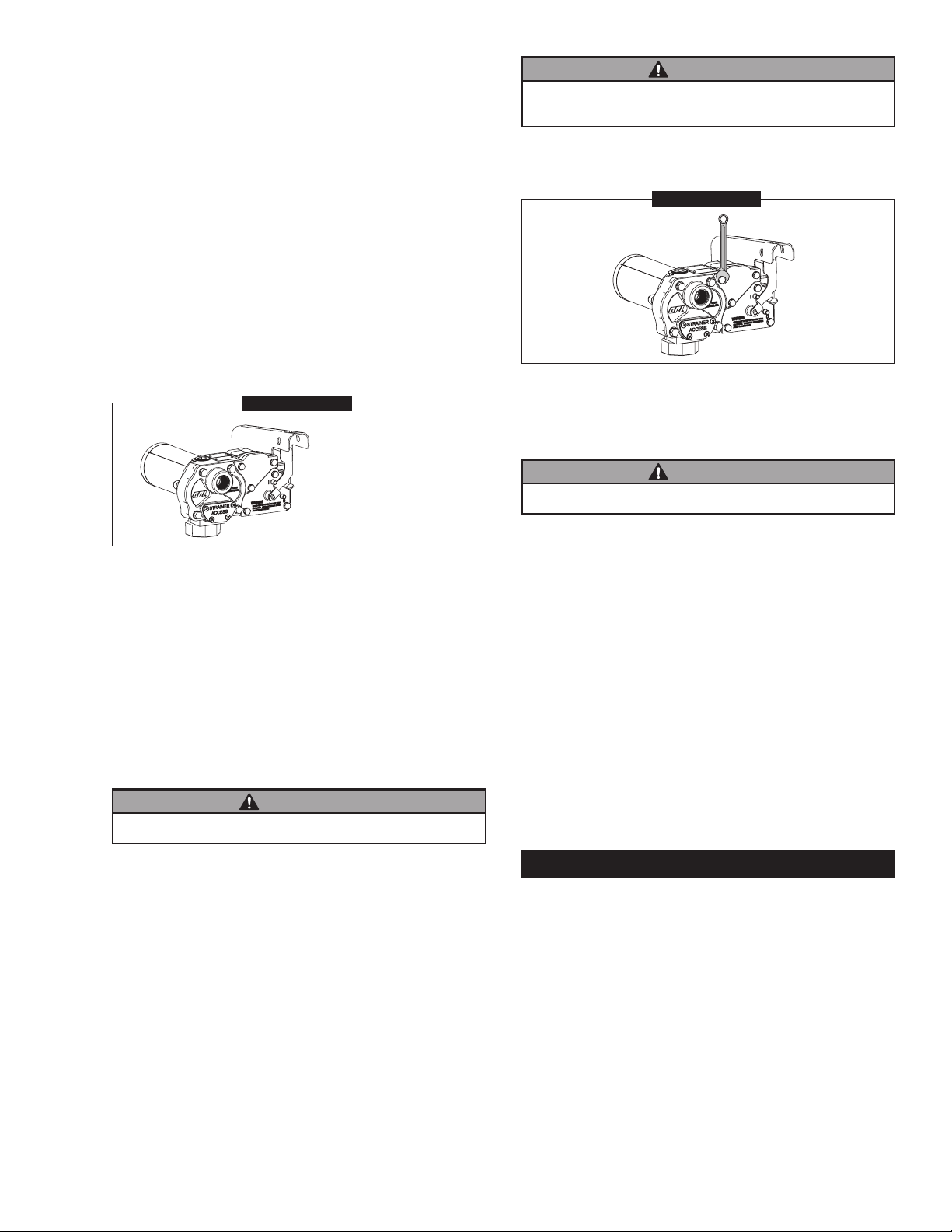
If you require a greater initial prime height, coat the
gears with uid by removing the plug on the top of the
pump and pour a small quantity of motor oil into the gear
cavity. Replace the plug and try again. A foot valve with
pressure relief may be needed to maintain prime.
GENERAL INFORMATION
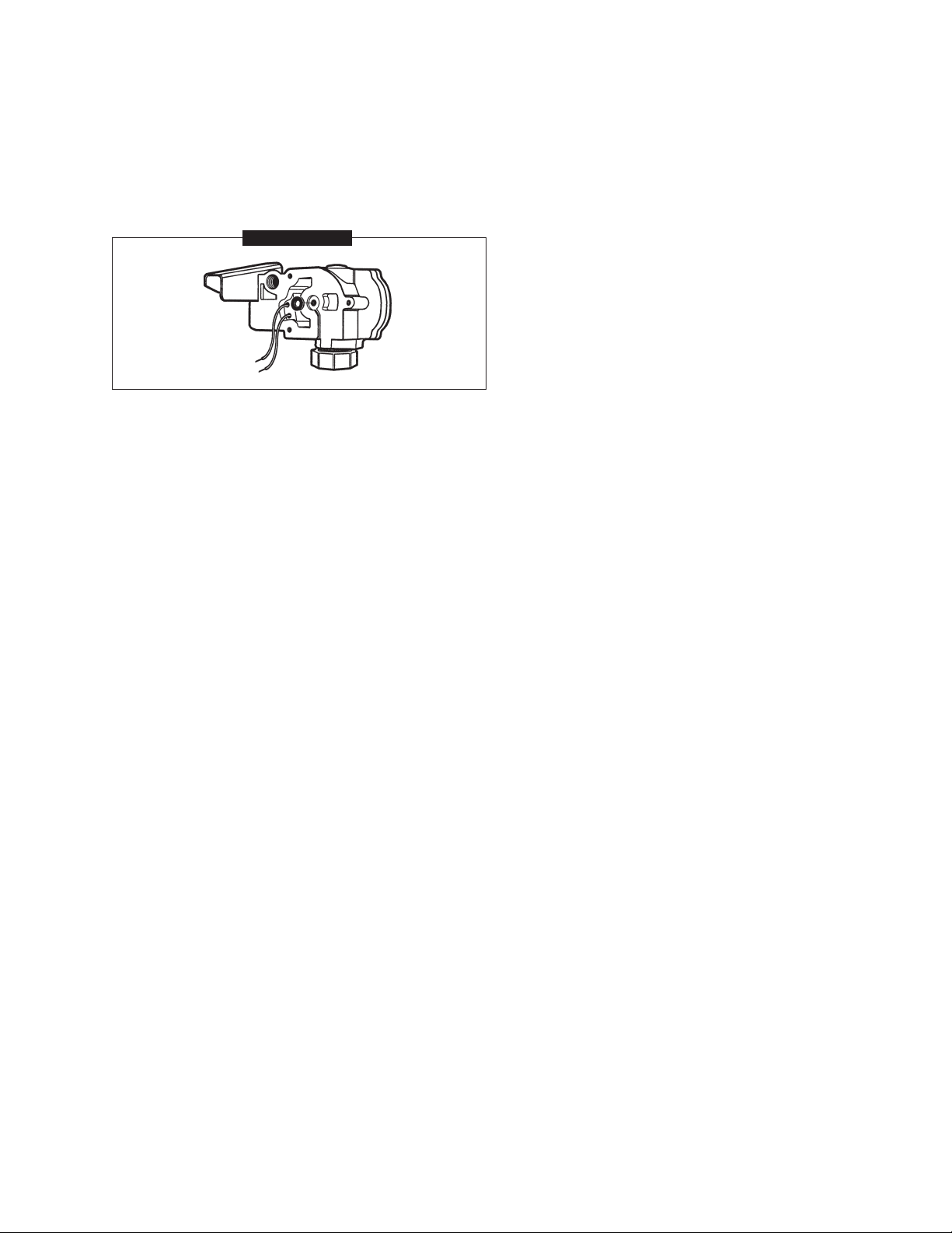
The purpose of this manual is to assist you in install-
ing, operating and maintaining your GPI pump. This
manual covers the 120-voltAC electric gear pump, model
M-1115S-Methanol.
The pump should be connected to a 120-volt AC power
source.
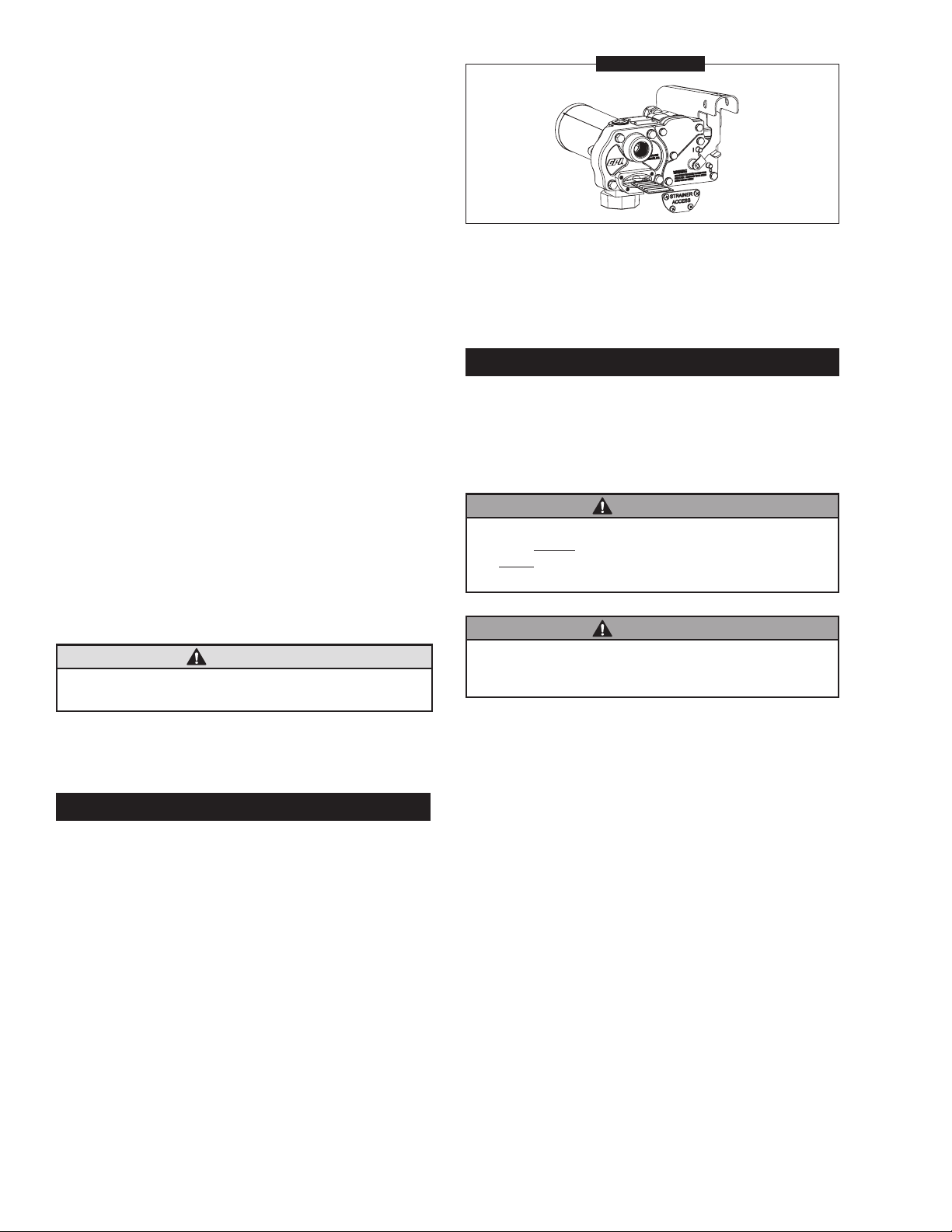
An automatic bypass valve prevents pressure build
up when the pump is on with the nozzle closed. To
avoid damage, do not run the pump more than 10
minutes with the nozzle closed.
The duty cycle of this pump is 30 minutes ON and 30
minutes OFF. Allow the pump to cool for 30 minutes.
This pump is specically designed for use with methanol
and ethanol. The pump is also compatible with gasoline,
diesel fuel (up to 20% biodiesel blends such as B20) and
kerosene. Do not use this pump for dispensing any uids
other than those for which it was designed. To do so may
damage pump components and will void the warranty.
The pump is designed to operate with the appropriate
AC voltage at the motor leads and the ratings are de-
termined at this voltage.
Do not leave the system running with uids. “Dry running”
can damage the pump.
Do not pump the tank completely dry, as contaminants
from the bottom of the tank may enter the pump.
SAFETY INSTRUCTIONS
The following safety alert symbols are used in
this manual. Obey all safety messages that follow
this symbol to avoid possible injury or death.
DANGER DANGER indicates a haz-
ardous situation which, if
not avoided, will result in
death or serious injury.
WARNING WARNING indicates a
hazardous situation which,
if not avoided, could result
in death or serious injury.
CAUTION CAUTION indicates a haz-
ardous situation which, if
not avoided, may result in
minor or moderate injury.
It is your responsibility to:
• know and follow applicable national, state, and local
safety codes pertaining to installing and operating
electrical equipment for use with ammable liquids.