manuals.online logo
Brands
  1. Home
  2. •
  3. Brands
  4. •
  5. GPI
  6. •
  7. Water Pump
  8. •
  9. GPI Dual-Flo HP-100C User manual

GPI Dual-Flo HP-100C User manual

The GPI HP-100C Dual-Flo
®
Piston Hand Pump is designed to
manually pump herbicides and chemical products compatible
with aluminum, fluoroelastmer and EPDM. The user has the
flexibility of operating the pump at two flowrates. A setting of
1/2-gallon provides faster high-capacity flow. A 1/4-gallon set-
ting allows for easier pumping of fluids.
Read Me!
Observe standard precautions when handling herbicides and
chemical products. Fluids to be pumped must be compatible
with pump component materials.
Damage Inspection
Upon receipt of your pump system, carefully inspect visible
components for any damage that may have occurred during
shipping. Note that the pump includes a suction pipe, dis-
charge hose, and nozzle. If any parts are damaged or missing,
please contact your distributor.
GENERAL INFORMATION
HP-100C Dual-Flo
®
Piston Hand Pump
Owner’s Manual
Use the following procedures to install the HP-100C Piston
Hand Pump on a tank with a 2-inch bung.
Install Suction Pipe
1. Remove the two protective plugs from the pump inlet and
outlet ports.
2. Wrap the threaded end of the suction pipe with 3 to 4 turns
of Teflon
®
tape.
3. Insert the suction screen into the inlet cover.
4. Place the spacer in the inlet cover to secure the inlet screen.
5. Install the suction pipe into the inlet cover and tighten firmly
with a pipe wrench.
Install Pump on Tank
1. Before installing the pump, clean the tank interior of all dirt
and foreign material.
2. Lubricate the threads of the inlet cover with Teflon
®
tape or
a thread-sealing compound approved for use with herbi-
cides and chemical products.
3. Extend the adjustable suction pipe to its full length and
carefully insert it into tank opening. The suction pipe will
adjust to the length needed and rest on the bottom of tank.
INSTALLATION
5252 East 36th Street North
Wichita, KS USA 67220-3205
TEL: 316-686-7361
FAX: 316-686-6746
“A Great Plains Ventures Subsidiary”
www.gpi.net
1-800-835-0113
Rev. A 921334-05
02/05
Figure 1
NOTE: The suction pipe supplied has a variable length of 22 to
40 inches. If additional length is needed, order the 15-inch
Suction Pipe Extension Kit.
4. Thread the inlet fitting of the pump onto the tank and turn the
pump to tighten snugly.
NOTE: To prevent the buildup of pressure and possible herbi-
cide or chemical leakage through the nozzle, make sure the
tank is vented.
Install Hose and Nozzle Assembly
Apply 3 to 4 wraps of Teflon
®
tape to the threaded end of the
hose and hand-tighten into the outlet cover until snug.
Install Handle
The HP-100C Piston Hand Pump gives the operator a choice of
two flow settings:
•1/4 gallon setting has low resistance and pumps 1/4 gallon
per stroke cycle.
•1/2 gallon setting has higher resistance and pumps 1/2
gallon per stroke cycle.
Volume per stroke is determined by connecting the piston shaft
to the appropriate handle setting as outlined below. Clevis pins
may be installed from either side of handle.
1. Slide the handle grip onto the pump handle.
2. To install the links on the pump, insert a long clevis pin
through the link ends and the pump’s link holes. Secure with
a small cotter pin. (Figure 1)
3. Attach the free ends of the links to the bottom, outer
surfaces of the handle. Insert a long clevis pin through the
holesonbothlinksandthelowestholeonthehandle.Secure
with a small cotter pin. (Figure 2)
4. Insert a screwdriver in the piston shaft of the pump and pull
the piston out. Install the shaft on the handle at either piston
hole by placing a short clevis pin through the handle and the
piston shaft end and securing with the hitch clip pin.
NOTE: Select the upper piston hole on the handle for the 1/2-
gallon setting (Figure 3) or the lower piston hole for the 1/4-
gallon setting. Flow settings can be changed at any time by
repositioning the piston shaft on the handle.
NOTE: Lock the handle to the pump by pushing the handle
against the pump and inserting a padlock through either of
thetop holes in the handle and through the pump’s lock hole.
(Figure 4)
To Dispense Fluid
1. Remove the nozzle from its holder and insert into the
container.
2. Choose a handle setting for the desired flowrate:
–1/4-gal. setting for low-volume, low-resistance pumping
–1/2-gal.settingforhigh-volume,high-resistancepumping
3. To operate pump, manually move the handle in a push/pull
motion. (Figure 5)
4. After dispensing the desired amount of fluid, drain the hose
and nozzle. Place the nozzle in its holder and return the
handle to its upright storage position.
During daily use, the GPI HP-100C Piston Hand Pump is
essentially maintenance free. However, the pump should be
inspected periodically for signs of leakage. If leaks are present,
make appropriate repairs. Refer to the Troubleshooting sec-
tion.
Proper cleaning is essential to the service life of any product
used with herbicides or chemicals. Use clean water or cleaning
agent recommended by the chemical manufacturer to flush the
pump thoroughly after each use. Make sure the cleaning agent
is compatible with Aluminum, Fluoroelastmer and EPDM. Do
not allow deposits to dry, this can cause pump damage.
OPERATION & MAINTENANCE
Proper care and operation are essential for the safe
transfer of chemical products. Goggles, appropriate
protective gloves and any other protection, as recom-
mended by the chemical manufacturer for handling
herbicidesorchemical,shouldbe observedwhentrans-
ferring these fluids or servicing the pump.
! ! ! C A U T I O N ! ! !
Figure 2
Attach links to first hole
Use for 1/2 gallon setting
Use for 1/4 gallon setting
➤➤
➤➤
➤➤
SYMPTOM PROBABLE CAUSE CORRECTIVE ACTION
A. FLUID LEAKS AROUND 1. Packing seals settled Tighten two screws on the retainer and torque to approximately 20 lb. in. (or hand tighten then another
SHAFT SEAL half turn until leak stops)
2. Seals worn Remove the two screws on the retainer and remove the retainer and bearing. Remove all three seals
and replace.
B. FLUID LEAKS AT 1. Anti-siphon valve or Replace vent plug assembly. Remove the black cap. Remove old vent plug assembly by turning
ANTI-SIPHON VALVE O-ring damaged counterclockwise. Install new vent plug assembly. Replace cap.
C. LOW FLOWRATE 1. Inlet screen clogged Remove the pump from the tank. Remove the suction pipe, spacer, and inlet screen from the bottom of
the pump. Clean the inlet screen and assemble. Place the pump on the tank using installation instructions.
2. Suction pipe leak Remove the pump from the tank. Inspect the spacer and suction pipe to ensure they are not worn or
damaged. Replace as necessary and install the suction pipe and pump again using installation instructions.
3. Piston ring or liner worn Remove the piston cover and inspect the piston ring and liner. Scoring and severe scuffing on the liner
indicates wear. If necessary, install an Overhaul Kit.
4. Piston cracked Remove the piston cover and inspect the piston. Install an Overhaul Kit, if necessary.
D. PUMP SEIZED 1. Debris in piston or liner Disassemble and clean the piston and liner. Check for debris lodged in the piston ring or behind the liner.
Small dimples in the liner indicate dirt, debris or welding slag contaminants in the tank. Replace the piston
ring and liner. If appropriate, flush the tank of all contaminants.
TROUBLESHOOTING
Figure 3
1/2 gallon setting
shown here
➤➤
Figure 4
A
A
A
ILLUSTRATED PARTS DRAWING
Kits and Accessories
114510-2 Hardware Kit includes handle grip, links, pins, and screen.
114506-2 Overhaul Kit includes piston ring, three seals, packing seals,
and liner.
114509-1 Inlet Cover Kit includes inlet cover, spacer, and screen.
115527-2 Suction Pipe Extension, 15 inches.
A
B
C
Item No.n
No. Part No. Description Req’d.
114510-2 Hardware Kit ( ) ............ 1
2 114014-2 Handle ............................... 1
8 904004-30 Screw, Hex Head,
10-32 x 5/8 in. ..............2
9 114017-2 Retainer ............................. 1
10 114016-1 Bearing ..............................1
13 114034-1 Packing Seal or (Kit ) .... 3
14 114042-1 Body .................................. 1
15 114009-1 Spring................................4
16 114007-1 Plate ..................................2
17 114008-1 Valve .................................4
18 114500-5 Outlet Cover, 3/4 in. .......... 1
19 904002-23 Screw, Sems,
1/4-20 x 3/4 in. ........... 14
20 114027-1 Seal or (Kit ) .................. 2
21 123028-1 Vent Plug Assembly .......... 1
906003-4 Cap ...................................1
23 114041-1 Piston Cover ..................... 1
24 901001-79 Cover Seal or (Kit ) .......1
25 906005-58 Piston Ring or (Kit ) ...... 1
26 114021-1 Piston Assembly ............... 1
27 114011-1 Liner or (Kit ) ................. 1
32 114509-1 Inlet Cover Kit ( ) .......... 1
34 114037-1 Inlet Screen or (Kit ) ..... 1
35 114038-1 Spacer or (Kit ) ............. 1
36 110100-1 Adjustable Suction Pipe,
22-40 in. .......................1
37 114504-4 Hose & Nozzle Assy Kit .... 1
B
AA
CC
C
B
B
B
B
The HP-100C DUAL-FLO
®
Piston Hand Pump is compatible
with a wide variety of herbicide and chemical products and fits
any container with a 2-inch NPT bung.
Construction Lightweight, die-cast aluminum hous-
ing. Stainless steel piston shaft and
liner. Fluoroelastomer seals. Built-in air
valve to prevent leakage at the nozzle.
Pumping Capacity 1/2 gallon (1.9 litres) per stroke cycle.
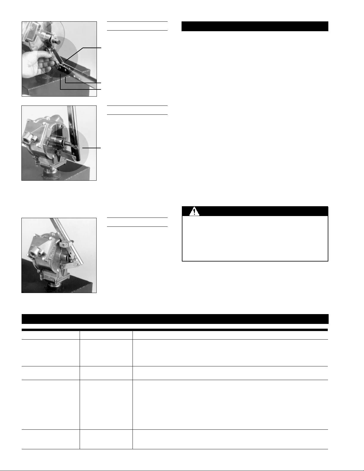
Pumping Settings 1/2 gallon setting for high volume, high
resistance.
1/4 gallon setting for low volume, low
resistance.
Inlet Standard 1-inch NPT pipe.
Outlet Standard 3/4-inch NPT pipe.
Shipping Weight 14 lbs.
Hose and Nozzle 3/4 inch x 8 foot EPDM hose. Thermo-
plastic unleaded nozzle. Built-in nozzle
holder.
Suction Pipe Plastic, adjustable 22 to 40 inches.
For warranty consideration, parts or other service information,
please contact your local distributor or the GPI Customer
Service Department in Wichita, Kansas, during normal busi-
ness hours.
1-800-835-0113
To obtain prompt, efficient service, be prepared with the
following information:
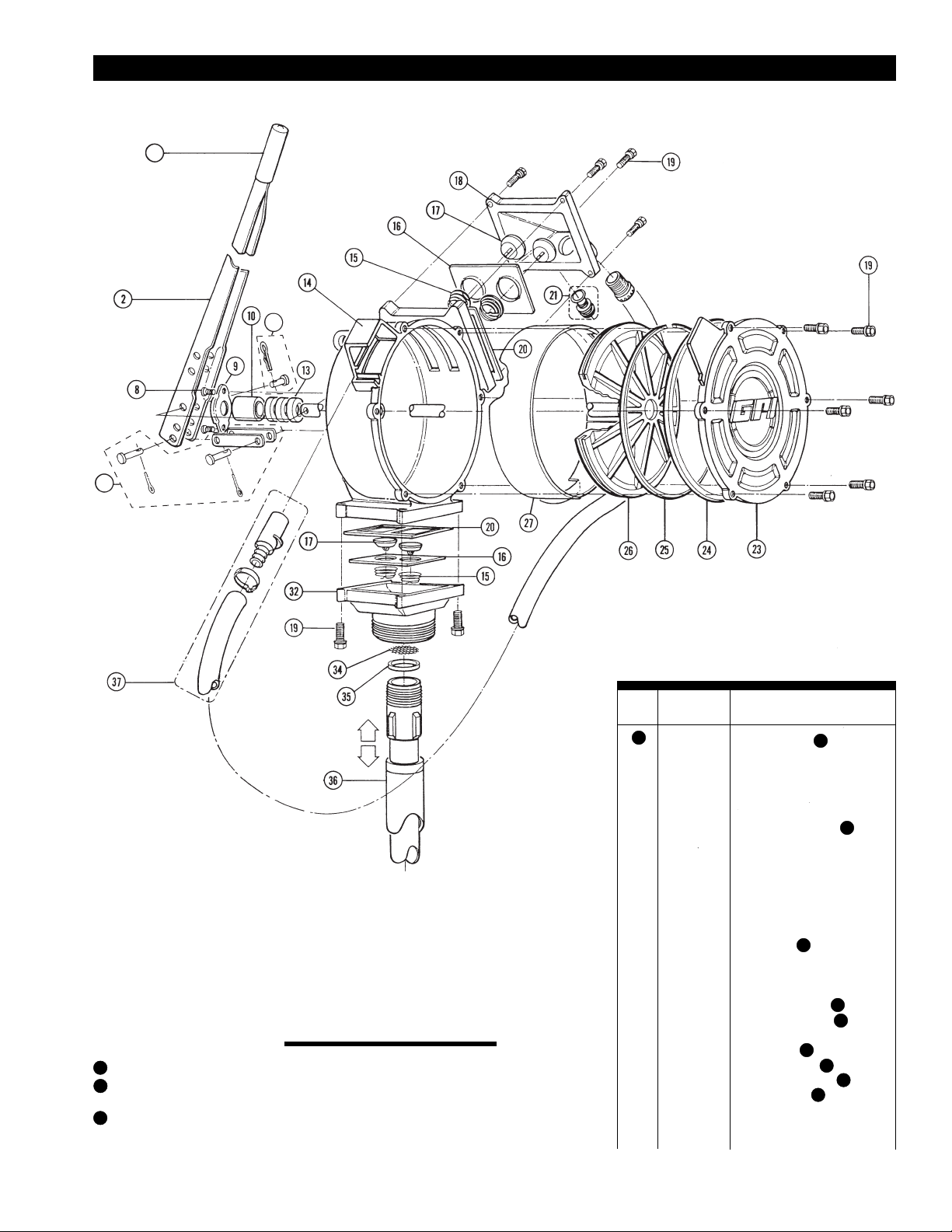
•The model number of your pump.
•The manufacturing date of your pump.
•Part descriptions and numbers.
Part descriptions and numbers can be obtained from the
Illustrated Parts Drawing.
For warranty service, be prepared with your original sales slip
or other evidence of purchase date.
Please contact GPI before returning any pump. It may be
possible to diagnose the trouble and find a solution with a
telephone call. GPI can also inform you of any special require-
ments you will need to follow for shipping.
SPECIFICATIONS PARTS AND SERVICE
Do not return the pump without authority from the
Customer Service Department. Due to strict govern-
ment regulations, GPI cannot accept pump unless they
have been drained and cleaned.
! ! ! WARNING ! ! !
Limited Warranty Policy
Great Plains Industries, Inc. 5252 E. 36
th
Street North, Wichita, KS USA 67220-3205,
hereby provides a limited warranty against defects in material and workmanship on
all products manufactured by Great Plains Industries, Inc. This product includes a
1 year warranty. Manufacturer’s sole obligation under the foregoing warranties will
be limited to either, at Manufacturer’s option, replacing or repairing defective Goods
(subject to limitations hereinafter provided) or refunding the purchase price for such
Goods theretofore paid by the Buyer, and Buyer’s exclusive remedy for breach of any
such warranties will be enforcement of such obligations of Manufacturer. The
warranty shall extend to the purchaser of this product and to any person to whom
such product is transferred during the warranty period.
Thewarrantyperiodshallbeginon the date ofmanufacture or on thedate of purchase
with an original sales receipt. This warranty shall not apply if:
A. the product has been altered or modified outside the warrantor’s duly
appointed representative;
B. the product has been subjected to neglect, misuse, abuse or damage or
has been installed or operated other than in accordance with the
manufacturer’s operating instructions.
To make a claim against this warranty, contact the GPI Customer Service Depart-
ment at 316-686-7361 or 800-835-0113. Or by mail at:
Great Plains Industries, Inc.
5252 E. 36
th
St. North
Wichita, KS, USA 67220-3205
The company shall, notify the customer to either send the product, transportation
prepaid, to the company at its office in Wichita, Kansas, or to a duly authorized
service center. The company shall perform all obligations imposed on it by the terms
of this warranty within 60 days of receipt of the defective product.
GREAT PLAINS INDUSTRIES, INC., EXCLUDES LIABILITY UNDER THIS WAR-
RANTY FOR DIRECT, INDIRECT, INCIDENTAL AND CONSEQUENTIAL DAMAGES
INCURRED IN THE USE OR LOSS OF USE OF THE PRODUCT WARRANTED
HEREUNDER.
Thecompany herewith expressly disclaimsany warranty of merchantabilityor fitness
for any particular purpose other than for which it was designed.
This warranty gives you specific rights and you may also have other rights which vary
from U.S. state to U.S. state.
Note: In compliance with MAGNUSON MOSS CONSUMER WARRANTY ACT – Part
702 (governs the resale availability of the warranty terms).
Dual-Flo and GPI are registered trademarks of
Great Plains Industries, Inc.
© 2005 by GREAT PLAINS INDUSTRIES, INC., Wichita, KS
Printed in U.S.A. 02/05
5252 East 36th Street North
Wichita, KS USA 67220-3205
TEL: 316-686-7361
FAX: 316-686-6746
“A Great Plains Ventures Subsidiary”
www.gpi.net
1-800-835-0113
Rev. A 921334-05

Other GPI Water Pump manuals

GPI PA-200 User manual

GPI

GPI PA-200 User manual

GPI G20-012PX User manual

GPI

GPI G20-012PX User manual

GPI M-180S User manual

GPI

GPI M-180S User manual

GPI EZ-8 User manual

GPI

GPI EZ-8 User manual

GPI M-3295 Series User manual

GPI

GPI M-3295 Series User manual

GPI PA-120H User manual

GPI

GPI PA-120H User manual

GPI HP-90 User manual

GPI

GPI HP-90 User manual

GPI EZ-8RV User manual

GPI

GPI EZ-8RV User manual

GPI GPRO V20 User manual

GPI

GPI GPRO V20 User manual

GPI M-1115S User manual

GPI

GPI M-1115S User manual

GPI M-150S-EM User manual

GPI

GPI M-150S-EM User manual

GPI PA-120DEF User manual

GPI

GPI PA-120DEF User manual

GPI M-1115S-AU User manual

GPI

GPI M-1115S-AU User manual

GPI M-150S User manual

GPI

GPI M-150S User manual

GPI EZ-8-Methanol User manual

GPI

GPI EZ-8-Methanol User manual

GPI M-3130-AV User manual

GPI

GPI M-3130-AV User manual

GPI RP-10 User manual

GPI

GPI RP-10 User manual

GPI G8 User manual

GPI

GPI G8 User manual

GPI M-150S-EM User manual

GPI

GPI M-150S-EM User manual

GPI L 5016 User manual

GPI

GPI L 5016 User manual

GPI G20-012PO User manual

GPI

GPI G20-012PO User manual

Popular Water Pump manuals by other brands

DAB FEKABOX 200 Instructions for installation

DAB

DAB FEKABOX 200 Instructions for installation

Tuson RIN72539 user guide

Tuson

Tuson RIN72539 user guide

Bosch Rexroth 32 Series Repair instructions

Bosch

Bosch Rexroth 32 Series Repair instructions

Grundfos DMH 251 Installation and operating instructions

Grundfos

Grundfos DMH 251 Installation and operating instructions

Graco G3 Max Series instruction manual

Graco

Graco G3 Max Series instruction manual

Stuart Turner PH 45 ES Installation, operation & maintenance instructions

Stuart Turner

Stuart Turner PH 45 ES Installation, operation & maintenance instructions

GE UPK3 installation instructions

GE

GE UPK3 installation instructions

SKF LINCOLN 1886 Series Original instructions

SKF

SKF LINCOLN 1886 Series Original instructions

CountyLine CL30210 owner's manual

CountyLine

CountyLine CL30210 owner's manual

EM SRP 15502 DR Basic line operating instructions

EM

EM SRP 15502 DR Basic line operating instructions

MagnaTex MP Series Installation, operation and maintenance manual

MagnaTex

MagnaTex MP Series Installation, operation and maintenance manual

Hallmark MA0345X-9 manual

Hallmark

Hallmark MA0345X-9 manual

VARO POWERplus Water POW67904 manual

VARO

VARO POWERplus Water POW67904 manual

vacuubrand MV 10C VARIO select Instructions for use

vacuubrand

vacuubrand MV 10C VARIO select Instructions for use

Pentair FP5112 Installation & operation manual

Pentair

Pentair FP5112 Installation & operation manual

vacuumbrand PC 510 select Instructions for use

vacuumbrand

vacuumbrand PC 510 select Instructions for use

Pontec PondoDrain Mud 8000 operating instructions

Pontec

Pontec PondoDrain Mud 8000 operating instructions

Graco President 224 757 instructions

Graco

Graco President 224 757 instructions

manuals.online logo
manuals.online logoBrands
  • About & Mission
  • Contact us
  • Privacy Policy
  • Terms and Conditions

Copyright 2025 Manuals.Online. All Rights Reserved.