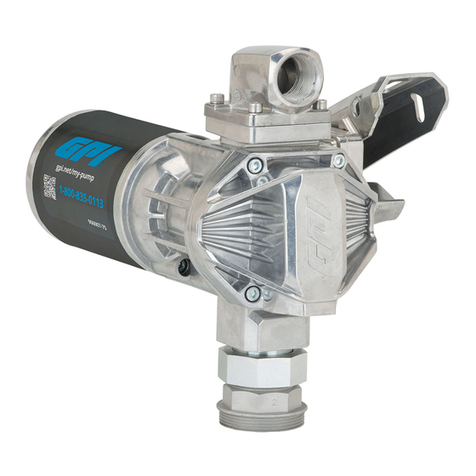
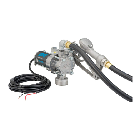
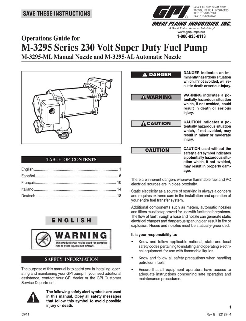
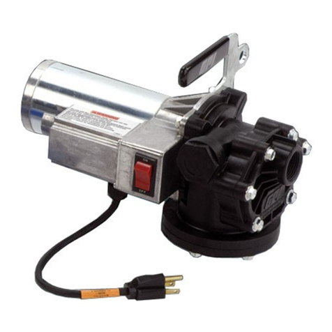
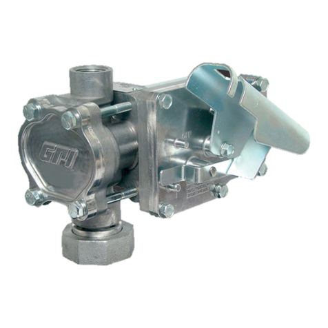
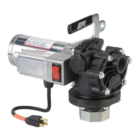
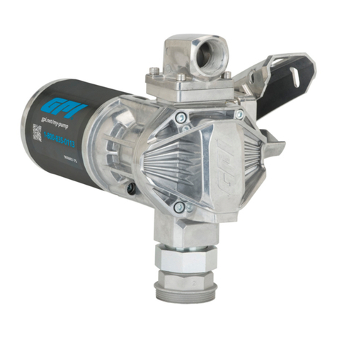
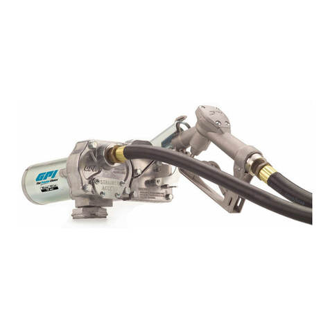
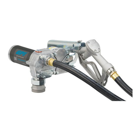
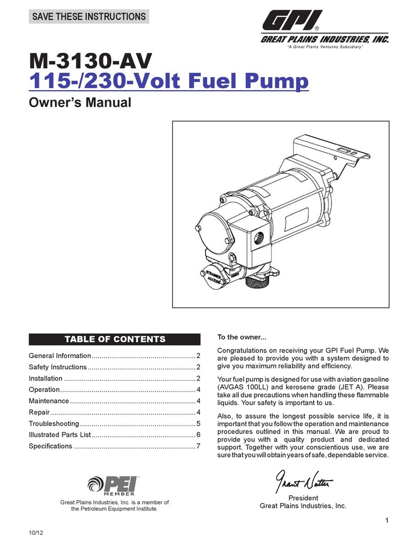
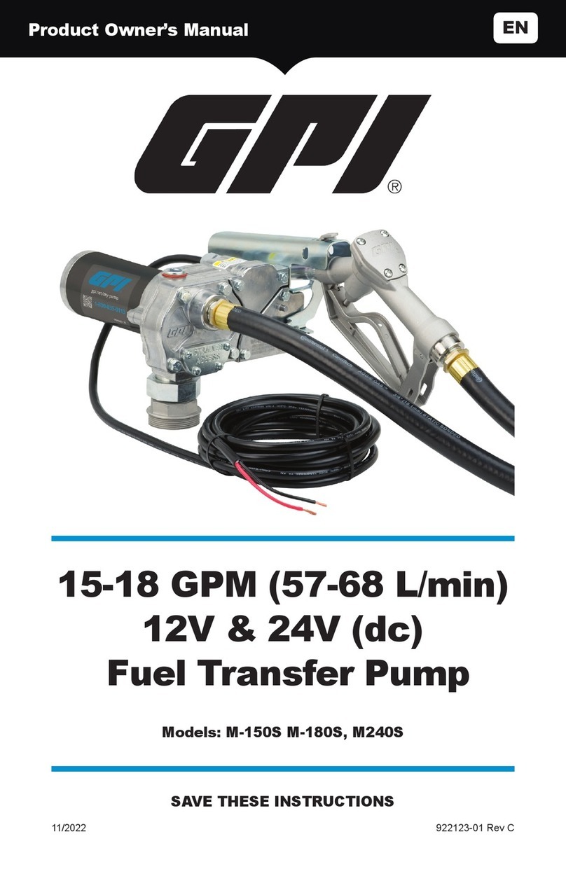
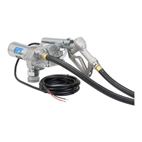
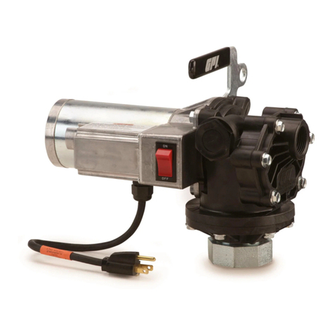
GPI GPRO V20 User manual

922146-01 Rev -
08/23
Product Owner’s Manual
Manual del propietario del producto
Manuel du propriétaire du produit
V20
115V & 230V (AC)
Fuel Transfer Pump
Bomba de transferencia de combustible
Pompe de transfert de carburant
20 GPM (76 L/min)
Models: V20-115PO, V20-230PX, V20-115MD, V20-230MD,
V20-115MU, V20-230MU, V20-115AD, V20-230AD, V20-
115AU, V20-230AU, V20-115RD, V20-230RD
(PATENT-PENDING)

EN
ES
FR
Thank you for choosing Great Plains Industries as your preferred brand! Our
team places innovation, precision, and care into every product made, providing
you with the best total value. This manual contains critical product information.
Save these instructions and observe all safety information to prevent personal injury or property
damage. See back cover for warranty and customer support details.
DO NOT RETURN THIS PRODUCT TO THE STORE!
Please contact Great Plains Industries, Inc. before returning any product. If you are missing parts,
or experience problems with your installation, contact our Customer Support Department. We will
be happy to assist you.
SAVE / GUARDAR / CONSERVEZ
Model / Modelo / Modèle #: �������������������
Serial / Serie / Série #: ������������������������
Date / Fecha / Date:��������������������������
Call / Llamar / Appel: 800-835-0113 or 316-686-7361
Email: [email protected]
Website: gpi.net
¡Gracias por elegir Great Plains Industries como su marca preferida! Nuestro
equipo pone innovación, precisión y cuidado en cada producto fabricado,
proporcionándole el mejor valor total. Este manual contiene información crítica
del producto. Guarde estas instrucciones y observe toda la información de seguridad para evitar
lesiones personales o daños materiales. Consulte la contraportada para obtener detalles sobre la
garantía y el soporte al cliente.
¡NO DEVUELVA ESTE PRODUCTO A LA TIENDA!
Comuníquese con Great Plains Industries, Inc. antes de devolver cualquier producto. Si le faltan
piezas o experimenta problemas con su instalación, comuníquese con nuestro Departamento de
atención al cliente. Estaremos encantados de ayudarle.
Merci d’avoir choisi Great Plains Industries comme votre marque préférée!
Notre équipe place l’innovation, la précision et le soin dans chaque produit
fabriqué, vous offrant la meilleure valeur totale. Ce manuel contient des
informations critiques sur le produit. Conservez ces instructions et respectez toutes
les informations de sécurité pour éviter les blessures corporelles ou les dommages matériels.
Consultez la couverture arrière pour obtenir des détails sur la garantie et le support client.
NE PAS RENVOYER CE PRODUIT AU MAGASIN !
Veuillez contacter Great Plains Industries, Inc. avant de retourner un produit. S’il vous manque
des pièces ou si vous rencontrez des problèmes avec votre installation, contactez notre service
d’assistance à la clientèle. Nous serons heureux de vous aider.

3
SAFETY /
SPECIFICATIONS
ASSEMBLY /
INSTALLATION OPERATION MAINTENANCE
EN
GETTING STARTED
tools.eps
box.eps
magnify_2.eps
warning symbol.eps
measure.eps
plug.eps
oil.eps
megaphone.eps
biohaz.eps
Battery_Caution1.eps
Caution.eps
Crush_Caution1.eps
Electrical_Caution.eps
Face_protection.eps
Fall_Hazard.eps
Fall_protection.eps
GearHand_Hazard.eps
Head_protection.eps
Heavy_Hazard.eps
Hot_surface.eps
Recycle.eps
Resp_protection1.eps
Resp_protection2.eps
Temp_Caution1.eps
body_protection.eps
chemical_Caution.eps
ear_protection1.eps
explosive_caution.eps
eye_protection1.eps
foot_protection.eps
hand_protection.eps
Power Source Requirements
• Pump models that include “115” are to be connected to 115V (ac); Do not
attempt connection of any of these pumps to a (dc) power source. Do not
attempt connection of any of these pumps to a 230V (ac) power source
without reconguring the wiring in the junction box. (see pg.15)
• Pump models that include “230” are to be connected to 230V (ac); Do not
attempt connection of any of these pumps to a (dc) power source. Do not
attempt connection of any of these pumps to a 115V (ac) power source
without reconguring the wiring in the junction box. (see pg.15)
Tools Needed
• Adjustable Wrench, Pipe Wrench, Pliers, Utility Knife, Wire Crimper/Stripper,
and Metric Hex Wrenches (Hex Key).
Model Lockable
Nozzle
Holder
Modular
Fitting &
Hardware
18 FT
Dispensing
Hose Nozzle
PO/PX X X N/A N/A
RD N/A X N/A N/A
MD X X 1” Manual Diesel
MU X X 3/4” Manual Unleaded
AD X X 1” Automatic Diesel
AU X X 3/4” Automatic Unleaded
CONTENTS
BEFORE YOU BEGIN
Fuel Compatibility Statement
• This fuel pump is designed, tested and approved for use with gasoline
blends (up to E15), diesel fuel blends (up to B20) and kerosene. In addition,
the PO/PX models are approved for use with Aviation Gasoline (AVGAS
100LL) and kerosene (Jet A). Please take all due precautions when
handling these ammable liquids.
• Do not use this pump for dispensing any uids other than those for which it
was designed. To do so may damage the pumps components and will void
the warranty.
UNPACKING
Shipping Damage Check
• After unpacking the unit, inspect carefully for any damage that may have
occurred during transit. Check for loose, missing or damaged parts.
Shipping damage claims must be led with carrier. Review General Safety
Instructions and all Caution, Warning, and Danger statements as shown.
tools.eps
box.eps
magnify_2.eps
warning symbol.eps
measure.eps
plug.eps
oil.eps
megaphone.eps
biohaz.eps
Battery_Caution1.eps
Caution.eps
Crush_Caution1.eps
Electrical_Caution.eps
Face_protection.eps
Fall_Hazard.eps
Fall_protection.eps
GearHand_Hazard.eps
Head_protection.eps
Heavy_Hazard.eps
Hot_surface.eps
Recycle.eps
Resp_protection1.eps
Resp_protection2.eps
Temp_Caution1.eps
body_protection.eps
chemical_Caution.eps
ear_protection1.eps
explosive_caution.eps
eye_protection1.eps
foot_protection.eps
hand_protection.eps
Attention: Biodiesel blends have not yet been evaluated by any regulating agency
tools.eps
box.eps
magnify_2.eps
warning symbol.eps
measure.eps
plug.eps
oil.eps
megaphone.eps
biohaz.eps
Battery_Caution1.eps
Caution.eps
Crush_Caution1.eps
Electrical_Caution.eps
Face_protection.eps
Fall_Hazard.eps
Fall_protection.eps
GearHand_Hazard.eps
Head_protection.eps
Heavy_Hazard.eps
Hot_surface.eps
Recycle.eps
Resp_protection1.eps
Resp_protection2.eps
Temp_Caution1.eps
body_protection.eps
chemical_Caution.eps
ear_protection1.eps
explosive_caution.eps
eye_protection1.eps
foot_protection.eps
hand_protection.eps

MAINTENANCE OPERATION ASSEMBLY /
INSTALLATION GETTING STARTED
4
EN
SAFETY /
SPECIFICATIONS
GENERAL SAFETY INSTRUCTIONS
IMPORTANT: It is your responsibility to:
• Know and follow applicable national, state and local safety codes pertaining
to installing and operating electrical equipment for use with flammable
liquids.
• Know and follow all safety precautions when handling petroleum fuels.
• Ensure that all equipment operators have access to adequate instructions
concerning safe operating and maintenance procedures.
Observe all safety precautions concerning safe handling of petroleum fuels
SYMBOLS
Description of imminent hazard and failure to avoid hazard will
result in death.
Description of hazard and possible resulting injures or death.
Description of hazard and possible resulting injuries.
This symbol indicates a general warning to the user. See
additional specific warnings.
This symbol indicates electrical shock hazard. Follow proper
installation and maintenance instructions in this manual.
This symbol indicates hot surface. Take care to avoid coming
into contact with hot surface.
This symbol indicates automatic restart. Pump contains
thermal protection which automatically shuts off motor before
overheating. Pump will turn back on automatically after cooling.
Turn switch OFF and wait 30 minutes to resume normal
pumping. Disconnect power before any inspection or service.
Owner’s manual must be read before using, inspecting, or
servicing this product.
Disconnect power when product is unattended or in the case
of a malfunction. Disconnect power before any inspection,
servicing, or maintenance.
To prevent physical injury or property damage, observe
precautions against fire or explosion when dispensing fuel. Do
not operate the system in the pressence of ignition sources
such as, but not limited to: open flames, lighted cigarettes,
running or hot engines, gas or electric heaters.
gpi.net/my-pump
SEE OWNER’S MANUAL FOR DETAILS
VOIR LE MANUEL DU PROPRIÉTAIRE
POUR PLUS DE DÉTAILS
VEA EL MANUAL DEL
PROPIETARIO PARA DETALLES
VEJA O MANUAL DO
PROPRIETÁRIO PARA DETALHES
922144-02

5
GETTING STARTED ASSEMBLY /
INSTALLATION OPERATION MAINTENANCE
EN
SAFETY /
SPECIFICATIONS
GENERAL SAFETY INSTRUCTIONS (CONTINUED)
SAFETY WARNINGS
To prevent physical injury or property damage, observe
precautions against fire or explosion when dispensing fuel. Do
not operate the system in the presence of any source of ignition
including running or hot engines, lighted tobacco products, gas
or electric heaters, or any type of electronic device. A spark can
ignite fuel vapors.
Observe precautions against electrical shock when operating
the system. Serious or fatal shock can result from operating
electrical equipment in damp or wet locations.
Observe precautions against electrical shock when servicing
the pump. Always disconnect power before repairing or
servicing. Never apply electrical power to the system when any
of the cover plates are removed.
To ensure safe operation, all fuel transfer systems must be
properly grounded. Proper grounding means a continuous
metal-to-metal contact from one component to the next,
including tank, tank mount, pump, meter, filter, hose and nozzle.
Care should be taken to ensure proper grounding during initial
installation and after any service or repair procedures. For your
safety, please take a moment to review the warnings below.
Inspect external pump wiring regularly to make sure it is
correctly attached to the battery. To avoid electrical shock, use
extra care when connecting the pump to power.
Avoid prolonged skin contact with petroleum fuels. Use
protective goggles, gloves and aprons in case of splashing or
spills. Change saturated clothing and wash skin promptly with
soap and water.
All wetted connections should be sealed with appropriate
sealant, thread tape, O-rings, and securely fastened. Leaking
fuel may cause the potential for fire and explosion.
PUMP MODELS THAT MAY BE USED IN AVIATION REFUELING
(PO/PX MODELS) ARE NOT SUPPLIED WITH APPROPRIATE HOSE, NOZZLE,
AND SUCTION PIPE. THESE ITEMS MUST MEET NFPA 407 GUIDELINES.
For ground-based refueling only. Do not use in or on
the aircraft. For use with aviation gasoline (AVGAS
100LL) and kerosene grade (Jet A). User should consult
NFPA 407 Standard for Aircraft Fuel Servicing for safety
requirements during ground fuel servicing of aircraft using
liquid petroleum fuels. This product has no actual or implied
compliance with this standard.
This pump is provided with an internal auxiliary temperature-
limiting device which automatically shuts off the motor before
overheating. The pump will turn back on automatically after
cooling if the switch is not in the off position. Turn the switch
OFF and wait 30 minutes to resume normal operation.
If using solvent to clean pump components or tank, observe the
solvent manufacturer’s recommendations for safe
use and disposal.

MAINTENANCE OPERATION ASSEMBLY /
INSTALLATION GETTING STARTED
6
EN
SAFETY /
SPECIFICATIONS
PX PO RD MD AD MU AU
Housing Material Cast Iron
Pump Rate* 20 GPM (76 L/min)
Duty Cycle Intermittent, 30 minute ON, 30 minute OFF
Suction Lift* Up to 15 ft. (4.5 m)
Operating
Temperature -20 °F to 125 °F (-29 °C to 52 °C)
XTS Operating
Temperature
Extreme Temperature Series pumps are
capable of operation down to -40 °F (-40 °C).
Any pump operation below -20 °F (-29 °C) has
not been evaluated by any regulating agency.
Max. Surface
Temperature 320 °F (160 °C)
Operating
Pressure Up to 25 PSI (1.72 bar)
Input* 115VAC 60Hz
230VAC 50/60Hz
Current Draw* 115V AC 60Hz 5.5A
230V AC 60Hz 2.8A
Motor* 1690 RPM, 1/2 hp
Whole Pump
Approval UL 79
Motor Approval
cULus
Listed, Class
I Div 1
IECEx/ATEX
Zone 1
cULus Listed, Class I Div 1 Only
Motor Protection Thermal Breaker (Automatically Resets)
Tank Adapter 2” BSPT 2 in. NPT
Inlet 1” BSPP 1 in. NPT
Outlet 1” BSPP 1 in. NPT
Hose Type N/A Buna-N Electrically Conductive Discharge
Hose with Static Wire
Hose Size N/A 1 in. x 18 ft. (5.5 m) 3/4 in. x 18 ft.
Nozzle N/A
1 in.
Manual
Diesel
1 in.
Auto
Diesel
3/4 in.
Manual
Unleaded
3/4 in.
Auto
Unleaded
*NOTE: 50Hz supply voltage will produce pump rate of 61L/min, suction lift of
3.9m, current draw of 4.3A, motor performance of 1595 RPM, and 4/10 HP.
SPECIFICATIONS

A
B
C
A
B
C
7
GETTING STARTED ASSEMBLY /
INSTALLATION OPERATION MAINTENANCE
EN
SAFETY /
SPECIFICATIONS
Figure 1
DIMENSIONS
A. Pump Assy Width 8.26in. (20.98 cm)
B. Pump Assy Height 11.68 in. (29.67 cm)
C. Pump Assy Depth 14.08 in. (35.76 cm)
SPECIFICATIONS (CONTINUED)

MAINTENANCE OPERATION ASSEMBLY /
INSTALLATION GETTING STARTED
8
EN
SAFETY /
SPECIFICATIONS
SPECIFICATIONS (CONTINUED)
SAFETY TESTING APPROVALS
The V20 has been tested for compliance to the standards issues by Underwriters
Laboratories. The pump utilizes a motor IM050 (or IM050X for PX pump models)
that has been tested for compliance to the standards issues by Underwriters
Laboratories. In addition to UL, the IM050X is compliant with IECEx, and ATEX.
V20
UL 79 (Tenth Edition) Standard for Power-Operated Pumps for Petroleum
Dispensing Products.
IM050 and IM050X
UL 674 (Edition 5): Electric motors and generators for use in hazardous
(classied) locations.
IM050X
IEC Information
Marking string:
Standards used:
IEC 60079-0 (Edition 7.0): Explosive Atmospheres – Part 0: Equipment -
General requirements.
IEC 60079-1 (Edition 7.0): Explosive Atmospheres – Part 1: Equipment
protected by ameproof enclosures “d”.
IECEx specic conditions of use:
1. Flameproof joints are not intended to be repaired.
2. The special fasteners used as securing bolts for the end bell are made of
Class 12.9 type fasteners. The special fasteners used for electrical cover
plate attachment are made of Class 12.9 type fasteners.
ATEX Information
Marking string:
Mfg.
Date
B
162235-01B
G20-012PX
F
Ex db IIA T4 Gb
IECEx UL 19.0027X
REFER TO MANUAL FOR WIRING INSTRUCTIONS
30 ON / 30 MIN. OFF DUTY
-30ºC<Tamb<+55ºC
98ºC RISE
34 AMPS12 VDC 2000 RPM 0.38 HP
2809
ELECTRIC MOTOR FOR
HAZARDOUS LOCATIONS
CLASS I, GROUP D
5252 E 36TH ST N
WICHITA, KS 67220
OP. TEMP.
CODE T3C
OP. TEMP.
CODE T4
DEMKO 19 ATEX 2113X
II 2 G Ex db IIA T4 Gb
Standards used:
EN IEC 60079-0: 2018
EN 60079-1: 2014
ATEX specic conditions of use:
1. Flameproof joints are not intended to be repaired.
2. The special fasteners used as securing bolts for the end bell are made of
Class 12.9 type fasteners. The special fasteners used for electrical cover
plate attachment are made of Class 10.9 or 12.9 type fasteners.
II 2 G Ex db IIA T4 Gb
UL 23 ATEX 3049X
Ex db IIA T4 Gb
IECEx UL 23.0055X

Page intentionally left blank
Página dejada en blanco intencionalmente
Page volontairement laissée vierge
9

MAINTENANCE OPERATION SAFETY /
SPECIFICATIONS GETTING STARTED
10
EN
ASSEMBLY /
INSTALLATION
Mechanical Connections
NOTE: All threaded fuel connections must be sealed with thread tape or a pipe
thread sealing compound approved for use with petroleum fuels and tightened
securely to prevent leakage.
NOTE: This pump must be mounted on a vented tank.
NOTE: This pump is designed to mount directly to a standard 2 in. male pump
tank mount adapter (included).
Install Tank Adapter and Suction Pipe
NOTE: For Aluminum Tank Installation - To prevent thread galling of aluminum
ttings, always prepare the threads for assembly using an anti-seize compound
such as Loctite® 567™, Hernon®Dripstop® 940 or equivalent.
1. Clean the tank interior of all dirt and foreign material.
2. For the suction pipe, a 1 in. steel pipe cut to length and threaded on one
end may be used. Suction pipe should extend to within 3 inches of tank
bottom.
3. Wrap the threaded end of suction pipe with three or four turns of thread tape
(see Figure 2). Thread the suction pipe into the bottom of the adapter and
hand tighten until snug.
4. Wrap the upper threaded end of the tank adapter with three or four turns
of thread tape and insert suction pipe / tank adapter into threaded tank
opening (see Figure 3). Using a wrench, tighten the adapter snugly into the
fuel tank.
Figure 3Figure 2
Install Pump on Tank
Using pliers, remove the plastic plug from inlet port on bottom of pump, then using a
wrench, tighten the pump onto the adapter.
Install Nozzle Cover
NOTE: DO NOT install nozzle cover until after wiring is completed.
NOTE: RD versions do not include a Nozzle Cover. A bracket can be installed in
its place to permanently keep the switch in the “ON” position so that the pump
can be turned on/o at a remote dispense location (see Page 12).
Using a 4mm Hex wrench, install nozzle cover using (2) M6-1.0 x 14mm BHCS in
lower hole (see Figure 4).
Install Outlet Adapter
1. Remove plastic plug from outlet port of pump.
2. Install #222 O-ring into outlet port. Make sure O-ring is seated properly.
3. Using a 5mm Hex wrench, install the (4) M6-1.0 x 20mm SHCS into the
outlet adapter in desired direction on outlet port (see Figure 4).
1
2
3
4
5
INSTALLATION INSTRUCTIONS
Coverplates protect the operator from moving parts. Never
operate the pump without coverplates in place. Never apply
electric power to the pump without coverplates in place. Always disconnect power
before repairing or servicing
If the pump is to be installed in a Hazardous (Classified) location,
it must be installed by a licensed electrician and conform to
National Fire Protection Association (NFPA) codes 30 and 70. You as the owner, are
responsible for seeing that the installation and operation of your pump complies with
NFPA codes as well as any applicable state and local codes. Rigid conduit must be
used to install wiring. Note that the lead wires are factory-sealed isolating the motor
from the junction box. Failure to follow these wiring instructions may result in death or
serious injury from shock, fire or explosion.
NOTE: The MU, AU, MD, and AD pumps are pre-wired for
installation in Class I, Division 2 locations such as portable
fuel tanks, trailers, etc. Connection to a battery will depend upon the application. If
the pump is to be installed in a Class I, Division I location please contact GPI for the
appropriate product.
Do not attempt to power the pump from vehicle wiring smaller
than 12 (14) (10) gauge, such as the cigarette lighter wire, as thin
wires could overheat and cause a fire.
IMPORTANT: Verify switch is in OFF position, then route the electrical wires
to the source of the vehicle power system. Be sure to support the wires as
necessary and protect them from sharp edges, heat, or anything that could
damage the wires.

11
GETTING STARTED SAFETY /
SPECIFICATIONS OPERATION MAINTENANCE
EN
ASSEMBLY /
INSTALLATION
Figure 4
INSTALLATION INSTRUCTIONS (CONTINUED)
Install Hose and Nozzle
1. Wrap one end of the dispensing hose with three to four turns of thread tape
and thread into outlet port. Tighten securely using an adjustable wrench.
2. Wrap opposite end of hose with three or four turns of thread tape
and thread into nozzle. Tighten securely using an adjustable wrench.
3. Place the nozzle into the nozzle holder on the end of the pump motor
housing. Note that the nozzle cannot be placed in the holder unless
the pump switch is OFF (see Figure 8 and 9).
1
2
3
4
5
INSTALLATION INSTRUCTIONS
Coverplates protect the operator from moving parts. Never
operate the pump without coverplates in place. Never apply
electric power to the pump without coverplates in place. Always disconnect power
before repairing or servicing
If the pump is to be installed in a Hazardous (Classified) location,
it must be installed by a licensed electrician and conform to
National Fire Protection Association (NFPA) codes 30 and 70. You as the owner, are
responsible for seeing that the installation and operation of your pump complies with
NFPA codes as well as any applicable state and local codes. Rigid conduit must be
used to install wiring. Note that the lead wires are factory-sealed isolating the motor
from the junction box. Failure to follow these wiring instructions may result in death or
serious injury from shock, fire or explosion.
NOTE: The MU, AU, MD, and AD pumps are pre-wired for
installation in Class I, Division 2 locations such as portable
fuel tanks, trailers, etc. Connection to a battery will depend upon the application. If
the pump is to be installed in a Class I, Division I location please contact GPI for the
appropriate product.
Do not attempt to power the pump from vehicle wiring smaller
than 12 (14) (10) gauge, such as the cigarette lighter wire, as thin
wires could overheat and cause a fire.
IMPORTANT: Verify switch is in OFF position, then route the electrical wires
to the source of the vehicle power system. Be sure to support the wires as
necessary and protect them from sharp edges, heat, or anything that could
damage the wires.
Outlet Adapter M6-1.0 x 20mm
SHCS
M6-1.0 x 14mm
BHCS
Nozzle Cover
#222 O-ring

MAINTENANCE OPERATION SAFETY /
SPECIFICATIONS GETTING STARTED
12
EN
ASSEMBLY /
INSTALLATION
Figure 5
INSTALLATION INSTRUCTIONS (CONTINUED)
For Zone 1 or 2 (IECEx/ATEX)
Use a suitable Ex db cable gland during Zone 1 or 2 installations. Power cord or
cable (not supplied) should be compliant with Clause No. 10.6.2 of IEC 60079-
14. Conductors used for line voltage must have insulation rated at 105°C or
above.
Remote Dispense and Switch Locking Bracket
Attention: RD pumps are only to be used with UL listed equipment/control
devices. The equipment used must be suitable for the area classication it is
being installed in. The RD remote dispenser pump incorporates an external
switch lever lock that holds the pump switch in the “ON” position. The pump is
typically shut o using a remote dispensing device “ON-OFF” mechanism.
Electrical Connections
Electrical wiring and connections must be made only by a licensed electrician
in accordance with national, state and local electrical codes regarding Class I,
Division 1, Group D locations. This includes but is not limited to the National Fire
Protection Association (NFPA) Code 70, Article 501.15(A)(1). Other codes may
apply.
Thread for the conduit connection at the pump junction box is 1/2 in. FNPT.
A 15-amp or 20-amp breaker is recommended.
Wiring Details
1. Remove electrical cover plate (see Figure 5). Install conduit and cable from
supply power to pump junction box. Wiring must be in accordance with
Class I, Division 1 requirements in the applicable national electrical code.
Note that the lead wires are factory-sealed isolating the motor from the
junction box.

13
GETTING STARTED SAFETY /
SPECIFICATIONS OPERATION MAINTENANCE
EN
ASSEMBLY /
INSTALLATION
INSTALLATION INSTRUCTIONS (CONTINUED)
Figure 6
2. Attach ground wire using the green ground screw located inside the junction
box (see Figure 6). The external bonding connection is only a supplemental
bonding connection where local authorities permit or require such a
connection.
Figure 7
NOTE: An accessory AC control circuit can be used to operate a device such
as a signal light or a solenoid operated valve. The “hot” AC lead should be tied
into the large wire nut inside the junction box (see Figure 7), and the neutral lead
should be tied with the neutral at the switch. Maximum amp draw on the control
circuit should be limited to 1 amp.
Neutral
Wire

WIRING DIAGRAM
171902-01
Rev (-)
WIRING DIAGRAM
171902-02
Rev (-)
BROWNBROWN
MAINTENANCE OPERATION SAFETY /
SPECIFICATIONS GETTING STARTED
14
EN
ASSEMBLY /
INSTALLATION
INSTALLATION INSTRUCTIONS (CONTINUED)
NOTE: The V20 is a dual voltage motor that can be converted between 115VAC
and 230VAC if needed. For the motor to run in 115V conguration, couple the
blue and orange motor leads together with a wire nut and then couple the white
and yellow motor leads together along with the yellow lead from the switch with
another wire nut. For the motor to run in 230V conguration, insulate the blue
motor lead with a small wire nut, couple the orange and white motor lead with a
wire nut and couple the yellow motor lead with the yellow lead from the switch
with another wire nut. Refer to the wiring diagram.
3. Match voltage, connect motor to power supply phases. (see Figures 7a/7b)
4. Position wires inside the junction box and replace electrical cover. Install all
four (4) screws.
NON-PX
PX
Figure 7a
Figure 7b

15
GETTING STARTED SAFETY /
SPECIFICATIONS
ASSEMBLY /
INSTALLATION MAINTENANCE
EN
OPERATION
Dispensing Fuel
Remove the nozzle from holder and insert into receiving tank. Turn the pump on
by pushing the switch lever up. Squeeze the handle to start fuel ow. When done,
release the nozzle handle, turn the pump o, and return the nozzle to its holder.
IMPORTANT: This pump is designed to be self-priming. If fuel is not delivered
within 15 to 20 seconds, turn the pump o and refer to priming information in the
Troubleshooting Guide. (see pg. 17)
OPERATION
IMPORTANT: Always follow safety precautions when operation this equip-
ment. Review the safety instructions.
To prevent physical injury or property damage, observe
precautions against fire or explosion when dispensing fuel. Do
not operate the system in the presence of any source of ignition including running or
hot engines, lighted tobacco products, gas or electric heaters, or any type of electronic
device. A spark can ignite fuel vapors.
Before each use, repair leaks around seals or connections.
Make sure hoses are in good condition and connections are
tight. If damaged, replace hoses before use.
NOTE: Make sure the work area is dry
Make sure the pump is properly grounded. Repair any corroded
or damaged wiring before use.
NOTE: Ensure the tank contains enough fuel
IMPORTANT: Make sure the fuel is not contaminated with debris. Tighten loose tank
lids regularly.
An automatic bypass valve prevents pressure build up when
the pump is on with the nozzle closed. To avoid pump damage,
do not run the pump more than 10 minutes with the nozzle closed. Leaving the pump
on with the nozzle closed for more than 10 minutes can damage the pump components
and will void the warranty.
Never leave the pump running without fluid. Dry running can
damage the pump components, and will void the warranty.
IMPORTANT: This is an intermittent duty pump, after running the pump for a
maximum of 30 minutes, allow it to cool for 30 minutes.
IMPORTANT: The motor is provided with an internal temperature-limiting device.
Excessive motor heat will trip the device and will only reset after the motor has cooled.
If the device trips, turn the switch OFF and let the pump cool for 30 min. Turn the
switch ON again when ready to operate. If the device trips again before the end of the
duty cycle, see the troubleshooting guide.
Always turn the pump off if the temperature-limiting device
trips. If left on, the pump will automatically reset when cool and
start pumping.
IMPORTANT: This is an intermittent duty pump, after running the pump for a
maximum of 15 minutes, allow it to cool for 30 minutes.
IMPORTANT: The motor is provided with an internal auxiliary timer circuit that limits
operation of the pump to the listed duty cycle. Exceeding the duty cycle will turn the
pump off. After allowing the pump to cool for 30 minutes the pump can be reset by
turning the switch off and on.
1
2
3
4
5
6
7
8
9
10
11
12
ON
position
OFF
position
Figure 8 Figure 9

OPERATION ASSEMBLY /
INSTALLATION
SAFETY /
SPECIFICATIONS GETTING STARTED
16
EN
MAINTENANCE
Clean or Replace Check valve / Strainer
1. Turn the pump o and disconnect from power. Using 6mm hex wrench,
remove the strainer access cover, O-ring, and check valve/strainer
assembly and inspect for damage or clogs (see Figure 10). Clean the
strainer with a soft-bristled brush and solvent. If the strainer is very dirty,
compressed air may be used. If damaged, replace the check valve/strainer
assembly.
2. Clean the strainer access cover and O-ring. Coat the O-ring lightly with
grease. Reinstall the check valve/strainer, O-ring and strainer access cover.
Ensure the O-ring is properly seated and tighten securely.
Figure 10
Figure 10a
NOTE: Insert a at tip screwdriver into the
slot on the inside of the lter to pry it out of
the cavity.
(see Figure 10a)
MAINTENANCE
NOTE: This pump is designed for minimum maintenance. The motor bearings
are self-lubricating. Inspect the pump and components regularly for fuel leaks
and make sure the hose and power cord are in good condition. If damaged,
replace before use. Keep the pump exterior clean to help identify leaks.
IMPORTANT: Do not use this pump for water, chemicals or herbicides.
Dispensing any uid other than those listed in this manual (see BEFORE
YOU BEGIN: Fueling Compatibility Statement at front of the owner’s manual)
may damage the pump. Use of the pump with unauthorized uids will void the
warranty.
1
2
Check valve/Strainer
O-ring
Strainer
Access
Cover
NOTE: The motor is not meant to be repaired.
For all other pump related repair, scan the QR code for our online
Troubleshooting Guide resource.
Repair

17
EN
ES
FR
Scan the QR code below for more maintenance,
troubleshooting, and repair resources.
MAINTENANCE/ MANTENIMIENTO/ ENTRETIEN
Escanee el código QR a continuación para obtener más
recursos de mantenimiento, solución de problemas y
reparación.
Scannez le code QR ci-dessous pour accéder à des
ressources supplémentaires sur la maintenance, le
dépannage et la réparation.
V20-115 V20-230

922146-01 Rev -08/23
Politique de garantie limitée
Par la présente, Great Plains Industries, Inc. (GPI) vous of-
fre une garantie limitée contre les défauts de matériaux et
de main-d’oeuvre sur tous les produits fabriqués par GPI. La
période de garantie commencera à la date d’achat conrmée
par le reçu original de l’achat, ou, si le reçu est manquant, par
la date de fabrication. La seule obligation du fabricant dans les
garanties suivantes se limite à soit, au choix du fabricant, rem-
placer ou réparer les biens défectueux. Si le produit n’est plus
disponible, un remplacement peut être effectué par un produit
similaire de valeur égale ou supérieure. Le recours exclusif de
l’acheteur en cas de violation de ces garanties sera l’application
de ces obligations du fabricant. La garantie se limite à l’acheteur
de ce produit et toute autre personne à qui ce produit est trans-
féré pendant la période de garantie.
Le produit a été négligé, mal utilisé, abusé ou
endommagé ou qu’il a été installé ou opéré d’une
façon autre que stipulée dans les instructions
d’opération du fabricant ou que le produit a été
altéré ou modié par une personne autre qu’un
représentant dûment mandaté par le garant.
Cette garantie ne s’applique pas si :
Les composants de produit considérés comme
des articles qui s’usent, c.-à-d. les cannelures,
etc. NE SONT PAS inclus dans cette garantie.
Les périodes suivantes de garantie s’appliquent :
ANS
GARANTIE DE 5 ANS s’applique aux
familles de produits suivants :
Pompes de transfert de uide
GPRO® : PRO20-115, PRO20-230,
V25-012, V25-024, PRO35-115
Distributeurs à distance GPRO® :
QM240-RD, QM150-RD
Compteurs de carburant GPRO® :
QM40
Compteurs de carburant GPI® : M30
ANS
GARANTIE DE DEUX ANS s’applique
aux familles de produits suivants :
Pompes de transfert de uide GPI® :
G8P, EZ8, M-150S, M-180S,
M-240S, G20-012*, M-1115S,
P-200, PA-200, P-120H, P-200H,
PA-120H, PA-200H, HP-100,
HP-90, DP-20, RP-10
Compteurs de carburant GPI® :
01A, 01N, 03A, 03N, FM-300H,
LM51DN, LM-300
ANS
GARANTIE D’UN AN s’applique aux
produits suivants :
Pompes de transfert d’huile GPI® :
L 5016, L 5116, L 5132
GARANTIE DE 90 JOURS s’applique
aux produits suivants :
POMPES À MAIN DE TRANSFERT
DE FLUIDE GPI® :
RP-5, BP-12, CP-5, LP-50
GARANTIE DE 90 JOURS s’applique
aux pièces détachées, aux trousses et
accessoires incluant buses*, boyaux,
pivots, bouchons d’évent, adaptateurs
de ltre, etc.
GARANTIE DE 90 JOURS s’applique
aux réparations de l’usine de la date de
réparation ou du restant de la période
de garantie originale, selon la période la
plus longue.
Les frais d’expédition et d’assurance pour les colis expédiés à GPI sont la respons-
abilité du client. GPI va expédier le produit garanti sans frais au client situé aux
États-Unis par voie terrestre. Les frais d’expédition internationale et les frais de
douane, pour l’allez et le retour, sont la responsabilité du client.
GREAT PLAINS INDUSTRIES, INC., EXCLUS LA RESPONSABILITÉ SOUS CETTE GA-
RANTIE POUR LES DOMMAGES DIRECTS, INDIRECTS, ACCESSOIRES ET CONSÉCU-
TIFS ENCOURUS DANS L’UTILISATION OU LA PERTE DE L’UTILISATION DU PRODUIT
GARANTIT SELON LES TERMES DE LA PRÉSENTE.
LA COMPAGNIE DÉCLINE EXPRESSÉMENT TOUTE GARANTIE DE QUALITÉ
MARCHANDE OU D’APTITUDE À L’EMPLOI PARTICULIER SAUF POUR CELLES POUR
LESQUELLES IL A ÉTÉ CONÇU.
CETTE GARANTIE VOUS DONNE DES DROITS SPÉCIFIQUES ET VOUS POURRIEZ
ÉGALEMENT AVOIR D’AUTRES DROITS POUVANT VARIER D’UN ÉTAT AMÉRICAIN À
UN AUTRE.
En accord avec l’ACTE DE GARANTIE DU CONSOMMATEUR MAGNUSON MOSS –
SECTION 702 (gouverne la disponibilité de la revente des termes de garantie).
*Prolongation de garantie offerte sur certains
produits. Exige l’enregistrement du produit avec le
fabricant. Visitez gpi.net/product-registration/
316-686-7361ou 800-835-0113
GPI vous guidera au travers d’un processus de diagnostic de pro-
duit an de déterminer les actions correctives appropriées.
Pour obtenir un service de garantie, com-
muniquez avec la division de soutien de
produit de GPI :
Revision Date: Mar 30, 2023
CORP-1083 Rev B_Limited Warranty Policy
SIÈGE SOCIAL DE LA COMPAGNIE :
5252 East 36th Street North
Wichita, KS, USA 67220-3205 EN SAVOIR PLUS : GPIpumps.com

922146-01 Rev -08/23
Póliza de Garantía Limitada
Great Plains Industries, Inc. (GPI) por la presente proporciona
una garantía limitada contra defectos de material y mano de
obra en todos los productos fabricados por GPI. El período de
garantía comenzará en la fecha de compra conrmada con el
recibo de compra original o, si no está disponible, la fecha de
fabricación. La única obligación del fabricante en virtud de las
siguientes garantías se limitará a, opción del fabricante, re-
emplazar o reparar los productos defectuosos. Si el producto ya
no está disponible, se puede reemplazar con un producto similar
de igual o mayor valor. El recurso exclusivo del Comprador en
caso de incumplimiento de dichas garantías será el cumplimien-
to de dichas obligaciones del Fabricante. La garantía se extend-
erá al comprador de este producto y a cualquier persona a quien
se transera dicho producto durante el período de garantía.
El producto ha sido sometido a negligencia, mal
uso, abuso o daño, o ha sido instalado u oper-
ado de manera diferente a las instrucciones de
operación del fabricante, o el producto ha sido
alterado o modicado fuera del representante debi-
damente designado por el garante.
Garantía no se aplicará si:
Componentes del producto considerados
elementos de desgaste, es decir, paletas,
etc., NO estan incluidos dentro del alcance
de esta garantía
Se aplican los siguientes períodos de garantía
respectivos:
GARANTÍA DE CINCO AÑOS se aplica
a las siguientes familias de productos:
Bombas de Transferencia de
Fluidos GPRO®:
PRO20-115, PRO20-230, V25-012,
V25-024, PRO35-115
Dispensadores Remotos GPRO®:
QM240-RD, QM150-RD
Medidores de Combustible
GPRO®: QM40
Medidores de Combustible
GPI®: M30
GARANTÍA DE DOS AÑOS se aplica
a las siguientes familias de productos:
Bombas de Transferencia de
Fluidos GPI®:
G8P, EZ8, M-150S, M-180S,
M-240S, G20-012*, M-1115S,
P-200, PA-200, P-120H, P-200H,
PA-120H, PA-200H, HP-100,
HP-90, DP-20, RP-10
Medidores de Fluidos GPI®:
01A, 01N, 03A, 03N, FM-300H,
LM51DN, LM-300
GARANTÍA DE UN AÑO se aplica
a las siguientes familias de productos:
Bombas de Transferencia de
Aceite GPI®:
L 5016, L 5116, L 5132
GARANTÍA DE 90 DÍAS se aplica a las
siguientes familias de productos:
Bombas Manuales de Transferencia
de Fluidos GPI®:
RP-5, BP-12, CP-5, LP-50
GARANTÍA DE 90 DÍAS se aplica a
repuestos, kits y accesorios incluyendo
boquillas*, mangueras, pivote, tapas de
ventilación, adaptadores de ltro, etc.
GARANTÍA DE 90 DÍAS se aplica a
reparaciones de fábrica desde la fecha de
reparación o el saldo de la garantía original,
lo que sea mas largo.
Los cargos de envío y asegurar los paquetes a GPI son responsabilidad del cliente.
GPI devolverá el producto garantizado al cliente por envío terrestre sin cargo para
envios dentro de los Estados Unidos. Los gastos de envío Internacional y los gastos
de aduana desde y hacia GPI son responsabilidad del cliente.
GREAT PLAINS INDUSTRIES, INC., EXCLUYE LA RESPONSABILIDAD BAJO ESTA
GARANTÍA POR DAÑOS DIRECTOS, INDIRECTOS, INCIDENTALES Y CONSECUENTES
INCURRIDOS EN EL USO O PÉRDIDA DE USO DEL PRODUCTO GARANTIZADO AQUÍ.
LA COMPAÑÍA RECHAZA EXPRESAMENTE CUALQUIER GARANTÍA DE
COMERCIABILIDAD O APTITUD PARA CUALQUIER PROPÓSITO EN PARTICULAR
QUE NO SEA PARA EL CUAL FUE DISEÑADO.
ESTA GARANTÍA LE OTORGA DERECHOS ESPECÍFICOS Y TAMBIÉN PUEDE TENER
OTROS DERECHOS QUE VARÍAN DE ESTADO DE EE. UU. A ESTADO DE EE. UU.
De conformidad con la LEY DE GARANTÍA DEL CONSUMIDOR DE MAGNUSON
MOSS - PARTE 702 (rige la disponibilidad de reventa de los términos de la garantía)
*Cobertura de garantía extendida disponible en productos seleccionados.
Requiere el registro del producto con el fabricante. Visite gpi.net/product-registration/
316-686-7361o 800-835-0113
GPI le guiará a través de un proceso de solucion de
problemas del producto para determinar las acciones
correctivas apropiadas.
Para obtener el servicio de garantía,
comuníquese con el Departamento de
Soporte de Productos de GPI:
Fecha de Revisión: Junio 29, 2021
CORP-1083 Rev B_Póliza de Garantía Limitada
SEDE DE LA EMPRESA:
5252 East 36
th
Street North
Wichita, KS, USA 67220-3205
APRENDE MÁS: GPIpumps.com

922146-01 Rev -08/23
The following respective warranty periods apply:
FIVE-YEAR WARRANTY applies
to the following product families:
GPRO® Fluid Transfer Pumps:
PRO20-115, PRO20-230, V25-012,
V25-024, PRO35-115
GPRO® Remote Dispensers:
QM240-RD, QM150-RD
GPRO® Fuel Meters: QM40
GPI® Fuel Meters: M30
TWO-YEAR WARRANTY applies
to the following product families:
GPI® Fluid Transfer Pumps:
G8P, EZ8, M-150S, M-180S,
M-240S, G20-012*, M-1115S,
P-200, PA-200, P-120H, P-200H,
PA-120H, PA-200H, HP-100,
HP-90, DP-20, RP-10
GPI® Fluid Meters:
01A, 01N, 03A, 03N, FM-300H,
LM51DN, LM-300
ONE-YEAR WARRANTY applies
to the following products:
GPI® Oil Transfer Pumps:
L 5016, L 5116, L 5132
90-DAY WARRANTY applies
to the following products:
GPI® Fluid Transfer Hand Pumps:
RP-5, BP-12, CP-5, LP-50
90-DAY WARRANTY applies to
Spare Parts, Kits and Accessories
including Nozzles*, Hoses, Swivels,
Vent Caps, Filter Adapters, etc.
90-DAY WARRANTY applies to
Factory Repairs from repair date or
the balance of the original warranty
whichever is longer.
This manual suits for next models
12
Table of contents
Other GPI Water Pump manuals
Popular Water Pump manuals by other brands

Homa
Homa TCV 407 Series Installation and operation instruction manual

Davey
Davey BT14-300 Installation and operating instructions

Wilo
Wilo Yonos PICO 30/1-4 Installation and operating instructions

Winter
Winter 21 Series instruction manual

Simplex
Simplex Silver Lite P72 Operational manual

WITA
WITA Delta UP 70 Series TRANSLATION OF THE ORIGINAL INSTALLATION AND OPERATING INSTRUCTIONS