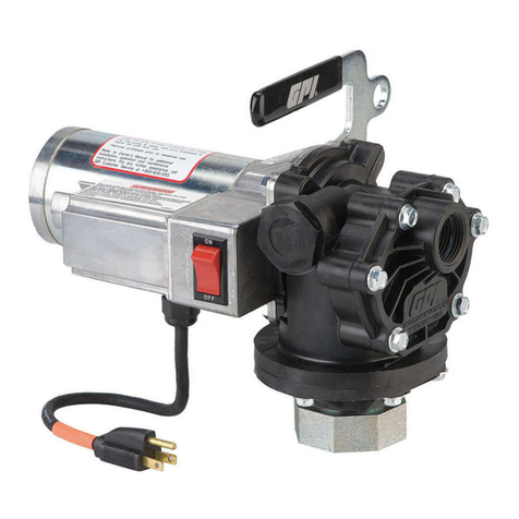
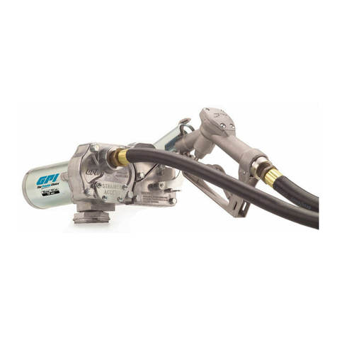
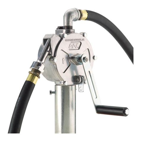
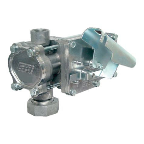
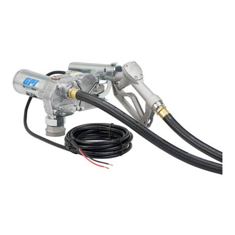
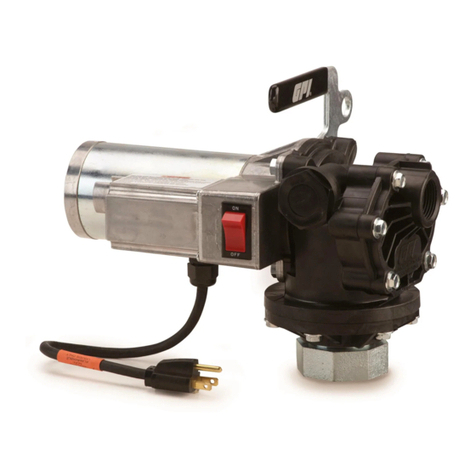
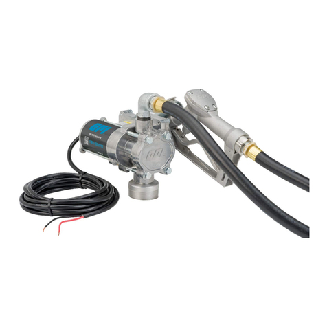
GPI PA-120DEF User manual

TABLE OF CONTENTS
PA-120DEF
115-Volt Plastic Utility Pump
Owner’s Manual
General Information ................................................................2
Safety Instructions ..................................................................2
Installation ..............................................................................3
Operations ..............................................................................3
Maintenance ...........................................................................4
Repair:
PA-120DEF ........................................................................5
P-120DEF ..........................................................................6
Troubleshooting:
PA-120DEF ........................................................................8
P-120DEF ..........................................................................9
Illustrated Parts List:
PA-120DEF ......................................................................10
P-120DEF ........................................................................11
Specifications .......................................................................12
Service ..................................................................................13
Rev. - 9217620101/10
5252 East 36th Street North
Wichita, KS USA 67220-3205
TEL: 316-686-7361
FAX: 316-686-6746
P-120DEF
12-Volt Plastic Utility Pump
PA-120DEF P-120DEF
To the owner...
Congratulations on receiving your GPI pump. We are pleased
to provide you with a system designed to give you maximum
reliability and efficiency.
Your pump is designed, tested, and approved for use with
Diesel Exhaust Fluid (DEF). Please take all due precautions
when handling DEF. Your safety is important to us.
Also, to assure the longest possible service life, it is important
that you follow the operation and maintenance procedures
outlined in this manual. We are proud to provide you with a
quality product and dedicated support. Together with your
conscientious use, we are sure that you will obtain years of
safe, dependable service.
President
Great Plains Industries, Inc.
1

To ensure safe operation, all transfer systems must be
properly grounded. Proper grounding means a continuous
metal-to-metal contact from one component to the next,
including tank, bung, pump, meter, filter, hose and nozzle.
Care should be taken to ensure proper grounding during initial
installation and after any service or repair procedures. For
your safety, please take a moment to review the warnings below.
Observe precautions against electrical shock when operating
the system. Serious or fatal shock can result from operating
electrical equipment in damp or wet locations.
Inspect external pump wiring regularly to make sure it is
correctly attached to power supply. To avoid electrical shock,
use extra care when connecting the pump to power.
Avoid prolonged skin contact with DEF. Use protective goggles,
gloves and aprons in case of splashing or spills. Change satu-
rated clothing and wash skin promptly with soap and water.
Observe precautions against electrical shock when servicing
the pump. Always disconnect power before repairing or ser-
vicing. Never apply electrical power to the system when any
of the coverplates are removed.
PA-120DEF:
• This pump is designed for use with GFCI protected, 115-volt
power. Do not attempt installation or operation with 12-volt,
24-volt, or 230-volt power sources. Use only three-pronged,
grounded connectors. Do not use two-prong adapters.
Inspect power cords regularly and replace if signs of wear
are evident.
• To avoid personal injury, use a ground fault circuit interrupter
(GFCI) approved by Underwriters Laboratories Standard
943 with this pump.
To protect against overload, this pump is equipped with a ther-
mal protector, that resets automatically, and a circuit breaker,
that resets manually. If your pump stops unexpectedly, please
reference further information about the thermal protector and
circuit breaker in the Operations or Troubleshooting Sections.
P-120DEF:
This pump is designed for use with a 12-volt DC battery.
• Inspect wiring regularly. Make sure the power cord is cor-
rectly attached to the battery. To avoid electrical shock,
use extra care when connecting the pump to the battery.
PA-120DEF & P-120DEF:
• Do not exceed standard duty cycle of 30 minutes ON and
30 minutes OFF. Allow the pump to cool for 30 minutes.
• Some fluid may spill from the pump during pump removal.
Follow DEF label directions for cleanup and disposal.
• Do not run the pump more than necessary without flow.
“Dry running” can cause overheating and pump damage.
• To avoid personal injury, turn the pump off and disconnect
from power before repair or service.
• For your protection, thoroughly flush the pump before
cleaning or repair.
When you receive your pump, examine it for visible damage. If any
items are damaged or missing, please contact your distributor.
GENERAL INFORMATION
The purpose of this manual is to assist you in installing, op-
erating and maintaining your GPI pump. It provides information
which will help you achieve years of dependable performance
and trouble-free operation.
The system is approved for DEF (Diesel Exhaust Fluid) only.
Do not use with gasoline, diesel, other flammable fluids, or
micro-encapsulated fluids. Using fluids, other than those for
which the pump was designed, could lead to serious personal
injury and void the warranty.
Before operating your pump, read this manual thoroughly. If
you have problems with your pump in the future, please refer
to the Maintenance and Troubleshooting Sections.
For assistance, contact your dealer or the GPI Customer
Service Department.
The following safety alert symbols are used
in this manual.
DANGER indicates a hazard-
ous situation which, if not
avoided, will result in death
or serious injury.
WARNING indicates a haz-
ardous situation which, if
not avoided, could result in
death or serious injury.
CAUTION indicates a haz-
ardous situation which, if not
avoided, may result in minor
or moderate injury.
It is your responsibility to:
• know and follow applicable national, state, and local safety
codes pertaining to installing and operating electrical
equipment.
• insure that all equipment operators have access to adequate
instructions concerning safe operating and maintenance
procedures.
Observe all safety precautions concerning safe handling of DEF.
2
SAFETY INSTRUCTIONS
DANGER
WARNING
CAUTION

INSTALLATION
3
Figure 1
For proper installation, your pump requires a hose, nozzle and
suction pipe. Kits are available from the factory and are listed
as accessories on the Illustrated Parts List.
Used pumps must be flushed and cleaned before installation
as outlined in the Maintenance Section.
To prevent leaks, seal all connecting threads with 3 to 4 turns
of thread tape during installation.
Before installing the pump, install the suction pipe into bung
adapter on the pump. Tighten the suction pipe into the bottom
of the bung adapter until only three threads are visible.
Installing Pump
The pump has a 2-inch NPS bung adapter with gaskets installed
at the inlet end.
After installing the suction pipe into the bung adapter, insert
the suction pipe into the tank opening and tighten the pump
securely. Make sure the bung adapter threads are not cross-
threaded. (Figure 1)
CAUTION
OPERATIONS
WARNING
WARNING
Figure 2
Using fluids other than those for which the pump was designed
could lead to serious personal injury and void the warranty.
The pump is approved for Diesel Exhaust Fluid only. Do
not use with gasoline, diesel, other flammable fluids, or
micro-encapsulated fluids.
When handling fluids, always wear protective clothing
such as goggles, gloves and respirators, as instructed
by the fluid manufacturer.
Clean any spills from the system exterior as they occur, follow-
ing fluid manufacturer’s instructions.
Before Each Use
1. Keep pump exterior clean to help identify leaks. Before
each use, inspect for leaks around seals or connections.
2. Check for leaks under the pump housing. A small drain
hole relieves any fluid which bypasses the motor shaft seal.
(Figure 2) If any leakage is found here, replace the motor
shaft seal using instructions in the Repair Section.
Install Hose and Nozzle
If installing accessories such as meters or filters, do so before
installing the hose and nozzle. Follow the manufacturer’s in-
structions.
Make sure any hose and nozzle used are compatible
with DEF.
After sealing threads, hand-tighten the hose into the outlet until
snug. Hand-tighten the nozzle to the hose.
3. Make sure hoses are in good condition and connections
are tight.
4. Make sure the work area is dry.
Electrical Connections
PA-120DEF:
This pump is designed for use with GFCI protected, 115-volt
power. Do not attempt to install or operate the pump with 12-
volt, 24-volt or 230-volt power.
Use only three-prong, grounded connectors. Do not use two-
prong connectors or adapters. Inspect power cords regularly
and replace if signs of wear are evident.
To avoid personal injury, use a ground fault circuit interrupter
(GFCI) approved by Underwriters Laboratories Standard 943
with this pump. If your electrical service already had GFCI
outlets, you are protected. If not, a portable GFCI is available
through electrical equipment distributors or from GPI. Contact
your distributor or GPI Customer Service for more information.

4
P-120DEF:
This pump is designed for use with a 12-volt DC battery.
1. Inspect wiring for corrosion or damage. Replace, as neces-
sary.
2. Connect the pump to a 12-volt DC battery with the red
wire attached to positive (+) and the black to negative (–).
PA-120DEF & P-120DEF:
For best results, immediately before use, purge the system of air.
Follow these steps to purge the system of air.
1. Connect the pump to the appropriate power supply
(PA-120DEF to grounded GFCI protected, 115-volt power)
(P-120DEF to a 12-volt DC battery).
2. Place the nozzle in the fill hole of the tank. Turn the pump on.
3. Open the nozzle and pump at full flow until the system is
full of DEF.
4. Close the nozzle and turn the pump off.
NOTE: The PA-120DEF and P-120DEF pumps include an
automatic bypass that will open automatically if internal
pump pressure builds up.
Dispense Fluid
The PA-120DEF and P-120DEF pumps are intended for use
with Diesel Exhaust Fluid (DEF) only.
1. Turn power ON.
2. Insert the nozzle into the receiving tank.
3. Open the nozzle. Always dispense at full flow.
Do not exceed the standard duty cycle of 30 minutes
ON and 30 minutes OFF. Allow the pump to cool for 30
minutes.
4. Dispense the desired amount.
5. Close the nozzle and turn the pump off.
Thermal Protector
PA-120DEF:
This pump’s motor contains an automatic thermal protector.
Excessive motor heat can trip the protector. It resets automati-
cally after the motor has cooled approximately 30 minutes.
Circuit Breaker
PA-120DEF:
The magnetic circuit breaker trips automatically when the
motor draws more than 3 amps. This feature provides added
protection against motor damage and must be reset manually.
When the circuit breaker trips, turn the power off and disconnect
from power before attempting any repairs. Inspect the pump
thoroughly and clean or repair it as necessary.
Make sure the pump switch is in the OFF position before
restoring power.
Reset the circuit breaker after repairs are complete. To reset,
press in on the circuit breaker reset button at the end of the
cover assembly.
Proper cleaning and maintenance is vital to prolong pump life
and promote trouble-free operation.
NOTE: Failure to follow recommended cleaning and storage
procedures increases the chance of pump failure and may
void the warranty.
Remove Pump from Tank
Some fluid may spill from the pump during removal.
Follow DEF label directions for cleanup and disposal.
1. Disconnect pump from power.
2. Loosen the pump from the tank.
3. Lift the pump from the tank.
4. Place the nozzle in the tank.
5. Reconnect the pump to the appropriate power supply
(PA-120DEF to grounded GFCI protected, 115-volt power)
(P-120DEF to a 12-volt DC battery). Open the nozzle to
remove fluids from the system and turn on. Turn pump off
and disconnect from power.
6. Remove the suction pipe, as necessary.
7. Clean fluid from bung adapter or tank nipple and tank.
Cover the bung adapter or tank nipple.
8. If the pump will not be used for more than 2 weeks, flush
to prevent drying of fluids in the pump.
Flush Pump
When the pump will not be used for more than 2 weeks, it must
be flushed to prevent internal drying of fluid.
It is strongly recommended, for protection from personal injury,
that a simple flush tank be created. Use a container with a tight
fitting lid with a minimum volume of 5 gallons (19 litres). Cut two
holes in the lid of this container; one which is approximately 1
inch (2.5cm) larger than the largest diameter of the pump inlet
fitting and a second hole slightly larger than the nozzle tip. Fill
the container with distilled water. Secure the lid tightly on the
top of the container.
1. Disconnect from power. Remove the pump from the tank
and drain using the instructions above.
2. Connect the pump to the appropriate power supply
(PA-120DEF to grounded GFCI protected, 115-volt power)
(P-120DEF to a 12-volt DC battery)
CAUTION
CAUTION
MAINTENANCE
WARNING

5
3. Place the pump inlet and nozzle through the holes in the
top of the flush tank. (Figure 3)
Figure 3
CAUTION
WARNING
4. Open the nozzle and turn the pump on. Circulate distilled
water through the pump for 10 to 15 minutes. Open and
close the nozzle several times to flush the bypass poppet.
5. Lift the pump from the water. Allow the pump to run briefly
until only air passes through the system. Turn the pump
off.
Do not run the pump any longer than necessary without
flow. “Dry running” can cause overheating and pump
damage.
6. Drain the hose and nozzle. Wipe entire system with a clean
damp cloth.
To avoid fluid exposure, follow fluid manufacturer’s
instructions for the disposal of contaminated water.
Clean Pump
If fluid dries inside pump, remove the residue before further use.
1. Disconnect from power, remove the pump from the tank,
and flush.
2. Disassemble the pump as outlined in the Repair Section.
3. Thoroughly clean dried fluid from the interior of the pump.
Take care not to scratch parts.
4. Wash the bypass poppet in distilled water.
5. Assemble the pump.
REPAIR – PA-120DEF
WARNING
WARNING
When handling DEF, always wear protective clothing
such as goggles, gloves, and respirators, as instructed
by the fluid manufacturer.
For your protection, flush system before disassembling.
During repair, carefully inspect all parts for wear or damage and
replace, as necessary. Check O-rings and seals for breakage,
wear, and signs of deterioration, such as swelling.
Clean or Replace Strainer
1. Disconnect pump from power and flush.
2. Remove the coverplate and O-ring from the housing.
3. Remove the strainer.
4. Clean or replace the strainer. Install again.
5. Install the coverplate and O-ring. Torque screws to 25 to
35 in-lbs.
Clean or Replace Inlet Fitting
1. Disconnect pump from power and flush.
2. Remove the inlet fitting from the pump housing.
NOTE: Ensure proper seating of the O-ring between the inlet
fitting and the housing.
3. Clean or replace the inlet fitting. Install again. Torque screws
to 45 to 50 in-lbs.
Clean or Replace Bypass Poppet
1. Disconnect pump from power and flush.
2. Remove the bypass poppet plug.
3. Remove the bypass poppet. Gently rock it back and forth
as necessary to remove.
4. Wipe the cavity clean and wash the bypass poppet in
distilled water.
5. Examine all components and replace as necessary.
6. To replace the poppet O-ring, carefully remove the O-ring
using a small screwdriver or similar tool. Seat new O-ring
on the poppet head.
7. Assemble by placing the bypass poppet assembly in the
cavity. Tighten the plug firmly.

Replace Motor
1. Disconnect pump from power and flush.
2. Remove the four screws holding the motor and handle to
the housing.
3. Lift the motor from the housing and drive shaft.
4. Remove the motor shaft adapter from the drive shaft.
5. Assemble by reversing the steps above. Make sure the
motor is properly seated against the motor adapter seal.
Torque the four screws to 75 to 100 in-lbs.
Replace Switch
1. Disconnect pump from power and flush.
2. Remove the cover assembly on the side of the motor.
3. Press in on the sides of the switch. Push the switch from
the switch box.
NOTE: Before disconnecting wires, note their positions on the
switch. Connect to the new switch in the same positions.
4. Disconnect the terminal wires from the back of the old
switch.
5. Install the new switch by reversing steps above. Carefully
position wires in switch box before replacing cover.
6. Install cover assembly and tighten screws until snug. Do
not overtighten.
Replace the Drive Shaft or Motor Shaft Seal
Follow these steps to remove the drive shaft and motor
shaft seal.
1. Disconnect pump from power and flush.
2. Remove the motor as described above.
3. Carefully slide the drive shaft from the motor and the hous-
ing. Note the position of the motor shaft washer.
4. Carefully pry the motor shaft seal from the housing with a
flat-bladed screwdriver.
NOTE: While removing the motor shaft seal, note carefully the
orientation and which side of the seal faces the motor.
The new seal must be installed with the same orientation.
5. Inspect the drive shaft, motor shaft washer, motor shaft
seal, and bearings for wear. Replace, as necessary.
Follow these steps to install the drive shaft and motor
shaft seal.
1. Press the new motor shaft seal into the housing with the
same orientation as the old seal.
2. Position the motor shaft washer on the seal. Slide the
notched end of the drive shaft into place in the housing.
3. Align the drive shaft with the motor adapter. When properly
aligned, the drive shaft will slip into place with the motor
against the housing.
4. During assembly, make sure the motor is properly seated
against the motor adapter seal and the housing.
6
5. Replace the screws to fasten the motor and handle to the
housing. Use the two longer screws to secure the handle.
Torque to 75 to 100 in-lbs.
Replace Gears or Drive Key
Follow these steps to remove the gears and drive key.
1. Disconnect pump from power and flush thoroughly.
2. Remove the coverplate and O-ring from the housing.
3. Remove the drive key and gears from the housing.
4. Inspect gears and key for wear or damage. Replace, as
necessary. Clean cavity.
Follow the steps below to install gears and drive key.
1. Place a gear over the drive shaft.
2. Align the slotted drive shaft end with the gear.
3. Place the other gear in the housing. Turn the gears to make
sure they do not bind. Carefully place the key in the slot.
4. Replace the O-ring and coverplate. Torque screws to 25
to 35 in-lbs.
Read, understand and follow all safety instructions given at the
front of this manual.
During repair, carefully inspect all parts for wear or damage and
replace, as necessary. Check O-rings and seals for breakage,
wear, and signs of deterioration, such as swelling.
Replace Fuse
1. Locate the fuse holder on the power cord.
2. To remove fuse, push the ends together and twist. Replace
the blown fuse.
Clean or Replace Strainer
1. Disconnect pump from power and flush.
2. Remove the coverplate and O-ring from the housing.
3. Remove the inlet strainer.
4. Clean or replace the strainer. Install again.
5. Install the coverplate and O-ring. Torque screws to 25 to
35 in-lbs.
Clean or Replace Inlet Fitting
1. Disconnect pump from power and flush.
2. Remove the inlet fitting from the pump housing.
3. Clean or replace the inlet fitting. Install again. Torque screws
to 45 to 50 in-lbs.
REPAIR – P-120DEF

7
Clean or Replace Bypass Poppet
1. Disconnect pump from power and flush.
2. Remove the bypass poppet plug.
3. Remove the bypass poppet. Gently rock it back and forth
as necessary to remove.
4. Wipe the cavity clean and wash the bypass poppet in very
pure deionized water.
5. Examine all components and replace as necessary.
6. To replace the poppet O-ring, carefully remove the O-ring
using a small screwdriver or similar tool. Seat O-ring on
the poppet head.
7. Assemble by placing the bypass poppet assembly in the
cavity. Tighten the plug firmly.
Replace Motor
1. Disconnect pump from power and flush.
2. Remove the screws holding the motor and handle to the
housing.
3. Lift the motor from the housing and drive shaft.
4. Remove the motor shaft adapter from the drive shaft.
5. If replacing the motor only, remove the power cord using
instructions below.
6. Assemble by reversing the steps above. Make sure the
motor is properly seated against the motor adapter seal.
Torque the four screws to 75 to 100 in-lbs.
Replace Switch
1. Disconnect pump from power and flush.
2. Remove the switch coverplate on the side of the motor.
3. Press in on the sides of the switch. Push the switch from
the switch box.
NOTE: Before disconnecting wires, note their positions on the
switch. Connect to the new switch in the same positions.
4. Disconnect the terminal wires from the back of the old
switch.
5. Install the new switch by reversing steps above. Carefully
position wires in switch box before replacing coverplate.
6. Install coverplate and tighten screws until snug. Do not
overtighten.
Replace Power Cord
1. Disconnect pump from power and flush.
2. Remove the switch coverplate on the side of the motor.
3. Remove electrical tape and unscrew the wire nut. Remove
wire from terminal on back of the switch.
4. Remove the old power cord.
5. Install new power cord by reversing steps above.
6. Secure wire nut with two wraps of electrical tape.
7. Install coverplate and tighten screws until snug. Do not
overtighten.
Replace the Drive Shaft or Motor Shaft Seal
Follow these steps to remove the drive shaft and motor
shaft seal.
1. Disconnect pump from power and flush.
2. Remove the motor as described above.
3. Carefully slide the drive shaft from the motor and the hous-
ing. Note the position of the motor shaft washer.
4. Carefully pry the motor shaft seal from the housing with a
flat-bladed screwdriver.
5. Inspect the drive shaft, motor shaft washer, motor shaft
seal, and bearings for wear. Replace, as necessary.
Follow these steps to install the drive shaft and motor
shaft seal.
1. Press the new motor shaft seal into the housing with the
same orientation as the old seal.
2. Position the motor shaft washer on the seal. Slide the
notched end of the drive shaft into place in the housing.
3. Align the drive shaft with the motor adapter or the planetary
gear module. When properly aligned, the drive shaft will
slip into place with the motor against the housing.
4. During assembly, make sure the motor is properly seated
against the motor adapter seal and the housing.
5. Replace the screws fastening the motor and handle to the
housing. Use the two longer screws to secure the handle.
Torque to 75 to 100 in-lbs.
Replace Gears or Drive Key
Follow these steps to remove the gears and drive key.
1. Disconnect pump from power and flush thoroughly.
2. Remove the coverplate and O-ring from the housing.
3. Remove the drive key and gears from the housing.
4. Inspect gears and key for wear or damage. Replace, as
necessary. Clean cavity.
Follow the steps below to install gears and drive key.
1. Place a gear over the drive shaft.
2. Align the slotted drive shaft end with the gear.
3. Place the other gear in the housing. Turn the gears to make
sure they do not bind. Carefully place the key in the slot.
4. Replace the O-ring and coverplate. Torque screws to 25
to 35 in-lbs.

8
TROUBLESHOOTING – PA-120DEF
SYMPTOM PROBABLE CAUSE CORRECTIVE ACTION
A. MOTOR DOES NOT 1. Circuit breaker tripped Manually reset circuit breaker located in cover assembly. See Operations
RUN Section.
2. Switch defective Remove cover assembly and inspect switch. Replace, if necessary.
3. Motor burned out Remove motor and test by making grounded connection to GFCI protected
115-volt power. Replace, if necessary.
4. Thermal protector tripped Turn switch off. Allow motor to cool. Protector resets automatically after
approximately 30 minutes. See Operations Section.
5. GFCI tripped Manually reset GFCI. If motor does not run, disconnect power and check for wet
or damaged pump or power cord. Correct problem before resuming operation.
Operate pump only in dry locations.
B. MOTOR RUNS BUT 1. System air leak Make sure all fittings and connections are tight. Inspect suction pipe, bung
DOES NOT PUMP adapter and pump inlet seals for leaks or damage.
FLUID
2. Drive key broken Replace key.
3. Strainer clogged Remove coverplate. Clean strainer. Install again.
4. Gear coverplate O-ring worn Remove coverplate. Inspect O-ring and replace if worn or damaged.
5. Bypass poppet stuck open Remove poppet and clean. Install again.
6. Suction pipe clogged, Remove pump. Inspect suction pipe and clean or replace, as necessary.
damaged or missing
7. Gear drive shaft broken Remove coverplate, gears, and motor. Remove and inspect drive shaft.
Replace, if necessary.
8. Gear wear Remove the coverplate and inspect gears, and drive key. Gears must turn freely
with the drive key removed. Replace any worn or damaged parts.
C. LOW FLOWRATE 1. Low voltage Check for adequate power supply voltage.
2. Strainer partially clogged Remove coverplate. Clean strainer. Install again.
3. Suction pipe clogged or Remove pump from tank. Inspect suction pipe and clean or replace, as
damaged necessary.
4. Bypass poppet stuck open Remove poppet and clean. Install again.
5. Gear wear Remove the coverplate and inspect gears, and drive key. Gears must turn freely
with the drive key removed. Replace any worn or damaged parts.
6. Discharge hose too long Long hoses reduce flowrate. Shorten hose.
7. Extension cord too long Long cords reduce voltage at pump. Reduce cord length or use larger gauge
cord.
D. RAPID OVERHEATING 1. Duty cycle too long Do not exceed the standard duty cycle of 30 minutes ON and 30 minutes OFF.
OF MOTOR Allow the pump to cool for 30 minutes.
2. Strainer clogged Remove coverplate. Clean strainer. Install again.
3. Thermal protector tripped Turn switch off. Allow motor to cool. Protector resets automatically after
approximately 30 minutes. See Operations Section.

9
TROUBLESHOOTING – P-120DEF
SYMPTOM PROBABLE CAUSE CORRECTIVE ACTION
A. MOTOR DOES NOT 1. Fuse blown Inspect fuse. If blown, replace.
2. Switch defective Remove switch coverplate and inspect switch. Replace, if necessary.
3. Motor burned out Remove motor from pump and test by connecting to 12-volt DC power supply.
Replace if necessary.
B. MOTOR RUNS BUT 1. System air leak Make sure all fittings and connections are tight. Inspect suction pipe, bung
DOES NOT PUMP adapter and pump inlet seals for leaks or damage.
FLUID
2. Drive key broken Replace key.
3. Strainer clogged Remove coverplate. Clean strainer. Install again.
4. Gear coverplate O-ring worn Remove coverplate. Inspect O-ring and replace if worn or damaged.
5. Bypass poppet stuck Remove poppet and clean. Install again.
6. Suction pipe clogged, Remove pump. Inspect suction pipe and clean or replace, as necessary.
damaged or missing
7. Gear drive shaft broken Remove coverplate, gears, and motor. Remove and inspect drive shaft.
Replace, if necessary.
8. Gear wear Remove the coverplate and inspect gears, and drive key. Gears must turn freely
with the drive key removed. Replace any worn or damaged parts.
C. LOW FLOWRATE 1. Low voltage or poor Check for adequate battery voltage and good terminal connections.
connections
2. Strainer partially clogged Remove coverplate. Clean strainer. Install again.
3. Suction pipe clogged or Remove pump from tank. Inspect suction pipe and clean or replace, as
damaged necessary.
4. Bypass poppet stuck Remove poppet and clean. Install again.
5. Gear wear Remove the coverplate and inspect gears, and drive key. Gears must turn freely
with the drive key removed. Replace any worn or damaged parts.
6. Discharge hose too long Long hoses reduce flowrate. Shorten hose.
7. Power cord too long Long cords reduce flowrate. Shorten cord.
D. RAPID OVERHEATING 1. Duty cycle too long Do not exceed the standard duty cycle of 30 minutes ON and 30 minutes OFF.
OF MOTOR Allow the pump to cool for 30 minutes.
2. Strainer clogged Remove coverplate. Clean strainer. Install again.

10
ILLUSTRATED PARTS LIST – PA-120DEF
Item No.n
No. Part No. Description Req’d.
15 118023-1 Handle Grip ................................................................ 1
16 119006-1 Motor Assembly ......................................................... 1
17 119107-1 Cover Assembly (standard) ........................................ 1
18 902002-91 Rocker Switch w/gasket ............................................ 1
19 904001-99 Screw, Pan HD Mach, #8-32 x 5/16" ......................... 4
20 901001-91 O-Ring ........................................................................ 1
21 904002-24 Sems Screw & Washer Assembly .............................. 2
22 904003-49 Sems, Hex HD, 1/4-20 x 1 & Flat Washer .................. 6
23 904003-70 Flat Washer, 5/16" ID x 1" OD x .0303 ....................... 1
24 904003-92 Sems, Hex HD, 5/16-18 x 7/8, INT Lockwash ........... 2
25 118108-2 Bung Adapter, 2 in. NPS (Pup) .................................. 1
26 901002-38 O-Ring, Fluorocarbon ................................................ 1
27 904003-91 Sems, Hex HD, 1/4-20 x 3/4, Plain Washer ............... 6
Item No.n
No. Part No. Description Req’d.
1 110100-1 Suction Pipe Assembly, Adjustable ........................... 1
2 117204-1 Fitting, Reducer Bushing, 1" x 3/4" NPT ................... 1
3 115084-1 Gasket, 2 in. ............................................................... 1
4 115085-1 Teflon
®
Ring ................................................................ 1
5 110017-6 Motor Shaft Key ......................................................... 1
6 110063-2 Inlet Strainer ............................................................... 1
7 110078-8 Motor Shaft Seal ........................................................ 1
8 110204-2 Drive Shaft Assembly ................................................. 1
9 118006-1 Pump Housing ........................................................... 1
10 118007-1 Gear Coverplate ......................................................... 1
11 118016-1 Shaft Adapter ............................................................. 1
12 118017-1 O-Ring ........................................................................ 1
13 118020-1 Bearing ....................................................................... 2
14 118021-1 Handle ........................................................................ 1
Kits and Accessories
118508-2 Bypass Poppet Assembly Kit (Automatic bypass)
118501-1 Gear Kit (Includes two gears and key)
906006-83 3/4 in. NPT DEF Automatic Nozzle
90600658 3/4 in. NPT Ball Valve with 45 Degree Spout
A
NOT SHOWN:
118505-1 Drive Shaft Kit (Includes two bearings, motor shaft seal, motor
shaft washer, drive shaft assembly and motor adapter seal
150200-01 DEF Hose, 3/4 in. NPT x 3/4 in. x 12 ft. (3.7m)
C
D
B

11
ILLUSTRATED PARTS LIST – P-120DEF
Item No.n
No. Part No. Description Req’d.
16 119002-17 Motor Assembly (12V) P-120H, Standard CSA .......... 1
17 115016-11 Power Cord Assembly, CSA (14 gauge) .................... 1
18 119077-2 Switch Coverplate ...................................................... 1
19 902002-91 Rocker Switch w/gasket ............................................ 1
20 902004-12 Strain Relief ................................................................ 1
21 904001-99 Screw, Pan HD Mach, #8-32 x 5/16" ......................... 4
22 901001-91 O-Ring ........................................................................ 1
23 904002-24 Sems Screw & Washer Assembly .............................. 2
24 904003-49 Sems, Hex HD, 1/4-20 x 1 & Flat Washer .................. 6
25 904003-70 Flat Washer, 5/16" ID x 1" OD x .0303 ....................... 1
26 904003-92 Sems, Hex HD, 5/16-18 x 7/8, INT Lockwash ........... 2
27 118108-2 Bung Adapter, 2 in. NPS (Pup) .................................. 1
28 901002-38 O-Ring, Fluorocarbon ................................................ 1
29 904003-91 Sems, Hex HD, 1/4-20 x 3/4, Plain Washer ............... 6
Item No.n
No. Part No. Description Req’d.
1 110100-1 Suction Pipe Assembly, Adjustable ........................... 1
2 117204-1 Fitting, Reducer Bushing, 1" x 3/4" NPT ................... 1
3 115084-1 Gasket, 2 in. ............................................................... 1
4 115085-1 Teflon
®
Ring ................................................................ 1
5 110017-6 Motor Shaft Key ......................................................... 1
6 110063-2 Inlet Strainer ............................................................... 1
7 110078-8 Motor Shaft Seal ........................................................ 1
8 110204-2 Drive Shaft Assembly ................................................. 1
9 118006-1 Pump Housing ........................................................... 1
10 118007-1 Gear Coverplate ......................................................... 1
11 118016-1 Shaft Adapter ............................................................. 1
12 118017-1 O-Ring ........................................................................ 1
13 118020-1 Bearing ....................................................................... 2
14 118021-1 Handle ........................................................................ 1
15 118023-1 Handle Grip ................................................................ 1
Kits and Accessories
118508-2 Bypass Poppet Assembly Kit (Automatic bypass)
118501-1 Gear Kit (Includes two gears and key)
906006-83 3/4 in. NPT DEF Automatic Nozzle
90600658 3/4 in. NPT Ball Valve with 45 Degree Spout
A
NOT SHOWN:
118505-1 Drive Shaft Kit (Includes two bearings, motor shaft seal, motor
shaft washer, drive shaft assembly and motor adapter seal
150200-01 DEF Hose, 3/4 in. NPT x 3/4 in. x 12 ft. (3.7m)
C
D
B

12
SPECIFICATIONS
PA-120DEF:
Applications
Fluids: Diesel Exhaust Fluid (DEF)
Operating Environment: Outdoor, operating temperature range
of –20° to +120° F (–30° to +50° C).
Operating Pressure
10 PSI
Pump Housing
Lightweight, durable, molded plastic housing.
Convenient 2-inch NPS bung adapter for easy
installation.
Performance
Pump Rate: Up to 12 GPM (45 LPM). Rate will vary with
temperature.
Duty Cycle: 30 minutes ON, 30 minutes OFF. Duty cycle will
vary with temperature.
Electrical Specifications
Input: 115-volt AC, grounded, GFCI protected
Cord: 18 gauge, 3 wire, grounded plug equipped with circuit
breaker.
Mechanical Connections
Bung: 2 inch NPS
Inlet: 1 inch NPT
Outlet: 1 inch NPT
Recommended Accessories
3/4 in. x 12 ft. (3.7m) DEF discharge hose
3/4 in. NPT DEF automatic nozzle
3/4 in. NPT DEF ball valve
Weight
Shipping: 15 lbs. (6.8kg)
P-120DEF:
Applications
Fluids: Diesel Exhaust Fluid (DEF)
Operating Environment: Outdoor, operating temperature range
of –20° to +120° F (–30° to +50° C).
Operating Pressure
10 PSI
Pump Housing
Lightweight, durable, molded plastic housing.
Convenient 2-inch NPS bung adapter for easy
installation.
Performance
Pump Rate: Up to 12 GPM (45 LPM). Rate will vary with
temperature.
Duty Cycle: 30 minutes ON, 30 minutes OFF. Duty cycle will
vary with temperature.
Electrical Specifications
Input: 12-volt DC
Current: 12-15 amps
Cord: 14 gauge, 15 ft. (4.6m)
Fuse: 20 amps AGC
Mechanical Connections
Bung: 2 inch NPS
Inlet: 1 inch NPT
Outlet: 1 inch NPT
Recommended Accessories
3/4 in. x 12 ft. (3.7m) DEF discharge hose
3/4 in. NPT DEF automatic nozzle
3/4 in. NPT DEF ball valve
Weight
Shipping: 15 lbs. (6.8kg)

13
For warranty consideration, parts or other service informa-
tion, please contact your local distributor. If you need further
assistance, contact the GPI Customer Service Department in
Wichita, Kansas, during normal business hours.
A toll free number is provided for your convenience.
1-800-835-0113
To obtain prompt, efficient service, always be prepared with the
following information:
• The model number of your pump
• The serial number or manufacturing date code of your pump
• Parts descriptions and numbers
Part information can be obtained from the Illustrated Parts List.
For warranty work, always be prepared with your original sales
slip or other evidence of purchase date.
Please contact GPI before returning any parts. It may be possible
to diagnose the trouble and identify needed parts in a telephone
call. GPI can also inform you of any special requirements you will
need to follow for transportation and handling of fluid equipment.
Do not return the pump or parts without authority from the
Customer Service Department. Due to strict government
regulations, GPI cannot accept parts unless they have been
drained and cleaned.
SERVICE
CAUTION


©2010 by GREAT PLAINS INDUSTRIES, INC., Wichita, KS
Printed in U.S.A.
01/10 Rev. - 92176201
5252 East 36th Street North
Wichita, KS USA 67220-3205
TEL: 316-686-7361
FAX: 316-686-6746
Limited Warranty Policy
Great Plains Industries, Inc. 5252 E. 36
th
Street North, Wichita, KS USA 67220-3205, hereby provides a limited warranty against defects in
material and workmanship on all products manufactured by Great Plains Industries, Inc. This product includes a 2 year warranty from date
of purchase as evidenced by the original sales receipt. A 30 month warranty from product date of manufacture will apply in cases where the
original sales receipt is not available. Reference product labeling for the warranty expiration date based on 30 months from date of manufacture.
Manufacturer’s sole obligation under the foregoing warranties will be limited to either, at Manufacturer’s option, replacing or repairing defective
Goods (subject to limitations hereinafter provided) or refunding the purchase price for such Goods theretofore paid by the Buyer, and Buyer’s
exclusive remedy for breach of any such warranties will be enforcement of such obligations of Manufacturer. The warranty shall extend to the
purchaser of this product and to any person to whom such product is transferred during the warranty period.
This warranty shall not apply if:
A. the product has been altered or modified outside the warrantor’s duly appointed representative;
B. the product has been subjected to neglect, misuse, abuse or damage or has been installed or operated other than in accordance
with the manufacturer’s operating instructions.
To make a claim against this warranty, contact the GPI Customer Service Department at 316-686-7361 or 800-835-0113. Or by mail at:
Great Plains Industries, Inc.
5252 E. 36
th
St. North
Wichita, KS, USA 67220-3205
GPI will step you through a product troubleshooting process to determine appropriate corrective actions.
GREAT PLAINS INDUSTRIES, INC., EXCLUDES LIABILITY UNDER THIS WARRANTY FOR DIRECT, INDIRECT, INCIDENTAL AND CONSE-
QUENTIAL DAMAGES INCURRED IN THE USE OR LOSS OF USE OF THE PRODUCT WARRANTED HEREUNDER.
The company herewith expressly disclaims any warranty of merchantability or fitness for any particular purpose other than for which it was
designed.
This warranty gives you specific rights and you may also have other rights which vary from U.S. state to U.S. state.
Note: In compliance with MAGNUSON MOSS CONSUMER WARRANTY ACT – Part 702 (governs the resale availability of the warranty terms).
This manual suits for next models
1
Table of contents
Other GPI Water Pump manuals
Popular Water Pump manuals by other brands

Bell and Gossett
Bell and Gossett NRF-25 Installation, operation and maintenance manual

Ingersoll-Rand
Ingersoll-Rand NM2328A-X Operator's manual

Walrus
Walrus TPK Series Replacing

Pacific hydrostar
Pacific hydrostar 68390 manual

Wilden
Wilden P220 ENGINEERING OPERATION & MAINTENANCE MANUAL

Grundfos
Grundfos SQFlex 11 SQF-2 instructions