manuals.online logo
Brands
  1. Home
  2. •
  3. Brands
  4. •
  5. Siemens
  6. •
  7. Controllers
  8. •
  9. Siemens N350E Service manual

Siemens N350E Service manual

Other Siemens Controllers manuals

Siemens LOGO! PROM User manual

Siemens

Siemens LOGO! PROM User manual

Siemens SINUMERIK 840D Operating instructions

Siemens

Siemens SINUMERIK 840D Operating instructions

Siemens RVP550 User manual

Siemens

Siemens RVP550 User manual

Siemens SIRIUS 3RW40 5 User manual

Siemens

Siemens SIRIUS 3RW40 5 User manual

Siemens SSA955 User manual

Siemens

Siemens SSA955 User manual

Siemens SIRIUS 3RW40 2 User manual

Siemens

Siemens SIRIUS 3RW40 2 User manual

Siemens instabus JB 527C23 User manual

Siemens

Siemens instabus JB 527C23 User manual

Siemens 7SR224 Use and care manual

Siemens

Siemens 7SR224 Use and care manual

Siemens Reyrolle 7SR45 User manual

Siemens

Siemens Reyrolle 7SR45 User manual

Siemens SIPART DR19 User manual

Siemens

Siemens SIPART DR19 User manual

Siemens RMH760 User manual

Siemens

Siemens RMH760 User manual

Siemens CPU 410-5H Process Automation User guide

Siemens

Siemens CPU 410-5H Process Automation User guide

Siemens MEC 1100 User manual

Siemens

Siemens MEC 1100 User manual

Siemens DXR2.E10PL-102B User manual

Siemens

Siemens DXR2.E10PL-102B User manual

Siemens GDB 1 Series User manual

Siemens

Siemens GDB 1 Series User manual

Siemens SIMATIC S7-200 User guide

Siemens

Siemens SIMATIC S7-200 User guide

Siemens RWF40.000A97 User manual

Siemens

Siemens RWF40.000A97 User manual

Siemens Simatic S7-1500 User manual

Siemens

Siemens Simatic S7-1500 User manual

Siemens Albatros2 RVA78.690 User manual

Siemens

Siemens Albatros2 RVA78.690 User manual

Siemens 3VA9 Series User manual

Siemens

Siemens 3VA9 Series User manual

Siemens PolyCool CPS 40 User manual

Siemens

Siemens PolyCool CPS 40 User manual

Siemens SIMATIC S7-200 User manual

Siemens

Siemens SIMATIC S7-200 User manual

Siemens RVP360 Operator's manual

Siemens

Siemens RVP360 Operator's manual

Siemens SITRANS S7-300 User manual

Siemens

Siemens SITRANS S7-300 User manual

Popular Controllers manuals by other brands

Sunricher SR-ZV9003T3-RGBW-US Installation

Sunricher

Sunricher SR-ZV9003T3-RGBW-US Installation

Ksenia intro Installation and configuration manual

Ksenia

Ksenia intro Installation and configuration manual

Inovance CAN200 Series manual

Inovance

Inovance CAN200 Series manual

Gauzy LC6 FLEX Controller Installation and operation guide

Gauzy

Gauzy LC6 FLEX Controller Installation and operation guide

Viking SLP-1 Technical practice

Viking

Viking SLP-1 Technical practice

CKD KBX-30E-U Series instruction manual

CKD

CKD KBX-30E-U Series instruction manual

Sharp Energy Sun Flux User manual & installation guide

Sharp Energy

Sharp Energy Sun Flux User manual & installation guide

Yamaha RCX40 user manual

Yamaha

Yamaha RCX40 user manual

AB Quality PowerFlex 400 Frames D-H Service bulletin

AB Quality

AB Quality PowerFlex 400 Frames D-H Service bulletin

Yamaha MJC8 owner's manual

Yamaha

Yamaha MJC8 owner's manual

AL-KO ATC operating instructions

AL-KO

AL-KO ATC operating instructions

Savant SmartControl 2 Deployment guide

Savant

Savant SmartControl 2 Deployment guide

GameSir T3S user manual

GameSir

GameSir T3S user manual

Kostal inveor operating manual

Kostal

Kostal inveor operating manual

Emerson Yarway 20-55 Operating and safety instructions

Emerson

Emerson Yarway 20-55 Operating and safety instructions

CoCo ACM-LV24 Quick installation guide

CoCo

CoCo ACM-LV24 Quick installation guide

Brooks SLA5810/20 Installation and operation manual

Brooks

Brooks SLA5810/20 Installation and operation manual

SIGMA TEK SR 011 Technical manual

SIGMA TEK

SIGMA TEK SR 011 Technical manual

manuals.online logo
manuals.online logoBrands
  • About & Mission
  • Contact us
  • Privacy Policy
  • Terms and Conditions

Copyright 2025 Manuals.Online. All Rights Reserved.

GAMMA instabus
IP Controller N350E 5WG1 350-1EB01
N350E
Bedien- und Montageanleitung
Operating and Mounting Instructions
Stand: Oktober 2004
Issued: October 2004
D
Produkt- und Funktionsbeschreibung
Der IP Controller N350E ist ein Reiheneinbaugerät zur Montage
auf DIN Hutschienen.
Er bietet folgende Funktionen:
• Wochenzeitschaltuhr mit bis zu 100 Zeitschaltbefehlen für
bis zu 80 Kanäle
• 30 Logikgatter
• Ereignisprogramme mit insgesamt bis zu 200 Befehlen
• Ereignisprogrammauslösung über Logikfunktionen
oder bis zu 30 Schwellwertschaltern
• Konfiguration der Zeitschaltuhrfunktionen, Ereignisprogram-
me und Logikfunktionen über IP Netzwerk
(verwendetes Protokoll: EIBnet/IP Device Configuration)
• Batteriegepufferte Echtzeituhr
• Anzeige von Uhrzeit und Datum über LC-Display
• Echtzeituhreinstellung manuell über 3 Tasten oder automa-
tisch durch einen Zeitdienst im Internet
• Zeitzone für automatische Zeitsynchronisation einstellbar
• Automatische Sommer-/Winterzeitumstellung einstellbar
• DHCP für automatische IP Adresszuweisung
• Kommunikation mit einer Visualisierungssoftware über IP
Netzwerk
Über die ETS werden im Gerät bis zu 80 Objekte mit freier Da-
tentypzuordnung mit den Möglichkeiten
• 1 bit (EIS1)
• 1 Byte ohne Vorzeichen (EIS 14)
• 1 Byte mit Vorzeichen (EIS 14)
• 2 Byte ohne Vorzeichen (EIS 10)
• 2 Byte mit Vorzeichen (EIS 10)
• 2 Byte float (EIS 5)
• 4 Byte ohne Vorzeichen (EIS 11)
• 4 Byte mit Vorzeichen (EIS 11)
• 4 Byte float (EIS 9)
definiert.
Alle definierten Objekte können wahlweise von allen zur Verfü-
gung stehenden Modulen genutzt werden.
Dementsprechend können bis zu 80 Objekte für eine Zeitschalt-
funktion, als Eingang einer Logikfunktion, als Auslöseobjekte
oder als Ausgänge der Ereignisprogramme gewählt werden.
Mit Hilfe der ETS (EIB Tool Software) kann das Applikationspro-
gramm ausgewählt, die spezifischen Parameter und Adressen
vergeben und in den IP Controller N350E übertragen werden.
Weitere Informationen
http://www.siemens.de/gamma
Technische Daten
Spannungsversorgung
• Busspannung: erfolgt über die EIB Buslinie
• Betriebsspannung:
aus externer Sicherheitskleinspannung AC/DC 24V nominal,
zulässiger Eingangsspannungsbereich:
AC/DC 12 ... 30 V
• Empfohlene Spannungsversorgungen:
– unverdrosselte Spannung aus EIB Spannungsversorgun-
gen N123 und N125/21
– Klingeltransformator 4AC2 102, AC 230V / AC 12 V (primär
/ sekundär), 1,33A, 2TE breit
– Klingeltransformator 4AC2 105, AC 230V / AC 12 V (primär
/ sekundär), 1,33A, 2TE breit
Anschlüsse
• Buslinie: Busklemme (schwarz-rot), schraubenlos
0,6...0,8mm Ø eindrähtig
Abisolierlänge 5mm
• Ethernet 10BaseT / IP Netzwerk: RJ45 Buchse
• Spannungsversorgung:
Busklemme (gelb-weiss), schraubenlos
0,6...0,8mm Ø eindrähtig
Abisolierlänge 5mm
Mechanische Daten
• Abmessungen: Reiheneinbaugerät,
Breite 4 TE (1 TE = 18 mm), Höhe 55 mm
• Gewicht: 150 g
Elektrische Sicherheit
• Schutzart (nach EN 60529): IP 20
Umweltbedingungen
• Klimabeständigkeit: EN 50090-2-2
• Umgebungstemperatur im Betrieb: 0 ... + 45 °C
• Lagertemperatur: - 25 ... + 70 °C
• rel. Feuchte (nicht kondensierend): 5 % bis 93 %
Seite 1 von 2
GB
Product and Applications Description
The IP Controller N350E is a DIN rail mounted device.
It provides these functions:
• Weekly scheduler for up to 100 schedules and up to 80
channels
• 30 Logic gates
• Event programs with a total of up to 200 event actions
• Event program trigger via logic functions or up to 30 thresh-
old value switches
• Configuration of scheduler functions, event programs, and
logic functions via IP network
(protocol used: EIBnet/IP Device Configuration)
• Battery buffered real-time clock
• Display of date and time on LC-display
• Real-time clock setting manually with three push buttons or
automatically by a network (Internet) time service
• Time zone selection for automatic time synchronization
• Automatic Daylight Savings Time change-over selectable
• DHCP for automatic IP address assignment
• Communication with visualization software via IP Netzwerk
Via ETS up to 80 objects can be defined for the device with free
data type assignment from this list of data types
• 1 bit (EIS1)
• 1 Byte, unsigned (EIS 14)
• 1 Byte, signed (EIS 14)
• 2 Byte, unsigned (EIS 10)
• 2 Byte, signed (EIS 10)
• 2 Byte, float (EIS 5)
• 4 Byte, unsigned (EIS 11)
• 4 Byte, signed (EIS 11)
• 4 Byte, float (EIS 9)
All defined objects can be used freely by all software modules.
Hence, up to 80 objects can be selected from for schedule
functions, as input for logic gates, as event triggers, or as out-
put of event programs (scenes).
With the ETS (EIB Tool Software) the application program is se-
lected, its parameters and addresses are assigned appropri-
ately, and downloaded to the IP Controller N350E.
Additional Information
http://www.siemens.com/gamma
Technical Specifications
Power supply
• Bus voltage: via EIB bus line
• Operating voltage:
from external SELV power supply AC/DC 24V nominal,
permissible input voltage range:
AC/DC 12 ... 30 V
• Recommended power supplies:
– DC 24V (before choke) from EIB power supplies N121,
N122, N125/21
– door bell transformer 4AC2 102, AC 230V / AC 12V (pri-
mary / secondary), 1,33A, 2SU width
– door bell transformer 4AC2 105, AC 230V / AC 12V (pri-
mary / secondary), 1,33A, 2SU width
Connections
• bus line:
screwless bus connection block (red-black)
0,6...0,8 mm Ø single core
remove approx. 5mm of isolation
• Ethernet / IP network: RJ45 socket
• auxiliary power:
screwless extra low voltage terminal (yellow-white)
∅0,6 ... 0,8 mm Ø single core
remove approx. 5mm of isolation
Physical specifications
• DIN-rail mounted device,
width: 2 SUs (1SU = 18mm), height 55 mm
• weight: approx. 150g
Electrical safety
• protection (according to EN 60529): IP 20
Environmental specifications
• climatic conditions: EN 50090-2-2
• ambient temperature operating: 0 ... + 45 °C
• ambient temperature non-op.: - 25 ... + 70 °C
• relative humidity (non-condensing): 5 % to 93 %
page 1 of 2 251503.41.70 „a“
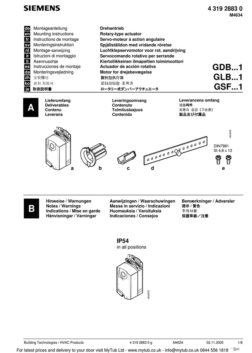
Lage- und Funktion der Anzeige- und Bedienelemente
A1 AC/DC 24 V Busklemme
A2 EIB Busklemme
A3 Ethernet RJ45 Stecker
A4 EIB Programmier LED
A5 EIB Lerntaste
A6 Display 2x12 Zeichen
A7 MOVE-Taste
A8 Set/Prg-Taste
A9 ESC-Taste
A10 Ethernet Link LED
A11 Ethernet Activity LED
A12 Batteriefach
Einstellung von Datum und Uhrzeit
Im Anzeigemodus zeigt das LC-Display Uhrzeit, Wochentag und
Datum an. Durch Drücken der Set/Prg-Taste (A8) wird in den
Einstellungsmodus umgeschaltet. Nacheinander können Stunde
– Minute – Tag – Monat – Jahr eingestellt werden.
Durch Drücken der Taste Move (A7) wird der Wert des jeweili-
gen Zeit-/Datumswertes um eins erhöht bzw nach Erreichen
des Maximalwertes auf den kleinsten Wert gesetzt. Wenn der
korrekte Wert erreicht ist, drücken Sie die Prg/Set-Taste (A8),
um zur Einstellung des nächsten Zeit-/Datumswertes zu gehen.
Nach Eingabe des Jahres drücken Sie die Prg/Set-Taste (A8).
Der Einstellmodus wird automatisch nach ca. fünf Sekunden
verlassen.
Der Einstellmodus kann durch Drücken der ESC Taste (A9) ver-
lassen werden.
Montage und Verdrahtung
Allgemeine Beschreibung
Das Reiheneinbaugerät kann in Niederspannungsverteilern (Auf-
Putz oder Unter-Putz) und überall dort eingesetzt werden, wo
Hutschienen nach EN 60715-TH35-7,5 vorhanden sind.
Die Verbindung mit der Buslinie erfolgt über eine Busklemme.
Zur Verbindung mit dem Ethernet-IP Datennetzwerk verfügt das
Gerät über eine RJ45 Buchse.
Montage
− Schnappen Sie den IP Controller N350E auf die Hutschiene
auf.
− Verbinden Sie die Hilfsspannung AC/DC 24V mit der gelb-
weißen Busklemme (A1).
− Verbinden Sie die Busleitung mit der schwarz-roten Bus-
klemme (A2).
− Stecken Sie ein Ethernet Patchkabel mit RJ45 Stecker in die
RJ45 Buchse (A3), um das Gerät mit dem LAN / Intranet zu
verbinden.
Es besteht eine Verbindung zu einem Netzwerk, wenn die
gelbe LED mit der Kennzeichnung LK (A10) dauernd leuchtet.
Wenn die LED LA (A11) aufleuchtet, werden Daten vom bzw
zum Gerät gesendet.
Demontage
− Entfernen Sie zuerst das Ethernet Patchkabel aus der RJ45
Buchse (A3).
− Entfernen Sie die gelb-weiße Busklemme (A1) aus der Buch-
se.
− Entfernen Sie die schwarz-rote Busklemme (A2) aus der
Buchse.
− Lösen Sie den Schnapper und heben das Gerät von der Hut-
schiene.
Batteriewechsel
− Heben Sie den Batteriefachdeckel (A12) mit einem Schrau-
bendreher ab.
− Entnehmen Sie die Batterie mit dem Batteriehalter.
− Trennen Sie die alte Batterie vorsichtig vom Batteriehalter, in
den diese eingeklebt ist.
− Legen Sie die neue Batterie in den Batteriehalter und ste-
cken beide in das Batteriefach. Achten Sie auf die richtige
Polung (+ Zeichen beachten), um eine korrekte Funktion zu
gewährleisten.
− Drücken Sie den Batteriefachdeckel (A12) wieder auf die
Öffnung.
− Batterietyp: Lithiumbatterie CR 123A
VWARNUNG
• Das Gerät darf nur von einer zugelassenen Elektrofachkraft
installiert und in Betrieb genommen werden.
• Freie Hutschienenbereiche mit eingelegter Datenschiene
sind mit der Abdeckung 5WG1 192-8AA01
abzudecken.
• Die geltenden Sicherheits- und Unfallverhütungsvorschriften
sind zu beachten.
• Das Gerät darf nicht geöffnet werden.
• Bei der Planung und Errichtung von elektrischen Anlagen
sind die einschlägigen Richtlinien, Vorschriften und Bestim-
mungen des jeweiligen Landes zu beachten.
Allgemeine Hinweise
• Die Bedienungsanleitung ist dem Kunden auszuhändigen.
• Ein defektes Gerät ist an die zuständige Geschäftsstelle der
Siemens AG zu senden.
• Bei zusätzlichen Fragen zum Produkt wenden Sie sich bitte
an unseren Technical Support:
!+49 (180) 5050-222
!+49 (180) 5050-223
"[email protected]
#www.siemens.de/automation/support-request
Seite 2 von 2
Location and Function of the Display and Operating Elements
A1 AC/DC 24 V bus connector terminal (yellow-white)
A2 EIB bus connector terminal (black-red)
A3 Ethernet RJ45 socket
A4 EIB programming LED
A5 EIB learning button
A6 Display 2x12 characters
A7 MOVE push button
A8 Set/Prg push button
A9 ESC push button
A10 Ethernet Link LED
A11 Ethernet Activity LED
A12 Battery case
Setting time and date
In the display mode the LC-display shows time, day of week,
and date. Switch to the setup mode by depressing the Set/Prg-
push button (A8). Hour – Minute – Day – Month – Year can be
set in this order. Move from one to the next with the Set/Prg-
push button (A8). The selected time/date value can be set by
depressing the Move push button (A7). Scroll through until the
correct value is displayed and then press the Set/Prg-push but-
ton (A8) to move to the next time/date value.
After you entered the value for the year press the Set/Prg-push
button (A8). The device automatically leaves the setup mode af-
ter approximately five seconds.
The setup mode can be left by pressing the ESC push button
(A9).
Mounting and wiring
General description
The N-system DIN-rail device can be installed in distribution
boards, surface or flush mounted, or on any DIN rail complying
with EN 60715-TH35-7,5.
The connection to the bus line is established via the bus con-
nector terminal (red-black) on the top side.
The RJ45 socket on the device front side provides the connec-
tion to the Ethernet-IP data network.
Mounting
− Snap the IP Controller N350E onto the DIN rail.
− Connect the auxiliary power AC/DC 24V with the yellow-
white bus connector terminal (A1).
− Connect the bus line with the black-red bus connector termi-
nal (A2).
− Plug an Ethernet patch cable with an RJ45 plug into the RJ45
socket (A3) to connect the device with the LAN / Intranet.
A connection is established to the network when the yellow
LED marked LK (A10) is continuously lit. When the LED LA
(A11) flashes data is sent to or from the device.
Unmounting
− Unplug the Ethernet patch cable from the RJ45 socket (A3).
− Remove the yellow-white bus connector terminal (A1) from
its socket.
− Remove the black-red bus connector terminal (A2) from its
socket.
− Remove the device from the DIN rail.
Battery change
− Lift the battery case cover (A12) with a screw driver.
− Remove the battery with the battery holder.
− Separate the old battery carefully from the battery holder to
which it is glued.
− Insert the new battery in the battery holder and insert both
into the battery case. Ensure correct polarity (+ symbol) to
achieve correct function of the real-time clock.
− Close the battery case with the battery case cover (A12).
− Battery type: Lithium CR 123A
VWARNING
• The device must be mounted and commissioned by an
authorised electrician.
• The device may be mounted to switch and socket combina-
tion box mounts if VDE-certified devices are used exclu-
sively.
• The prevailing safety rules must be heeded.
• For planning and construction of electric installations, the
relevant guidelines, regulations and standards of the respec-
tive country are to be considered.
General Notes
• The operating instructions must be handed over to the client.
• Any faulty device should be returned to the local Siemens
office.
• If you have further questions concerning the product please
contact our technical support.
!+49 (180) 5050-222
!+49 (180) 5050-223
"[email protected]
#www.siemens.de/automation/support-request
page 2 of 2 251503.41.70 „a“