Graco Series B Operation manual
Other Graco Controllers manuals
Graco
Graco Xtreme-Wrap 26C930 User manual
Graco
Graco Reactor 2 H-30 Operating instructions
Graco
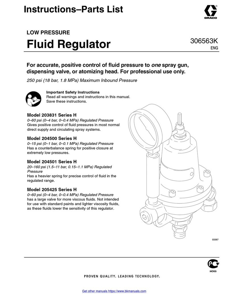
Graco H Series Operation manual
Graco
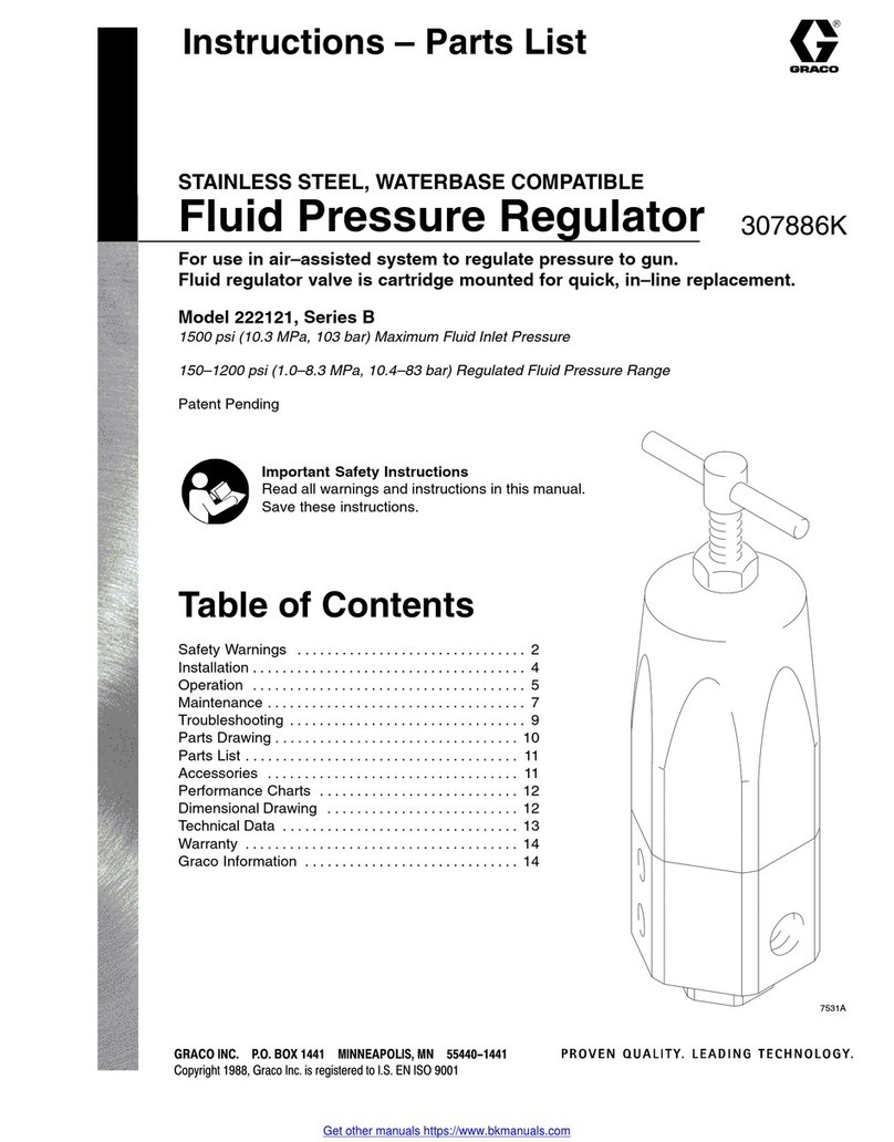
Graco Series B Operation manual
Graco
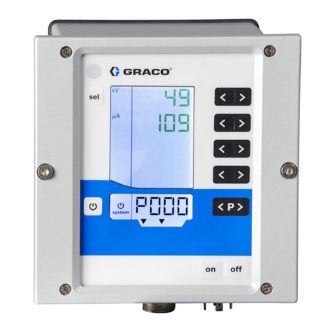
Graco Pro Xpc 24Y307 User manual
Graco
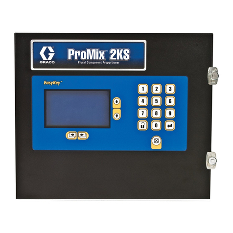
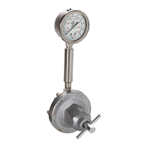
Graco ProMix 2KS Operating instructions
Graco
Graco 217314 Operation manual
Graco
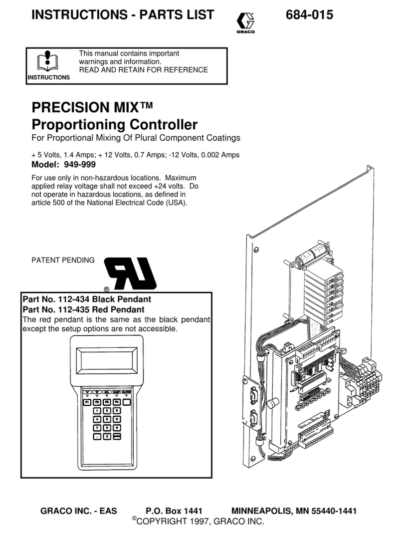
Graco PRECISION MIX 949-999 User manual

Graco
Graco ProBell 24Z221 Parts list manual
Graco
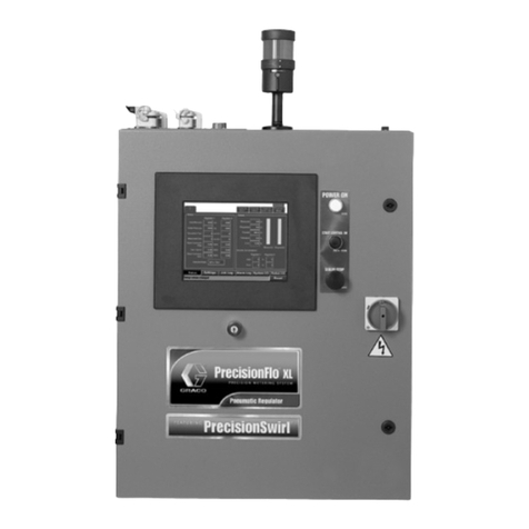
Graco PrecisionFlo XL User manual
Graco
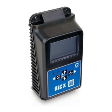
Graco 26A814 User manual
Graco
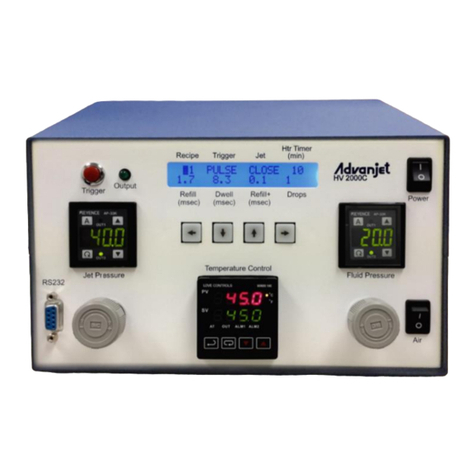
Graco Advanjet Diaphragm-Jet HV-2000 Manual instruction
Graco
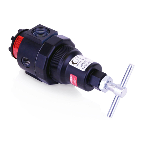
Graco 104266 User manual
Graco
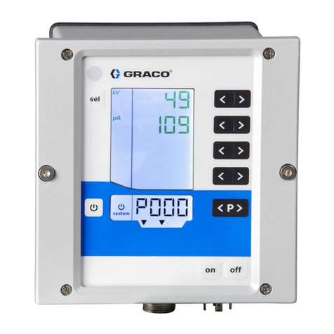
Graco ProBell Electrostatic Controller Parts list manual
Graco
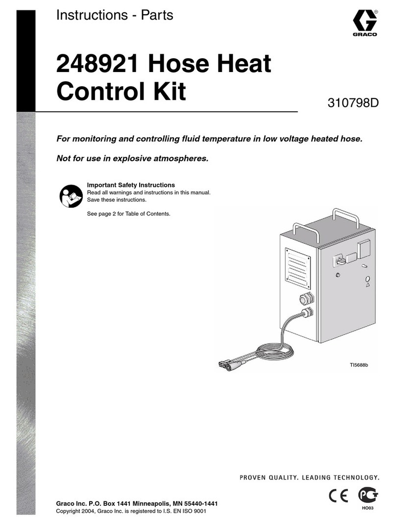
Graco 248921 310798D Parts list manual
Graco
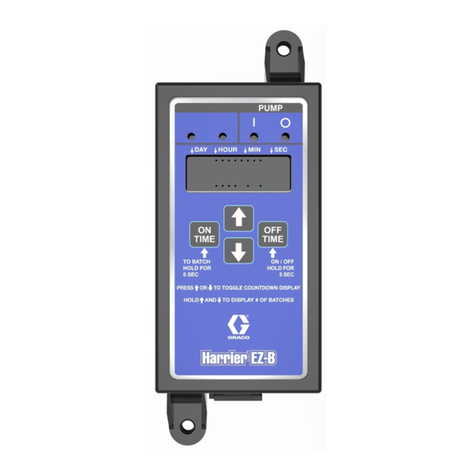
Graco Harrier EZ-Batch User manual
Graco
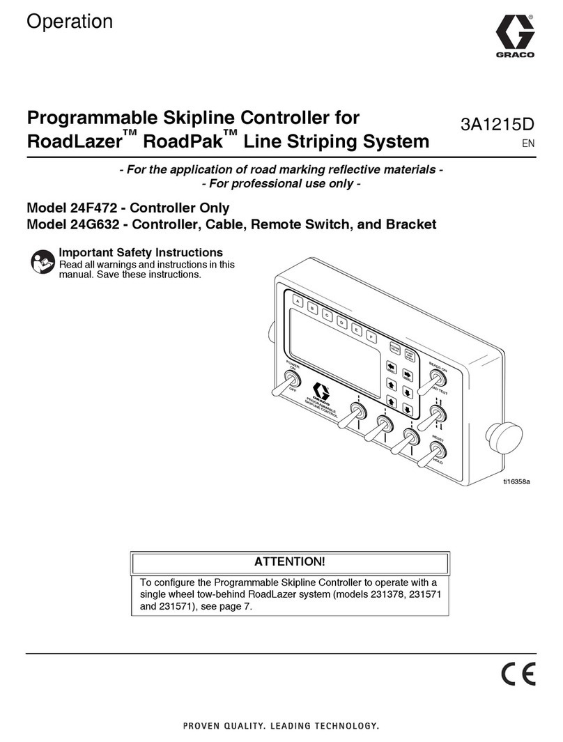
Graco 24F472 Instruction Manual
Graco
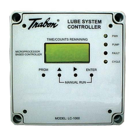
Graco Trabon LC-1000 User manual
Graco
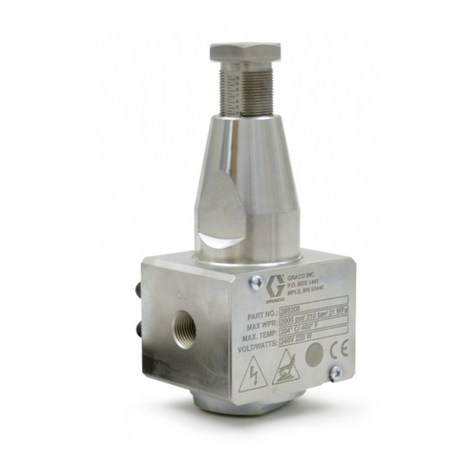
Graco 289208 Operation manual

Graco
Graco 114-459 Operation manual
Popular Controllers manuals by other brands

Digiplex
Digiplex DGP-848 Programming guide

YASKAWA
YASKAWA SGM series user manual

Sinope
Sinope Calypso RM3500ZB installation guide

Isimet
Isimet DLA Series Style 2 Installation, Operations, Start-up and Maintenance Instructions

LSIS
LSIS sv-ip5a user manual

Airflow
Airflow Uno hab Installation and operating instructions
