308-3859
Installation
KEY–Fig.
1 and 2
A
Ground Wire on Graco Electrically Conductive Air Hose
B
Graco Electrically Conductive Air Hose (T
urbine Air Hose),
See page 1
1 for part numbers
C
Atomizing Air Hose, 3/8 inch (9.5 mm) O.D.
D
Fan Air Hose, 3/8 inch (9.5 mm) O.D.
E
Cylinder Air Hose, 1/4 inch (6.4 mm) O.D.
F
Fluid Hose, 1/4–18.6 npsm gun fluid inlet
GT
o Fluid Supply
H
PRO 5500sc Spray Gun, P/N 236–683
J
Mounting Bracket for 1/2 inch (127 mm) rod, P/N 189–581
K
Solenoid V
alve, requires quick-exhaust port
M
Air Pressure Regulator
N
T
rue Earth Ground
P
24 V
olt Power Supply
, P/N 235–301
Q
4–20 mA Outputs
R
Full Feature ES Display Module, P/N 224–1
17
S
kV Only ES Display Module (battery operated), P/N 189–762
T
Fiber Optic Cable, P/N 224–680 to 224–686
U
Bulkhead, P/N 189–870
V
Fiber Optic Cable, P/N 224–670 to 224–676
W
Main Air Line
X
Bleed-type Master Air V
alve
YkV
Switch Air Hose, 1/4 inch (6.4 mm) O.D.,
plug the gun fitting if
it
is not used
Z
Air Pilot Fluid Regulator
, P/N 236–854
AA
Dump V
alve, P/N 236–853, requires installation of item FF
BB
Air Pilot Air Line, 1/4 inch (6.4 mm) O.D.
CC
Fluid Supply Line, 3/8 inch (9.5 mm) O.D.
DD
Dump T
rigger Air Line, 1/4 inch (6.4 mm) O.D.
EE
Fluid Return Line, 1/4 inch (6.4 mm) O.D.
FF
Fluid Recirculation Kit P/N 236–851, Includes fittings and fluid
tube
GG
PRO 5500sc Recirculating Spray Gun, P/N 236–684, includes
item FF
The turbine air supply must be interlocked with the spray booth
ventilation fans.
A maximum of two splices with a total of 108 feet (32.94 m) of
cable can be used. For the strongest light signals, use a mini
-
mum number of bulkhead splices.
*
See page 1
1 for a description of the manifold connections.
Installing the System
ELECTRIC
SHOCK HAZARD
Installing and servicing this equipment
requires access to parts which could
cause an electric shock or other serious
injury if the work is not performed properly
.
D
Do not install or service this equipment unless
you are trained and qualified.
D
Comply with all local, state, and national codes
for the installation of electrical apparatus in a
Class
I
, Group D Hazardous Location.
D
Comply with all applicable local, state, and
national fire, electrical, and other safety regula
-
tions.
WARNING
Fig. 1, page 8, shows a typical Model PRO 5500sc
system. Fig. 2 shows some possible system options.
Accessories are available from your Graco representa
-
tive. Refer to the Product Data Sheet for the gun,
Form No. 305–623.
For assistance in designing a system that is custom
-
ized for your application, contact your Graco represen
-
tative or Graco T
echnical Assistance (see back page).
Warning Signs
Mount
warning signs in the spray area where they can
easily be seen and read by all operators. An English
W
arning Sign is provided with the gun. Additional
English, French, German, and Spanish signs are avail
-
able at no charge.
Part No.
Description
180–060 W
arning Sign (English)
180–061 W
arning Sign (French)
180–062 W
arning Sign (German)
180–063 W
arning Sign (Spanish)
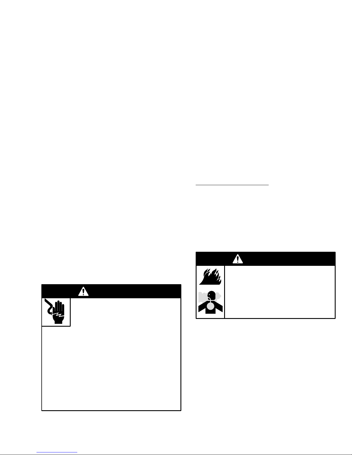
Ventilate the Spray Booth
FLAMMABLE
OR T
OXIC
V
APOR HAZARD
Provide fresh air ventilation to avoid the
buildup of flammable or toxic vapors. Do
not operate the gun unless ventilation
fans are operating.
WARNING
Electrically interlock the gun turbine air supply line with
the ventilators to prevent operation of the electrostatic
power supply unless ventilating fans are on.
Check and follow all local, state, and national codes
regarding air exhaust velocity requirements. High
velocity air exhaust will decrease the operating ef
fi-
ciency of the electrostatic system. The minimum
allowable air exhaust velocity is 60 feet/minute (19 lin
-
ear meters/minute).