manuals.online logo
Brands
  1. Home
  2. •
  3. Brands
  4. •
  5. Graff
  6. •
  7. Bathroom Fixture
  8. •
  9. Graff ME25 6101-LM41 User manual

Graff ME25 6101-LM41 User manual

IOG 2816.00 Rev. 1 February 2010
1
Dear Customer Estimado Cliente
Thank you for selecting our product. We are confident we can fully satisfy Muchas gracias por elegir nuestro producto. Estamos seguros que podemos
your expectations by offering you a wide range of technologically advanced satisfacer completamente sus expectativas ofreciéndole una amplia variedad
products which directly result from our many years of experience in faucet de productos tecnológicamente avanzados que resultan directamente de
and fitting production. muchos años de experiencia en grifos y su producción apropiada.
ENGLISH
~
ESPANOL
Model
Modelo ME25 6107-LM41 (Vessel)
Model
Modelo ME25 6106-LM41 (Vessel)
This faucet complies with NSF61/9, ASME/ANSI A112.18.1
and CSA B 125 Standards.
Este grifo se encuentra conforme con losestandares de NSF61/9,
de ASME/ANSI A112.18.1 y de CSA B 125. Installation Instructions  Instrucciones de Instalación
LAVATORY & VESSEL FAUCET
MEZCLADORA PARA OVALÍN Y LAVABO DE SOBREPONER
For care, use soft towel with soap and water only! Under no
circumstances should you use any chemicals. For faucets
with ORB (oil rubbed bronze) finish please be extra careful
not to damage, scuff or ruin the finish during the installation
and cleaning!
ATTENTION! ATENCIÓN!
Para el cuidado, utilice solamente una toalla suave con jabón y aqua!
Bajo ninguna circunstancia no use productos químicos. Con los grifos
de acabado ORB (bronce frotado con aceite) hay que tener un cuidado
especial para no dańar, arańar o destruir el acabado durante su
instalación o limpieza!
Model
Modelo ME25 6101-LM41 (Lav)
4-3/4" (120mm)
2-11/16" (68mm)
5-13/16" (147mm)
Ø1-3/4"
(Ø45mm)
Model
Modelo ME25 6102-LM41 (Lav)
4-1/8" (105mm)
1-15/16" (50mm)
5-1/16" (129mm)
Ø1-3/4"
(Ø45mm)
10-1/2" (267mm)
7-1/2" (190mm)
4-3/4" (120mm)
Ø1-3/4"
(Ø45mm)
10-1/2" (267mm)
7-1/2" (190mm)
6-1/2" (165mm)
Ø1-3/4"
(Ø45mm)
~
ESPANOL
IOG 2816.00 Rev. 1 February 2010
2
This faucet complies with NSF61/9, ASME/ANSI A112.18.1
and CSA B 125 Standards.
Este grifo se encuentra conforme con losestandares de NSF61/9,
de ASME/ANSI A112.18.1 y de CSA B 125. Installation Instructions  Instrucciones de Instalación
LAVATORY & VESSEL FAUCET
MEZCLADORA PARA OVALÍN Y LAVABO DE SOBREPONER
For easy installation of your
GRAFF faucet you will need:
to READ ALL the instructions completely
before beginning,
to READ ALL the warnings, care and
maintenance information.
To complete the project, you should:
gather the tools and all the parts you will
need,
prepare the mounting area,
mount the faucet,
connect the supply lines,
finally test and flush the faucet.
You should have the following tools:
adjustable wrench,
adjustable pliers,
hex key (included in the box),
®
Teflon tape.











Para la instalación fácil de su grifo
de la GRAFF usted necesitará:
LEER TODAS las instrucciones
completamente antes de comenzar,
LEER TODA la información sobre las
advertencias, cuidado y mantenimiento.
Para terminar el proyecto, usted debe:
recolectar las herramientas y todas las
piezas que usted necesitará,
prepare el área para el montaje,
monte el grifo,
conecte las líneas de fuente,
finalmente pruebe y limpie el grifo con un
chorro de agua.
Usted debe tener las herramientas
siguientes:
llave ajustable,
alicates acanalados,
llave hexagonal (incluido en la caja),
®
cinta adhesiva de Teflon .











ENGLISH
ENGLISH
~
ESPANOL
1
2
3
4
5
6
7
8
9
10
11
12
13
14
15
16
17
18
19
20
A
B
1
2
3
4
5
6
7
8
9
10
11
12
13
14
15
16
17
18
19
20
A
B
FAUCET BODY
AERATOR INSERT
SET SCREW
CARTRIDGE
NUT
CARTRIDGE COVER
LEVER BODY
BOLT
LEVER BAR
THREADED STUB PIPE
SUPPLY TUBE (2 PCS.)
LIFT-ROD KNOB
LIFT-ROD
POSITIONING INSERT
BASE
BASE WASHER
RUBBER WASHER
METAL WASHER
MOUNTING NUT
SUPPLY HOSE, 3/8” COMPRESSION,
LENGTH 17-11/16” (450mm) (2 PCS.)
7/64” (2.5mm) HEX KEY
SPECIAL KEY FOR THE AERATOR
CUERPO DE LA MEZCLADORA
INSERTO DEL AEREADOR
TORNILLO DE FIJACIÓN
MEZCLADOR
TUERCA
CUBIERTA DEL MEZCLADOR
CUERPO DEL PALANCA
PERNO
BARRA DE LA PALANCA
ROSCA DE LA UNIÓN
TUBO DE SUMINISTRO (2 PIEZAS)
PERILLA DE LA BARRA DE LEVANTAMIENTO
BARRA DE LEVANTAMIENTO
INSERTO DE COLOCACIÓN
BASE
ARANDELA DE LA BASE
ARANDELA DE CAUCHO
ARANDELA DE METAL
TUERCA DE MONTAJE
MANGUERA DE SUMINISTRO, 3/8" COMPRESIÓN,
LONGITUD DE 17-11/16" (450mm) (2 PIEZAS)
LLAVE ALLEN 7/64" (2,5mm)
LLAVE ESPECIAL PARA EL AEREADOR
See fig. 1.1, 1.2 Ver la figura 1.1, 1.2
Model
Modelo ME25 6108-LM41 (Vessel)
12-7/8" (327mm)
9-7/8" (250mm)
8-1/4" (210mm)
Ø1-3/4"
(Ø45mm)
ME25 6101-LM41 (Lav), ME25 6102-LM41 (Lav) ME25 6106-LM41 ME25 6107-LM41 (Vessel)
ME25 6108-LM41 (Vessel)
(Vessel),
IOG 2816.00 Rev. 1 February 2010
3
This faucet complies with NSF61/9, ASME/ANSI A112.18.1
and CSA B 125 Standards.
Este grifo se encuentra conforme con losestandares de NSF61/9,
de ASME/ANSI A112.18.1 y de CSA B 125. Installation Instructions  Instrucciones de Instalación
LAVATORY & VESSEL FAUCET
MEZCLADORA PARA OVALÍN Y LAVABO DE SOBREPONER
1.1 1.2
FLOW RATE INFORMATION
Maximum flow rate: 2.2 gpm (8.3 L/min) at 60 psi (4.1 bar)
INFORMACIÓN DE INTENSIDAD DE FLUJO
Flujo máximo: con 60 psi (4.1 bar)2.2 gpm (8.3 L/min)
FLOW RATE INFORMATION
Maximum flow rate: at 60 psi (4.1 bar)2.2 gpm (8.3 L/min
2.2 gpm (8.3 L/min)
INFORMACIÓN DE INTENSIDAD DE FLUJO
Flujo máximo: con 60 psi (4.1 bar)
20
3/8" COMPRESSION
3/8" COMPRESSION
14
11
13
10
15
16
17
18
19
A
1
21
2
3
B
6
7
5
4
8 9
20
3/8" COMPRESSION
3/8" COMPRESSION
14
11
15
16
17
18
19
A
1
2
3
B
10
6
7
5
4
8 9
~
ESPANOL
For Models 6101-LM41, 6102-LM41 (Lav) and 6106-LM41,
6107-LM41, 6108-LM41 (Vessel)
See fig. 2
1. Hand tighten the supply hoses (20) into the threaded ends of copper
lines (11). (With the spout facing towards you, screw the red labeled
hose into the left tube and the blue labeled hose into the right tube).
2. Note: For models 6101-LM41, 6102-LM41 (Lav Faucet) slide the
lift rod (13) down the hole on the back of the body (1). Have the lift
rod knob (12) that is already attached facing outwards. Models
6106-LM41, 6107-LM41, 6108-LM41 (Vessel Faucet) does not
use a lift rod.
3. Insert the rubber washer (16) into the undercut of the faucet base
(15). Make sure that the washer stays flat inside the undercut.
4. Insert both supply hoses (20), the lift rod (13) through the faucet
base (15) while having the washer side facing down (away from the
faucet). Place the faucet body (1) directly on top of the faucet base
(15) and make sure the rubber washer is facing down.
5. Insert both supply hoses (20), the lift rod (13), and the threaded stub
pipe (10) through the hole of designated install.
6. Slide the rubber washer (17) under the designated hole, with the
metal washer (18) underneath it, on the threaded stub pipe (10).
7. Hand tighten the mounting nut (19) to the bottom of the threaded
stub pipe (10). Adjust the spout to be in the right position, then
tighten the mounting nut (19) with an adjustable wrench.
For models 6101-LM41, 6102-LM41 continue on to page 5, for
installation of drain assembly.
For models 6106-LM41, 6107-LM41, 6108-LM41 see installation
instructions for required drain assembly.
Para los Modelos 6101-LM41, 6102-LM41 (Ovalín) y 6106-LM41,
6107-LM41, 6108-LM41 (Lavabo de sobreponer)
Ver la figura 2
1. Enrosque las mangueras de suministro (20) ajustando a mano al
extremos roscados los tubos (11). (Con el surtidor de la mezcladora
hacia usted, enrosque la manguera de etiqueta roja en el tubo
izquierdo y la de etiqueta azul en el tubo derecho).
2. Nota: Para los modelos 6101-LM41, 6102-LM41 (mezcladora para
ovalín) deslice la barra de levantamiento (13) por el orificio de la parte
posterior del cuerpo (1). Coloque la perilla de la barra de
levantamiento (12), que ya está instalada, hacia fuera. Los modelos
6106-LM41, 6107-LM41, 6108-LM41 (mezcladora para lavabo de
sobreponer) no usa barra de levantamiento.
3. Inserte la arandela de caucho (16) en el rebaje de la base de la mezcladora (15). Asegúrese de que la arandela quede al ras dentro del rebaje.
4. Inserte las dos mangueras de suministro (20), la barra levantadora (13) por la base de la mezcladora (15) con el lado de la arandela hacia abajo
(lejos de la mezcladora). Coloque el cuerpo de la mezcladora (1) directamente sobre la base de la mezcladora (15) y asegúrese de que la arandela
de caucho se encuentre boca abajo.
5. Inserte las dos mangueras de suministro (20), la barra de levantamiento (13) y la rosca de la unión (10) a través del orificio de instalación
designado.
6. Deslice la arandela de caucho (17) abajo del orificio designado, con la arandela de metal (18) debajo, en la rosca de la unión (10).
7. Enrosque la tuerca de montaje (19) a mano hasta la parte superior de la rosca de la unión (10). Ajuste el surtidor hasta lograr la posición correcta,
después apriete la tuerca de montaje (19) con una llave inglesa.
Para los modelos 6101-LM41, 6102-LM41 vaya a la página 5 para continuar con la instalación del ensamble de drenaje.
Para los modelos 6106-LM41, 6107-LM41, 6108-LM41 vea las instructiones de instalación para el montaje de drenaje necesario.
ENGLISH
1
FAUCET INSTALLATION  INSTALACIÓN DE LA MEZCLADORA
2
IOG 2816.00 Rev. 1 February 2010
4
This faucet complies with NSF61/9, ASME/ANSI A112.18.1
and CSA B 125 Standards.
Este grifo se encuentra conforme con losestandares de NSF61/9,
de ASME/ANSI A112.18.1 y de CSA B 125. Installation Instructions  Instrucciones de Instalación
LAVATORY & VESSEL FAUCET
MEZCLADORA PARA OVALÍN Y LAVABO DE SOBREPONER
15
12
1
16
17
13
18
19
3/8" COMPRESSION
3/8" COMPRESSION
20
11
10
MAX. 1-3/4"
(MAX. 45mm)
Ø1-1/4"
(Ø32mm)
ENGLISH
ENGLISH
~
ESPANOL
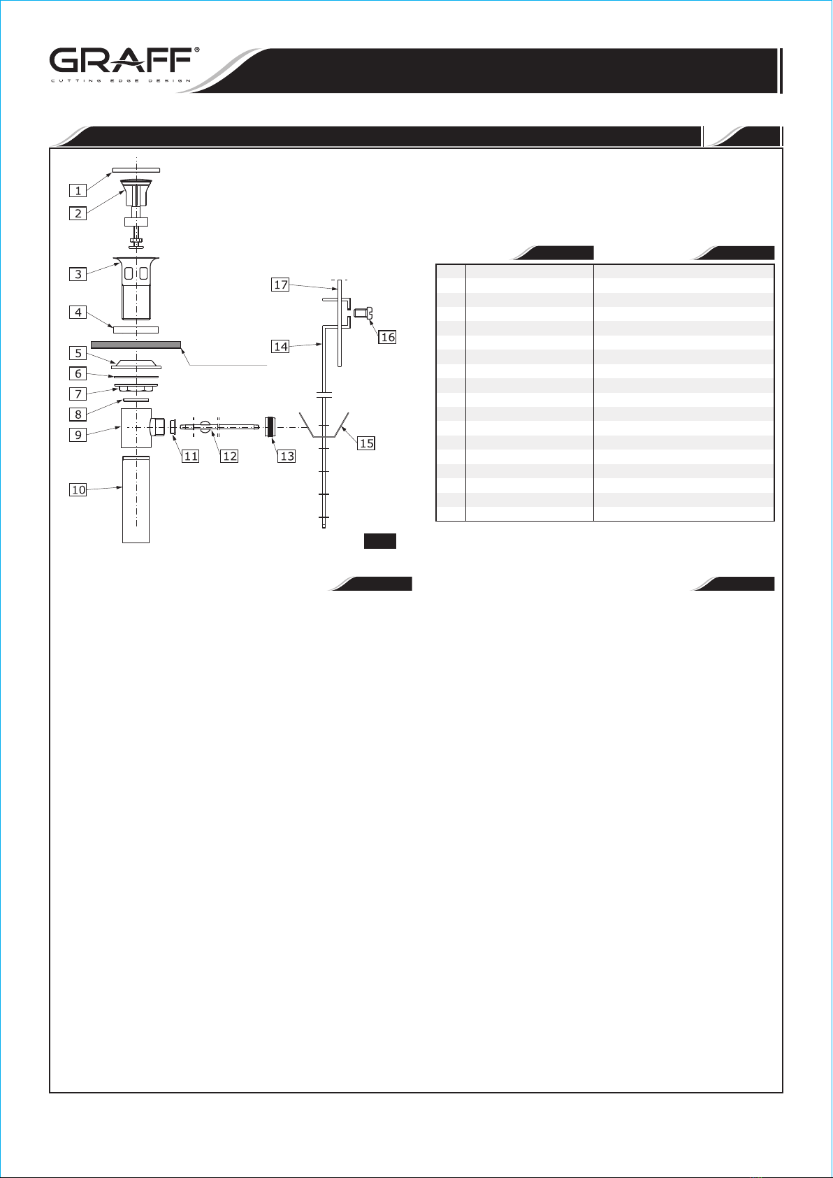
1. Dismantle the drain assembly to the parts shown on fig. 3.
2. Remove the protective cap (1) and discard. Please recycle the
protective cap (1). Insert drain collar (3) through collar gasket (4)
and into the drain hole of the sink. (Note: If installer uses another
installation method using other than the supplied collar gasket
(4), please check with the sink manufacture because it may
void the warranty. Do not use silicone with Graff parts).
3. From beneath the sink, slide the under-bowl rubber gasket (5) up the
threaded section of the drain collar (3). Make sure the flat side is down
and the tapered side up. Slide the washer (6) up the threaded section
of the drain collar (3) up to the under-bowl rubber gasket (5). Screw
the flange nut (7), firmly but do not over tighten, on the threaded
section of the drain collar (3). (Note: Make sure the horizontal hole
on the drain body (9) is the same plane as the lift rod (17)).
4. Insert drain plug (2) into drain collar (3) and line up the hole at the
bottom of the drain plug (2) with the horizontal hole on the drain collar
(9). (Note: The plastic hole at the bottom of the drain plug (2)
adjusts by simply turning it. This will adjust the height of the
drain plug (2) top). Insert sealing washer (11) into the horizontal
hole of the drain body (9). Insert the ball rod (12), short side, through
the sealing washer (11) and into the hole of the drain body (9). Slide
the ball rod nut (13) over the ball rod (12) and screw it on the
horizontal hole of the drain body (9).
®
5. Add Teflon tape to the threaded side of the discharge pipe (10) and
screw into the bottom of the drain body (9).
6. Lift the drain plug (2) by moving the ball rod (12) into a down position.
Slide the clip (15) up the adjustment plate (14). Insert the ball rod
(12) through one side of the clip (15), then a hole of choice on the
adjustment plate (14), and the other hole of the clip (15). Keep the
ball rod (12) in the down position, slide the adjustment plate up the
lower part of the lift rod (17). Still holding the ball rod in a down
position, drain plug is up, and tighten the screw (16).
1. Desmonte el ensamble del drenaje hasta tener las partes que se
muestran en la Figura 3.
2. Quite la tapa protectora (1) y deséchela. Por favor recicle la tapa
protectora (1). Inserte el collar de drenaje (3) a través del empaque
del collar (4) y en el orificio de drenaje del lavabo. (Nota: Si el
instalador usa otro método de instalación usando un empaque
que no sea el proporcionado por nosotros (4), por favor
consulte con el fabricante del lavabo, ya que esto puede anular
la garantía. No use silicón con las piezas de Graff).
3. Desde la parte inferior del lavabo, deslice el empaque de caucho
inferior (5) hacia arriba por la sección roscada del collar del drenaje
(3). Asegúrese de que el lado plano se encuentre hacia abajo y el lado
cónico hacia arriba. Deslice la arandela (6) hacia arriba por la sección
roscada del collar del drenaje (3) hasta llegar al empaque de caucho
inferior (5). Enrosque la tuerca-brida (7), con firmeza pero sin apretar
excesivamente, en la sección roscada del collar de drenaje (3). (Nota:
Asegúrese de que el orificio horizontal del cuerpo del drenaje
(9) esté en el mismo plano que la barra de levantamiento (17)).
4. Inserte el tapón del drenaje (2) en el collar del drenaje (3) y alinee el
orificio situado en la parte inferior del tapón (2) con el orificio
horizontal que se encuentra en el collar del drenaje (9). (Nota: El
orificio de plástico situado en la parte inferior del tapón del
drenaje (2) se ajusta simplemente girándolo. Esto ajustará la
altura del tapón del drenaje (2)). Inserte la arandela selladora
(11) en el orificio horizontal del cuerpo del drenaje (9). Inserte el lado
corto de la barra de bola (12) a través de la arandela selladora (11) y
en el orificio del cuerpo del drenaje (9). Deslice la tuerca de la barra de
bola (13) sobre la barra (12) y enrósquela en el orificio horizontal del
cuerpo del drenaje (9).
®
5. Coloque cinta de Teflón en el lado roscado del tubo de desagüe (10) y
enrósquelo en la parte inferior del cuerpo del drenaje (9).
6. Levante el tapón del drenaje (2) bajando la barra de bola (12). Deslice
el sujetador (15) hasta la placa de ajuste (14). Inserte la barra de
bola (12) a través de un lado del sujetador (15), después por un
orificio de su elección de la placa de ajuste (14) y pásela por el otro
orificio del sujetador (15). Mantenga abajo la barra de bola (12),
deslice la placa de ajuste por la parte inferior de la barra de
levantamiento (17). Mientras mantiene abajo la barra de bola, con el
tapón del drenaje arriba, apriete el tornillo (16).
2
DRAIN ASSEMBLY INSTALLATION  INSTALACIÓN DEL DRENAJE
3
1
2
3
4
5
6
7
8
9
10
11
12
13
14
15
16
17
1
2
3
4
5
6
7
8
9
10
11
12
13
14
15
16
17
PROTECTIVE CAP
DRAIN PLUG
DRAIN COLLAR
COLLAR GASKET
UNDER-BOWL GASKET
WASHER
FLANGED NUT
WASHER
DRAIN BODY
DISCHARGE PIPE
SEALING WASHER
BALL ROD
BALL ROD NUT
ADJUSTMENT PLATE
CLIP
SCREW
LIFT ROD FROM
FAUCET
TAPA PROTECTORA
TAPÓN DE DRENAJE
COLLAR DE DRENAJE
EMPAQUE DEL COLLAR
EMPAQUE INFERIOR
ARANDELA DE MONTAJE
TUERCA-BRIDA
ARANDELA DE TUBO
CUERPO DE DRENAJE
TUBO DE DESAGÜE
ARANDELA SELLADORA
BARRA DE BOLA
TUERCA DE LA BARRA DE BOLA
PLACA DE AJUSTE
SUJETADOR
TORNILLO
BARRA DE LEVANTAMIENTO DE LA
MEZCLADORA
~
ESPANOL
SINK
LAVAMANOS
IOG 2816.00 Rev. 1 February 2010
5
This faucet complies with NSF61/9, ASME/ANSI A112.18.1
and CSA B 125 Standards.
Este grifo se encuentra conforme con losestandares de NSF61/9,
de ASME/ANSI A112.18.1 y de CSA B 125. Installation Instructions  Instrucciones de Instalación
LAVATORY & VESSEL FAUCET
MEZCLADORA PARA OVALÍN Y LAVABO DE SOBREPONER
ENGLISH
~
ESPANOL
5
CARE AND MAINTENANCE  CUIDADO Y MANTENIMIENTO
ENGLISH
~
ESPANOL
WARRANTY  GARANTÍA
All dimensions and drawings are for reference only. For details, please refer to actual products.
Todas las dimensiones y dibujos sirven únicamente de referencia. Para consultar detalles, ver los productos.
Your Graff faucet is designed and engineered in accordance with the
highest quality and performance standards. Be sure not to damage the
finish during installation. Care should be given to the cleaning of this
product. Although its finish is extremely durable, it can be damaged by
harsh abrasives or polish. Never use abrasive cleaners, acids,
solvents, etc. to clean any Graff product. To clean, simply wipe
gently with a damp cloth and blot dry with a soft towel.
Warranty conditions and warranty registration card are outlined on a
separate sheet.
Su grifo de la Graff esta diseńado y dirigido acuerdo con los estándares de
funcionamiento y calidad más altos. Este seguro no dańar las terminaciones
del grifo durante la instalación. Cuide el producto manteniendolo siempre
limpio. Aunque su acabado es extremadamente durable, puede ser dańado
por los abrasivos o pulientes ásperos. Nunca utilice limpiadores
abrasivos, ácidos, solventes, el etc. para limpiar cualquier producto
de la Graff. Para limpiar, simplemente use un pańo húmedo y seque
con una toalla suave.
Las condiciones de la garantía y la tarjeta del registro de la garantía se
encuentran en una pagina separada.
3
4
The water flow is opened and regulated by pushing the vertical lever
downwards. The temperature is increased by turning the lever to the left
and decreased by turning it to the right. Turning it all the way to the left
gives a flow of only hot water, all the way to the right gives only cold
water.
It is recommended that every 3-6 months (depending on water quality)
you remove the aerator (item 2, fig. 1.1, 1.2) from the faucet spout in
order to remove any impurities. For this purpose, use the special key (B)
supplied.
See fig. 1.1, 1.2
1. Remove aerator insert (2) (use the special key (B) supplied) and turn
faucet handle to the full on mixed position.
2. Turn on hot and cold water supply valves and flush water lines for 15
1)
seconds .
3. Check all connections at arrows for leaks. Re-tighten if necessary, but
do not overtighten.
4. Replace aerator insert (2). Use the special key (B).
1) IMPORTANT: This flushes away any debris that could cause damage to
internal parts.
La aperture de la salida de agua y la regulación de su gasto sucede a causa
de bajar la palanca en la superficie vertical. El aumento de la temperature del
agua sucede al tornar la palanca a la izquierda, y la reducción al tornar la
palanca a la derecha. La posición extrema izquierda del mango de la salida
sólo al agua caliente, la extrema derecha la salida sólo del agua fría.
Una vez a 3-6 meses (dependiendo de la calidad del agua) se recomienda
quitar el aereador (pos. 2, la fig. 1.1, 1.2) del caño de la mezcladora con el fin
de limpiarlo de todo tipo de ensuciamiento. Para eso use una llave especial
(B) anexa al juego.
Ver la figura 1.1, 1.2
1. Retire el inserto del aereador (2) (use una llave especial (B) anexa al
juego) y gire el mango del grifo a la posición de mezclado completo.
2. Abra las válvulas de suministro de agua fría y caliente y enjuague las
1)
lineas de agua por 15 seg.
3. Chequee todas las conecciones para ver si hjay fuga de agua.
Reajuste si es necesario, pero no ajuste demasiado.
4. Coloque el inserto del aereador (2). Ajuste solo con la llave especial (B).
1) IMPORTANTE: Esto limpia los residuos que podrían causar daño a las
piezas internas con un chorro de agua.
~
ESPANOL
~
ESPANOL
ENGLISH
ENGLISH
OPERATING INSTRUCTIONS  LA DESCRIPCIÓN DEL FUNCIONAMIENTO
AFTER INSTALLATION BEFORE USE  DESPUES DE LA INSTALACIÓN Y ANTES DEL USO
IOG 2816.00 Rev. 1 February 2010
6
This faucet complies with NSF61/9, ASME/ANSI A112.18.1
and CSA B 125 Standards.
Este grifo se encuentra conforme con losestandares de NSF61/9,
de ASME/ANSI A112.18.1 y de CSA B 125. Installation Instructions  Instrucciones de Instalación
LAVATORY & VESSEL FAUCET
MEZCLADORA PARA OVALÍN Y LAVABO DE SOBREPONER

This manual suits for next models

5

Other Graff Bathroom Fixture manuals

Graff C14U-WS Series User manual

Graff

Graff C14U-WS Series User manual

Graff E-11462-C19L Operator's manual

Graff

Graff E-11462-C19L Operator's manual

Graff E-11900-LM69 Operator's manual

Graff

Graff E-11900-LM69 Operator's manual

Graff MUS92 User manual

Graff

Graff MUS92 User manual

Graff Cameo E-11905-LM69 User manual

Graff

Graff Cameo E-11905-LM69 User manual

Graff Canterbury 3800-C2 User manual

Graff

Graff Canterbury 3800-C2 User manual

Graff GX-6170-LM3F User manual

Graff

Graff GX-6170-LM3F User manual

Graff EX-11170 Operator's manual

Graff

Graff EX-11170 Operator's manual

Graff E-9960-T Operator's manual

Graff

Graff E-9960-T Operator's manual

Graff Immersion 2357-LM31N-T User manual

Graff

Graff Immersion 2357-LM31N-T User manual

Graff 8711 User manual

Graff

Graff 8711 User manual

Graff Camden E-8509 Operator's manual

Graff

Graff Camden E-8509 Operator's manual

Graff Aqua-Sense Operator's manual

Graff

Graff Aqua-Sense Operator's manual

Graff G-8220 User manual

Graff

Graff G-8220 User manual

Graff Cameo E-11961-LM69 Operator's manual

Graff

Graff Cameo E-11961-LM69 Operator's manual

Graff E-11610-C20B Operator's manual

Graff

Graff E-11610-C20B Operator's manual

Graff Terra 5557800 Operator's manual

Graff

Graff Terra 5557800 Operator's manual

Graff HARLEY E-11469-C19B Operator's manual

Graff

Graff HARLEY E-11469-C19B Operator's manual

Graff E-11557 L1 Series Operator's manual

Graff

Graff E-11557 L1 Series Operator's manual

Graff G-8231 User manual

Graff

Graff G-8231 User manual

Graff TERRA G-6156-LM46B T Series User manual

Graff

Graff TERRA G-6156-LM46B T Series User manual

Graff AMETIS G-8760 User manual

Graff

Graff AMETIS G-8760 User manual

Graff Harley E-8714-HS2 Operator's manual

Graff

Graff Harley E-8714-HS2 Operator's manual

Graff SOLAR Operator's manual

Graff

Graff SOLAR Operator's manual

Popular Bathroom Fixture manuals by other brands

Sloan TruFlush TRF 156-1.6 installation instructions

Sloan

Sloan TruFlush TRF 156-1.6 installation instructions

Brizo JASON WU FOR BRIZO 695060 Series manual

Brizo

Brizo JASON WU FOR BRIZO 695060 Series manual

Allen + Roth 1605VA-48-201-925 manual

Allen + Roth

Allen + Roth 1605VA-48-201-925 manual

Spectrum Brands Pfister Courant F-048-CO Quick installation guide

Spectrum Brands

Spectrum Brands Pfister Courant F-048-CO Quick installation guide

Kohler BELAY K-156T-LCP installation instructions

Kohler

Kohler BELAY K-156T-LCP installation instructions

Kohler K-922 installation guide

Kohler

Kohler K-922 installation guide

Glacier bay HD910-X1110H Use and care guide

Glacier bay

Glacier bay HD910-X1110H Use and care guide

Ideal-Standard iLife QUADRANT T4935EO Manual for Use, Installation and Maintenance

Ideal-Standard

Ideal-Standard iLife QUADRANT T4935EO Manual for Use, Installation and Maintenance

GoodHome boxwood 5059340124001 manual

GoodHome

GoodHome boxwood 5059340124001 manual

Insignia INS8719 installation manual

Insignia

Insignia INS8719 installation manual

KWC FAID0007 Installation and operating instructions

KWC

KWC FAID0007 Installation and operating instructions

Burlington R8 CHR quick start guide

Burlington

Burlington R8 CHR quick start guide

HydroTherm B Series quick start guide

HydroTherm

HydroTherm B Series quick start guide

American Standard BELFORD 8473502.075 General description

American Standard

American Standard BELFORD 8473502.075 General description

Ridder Assistent A0130201 instructions

Ridder

Ridder Assistent A0130201 instructions

Nobili Seven SE124119/1 quick start guide

Nobili

Nobili Seven SE124119/1 quick start guide

Sloan MH-3050 Installation and operation instruction

Sloan

Sloan MH-3050 Installation and operation instruction

Saniverre ATEA MATILDE DK11 manual

Saniverre

Saniverre ATEA MATILDE DK11 manual

manuals.online logo
manuals.online logoBrands
  • About & Mission
  • Contact us
  • Privacy Policy
  • Terms and Conditions

Copyright 2025 Manuals.Online. All Rights Reserved.