GB D
INSTALLATION OF THE SPOUT – see figs. 3.1 and 3.2
1. Place the spout (1) over the spout connection (B), taking care not to damage the o-rings (OR). Push the
spout(1) until the escutcheon touchesthe finishing wall.
2. Putthe spout (1) in thecorrect position and fasten it with a bolt (4) using a hex key (K1) – see fig. 3.2.
MONTAGE DERAUSLAUFGARNITUR– sieheAbb. 3.1und 3.2
1. Die Auslaufgarnitur (1) auf das Verbindungsstück der Auslaufgarnitur (B)aufschieben. Beachten Sie,
dass die O-Ringe (OR) nicht beschädigt werden können. DieAuslaufgarnitur (1) heranschieben, bis die
RosettederAuslaufgarnitur dieAusbauwand berührt.
2. Die Auslaufgarnitur (1) richtig positionieren und mit einer Schraube (4) mit Hilfe eines
Innensechskantschlüssels(K1) anschrauben – siehAbb.3.2.
F
MONTAGE DU ROBINET – voir les schémas 3.1 et 3.2
1. Placer le robinet (1) sur le raccordement du robinet (B), en prenant soin de ne pas endommager les
joints toriques (OR). Pousserlerobinet (1) jusqu'à ce que la rosace soit en contact avec la surface de la
paroide finition.
2. Positionner correctement le robinet (1) et le fixer a l'aide de vis (4)en utilisant le joint clé Allen (K1) –voir
le schéma3.2.
4
F
GB D
DESCRIPTIONDU FONCTIONNEMENT
L'ouverture de l'eau et la régulation du débit s'effectuent en levant le levier de commande (angle maxi.
25).Son abaissement permet de fermer l'arrivée d'eau.
L'augmentation de la température de l'eau s'effectue en tournant la poignée de commande vers la
gauche et la diminution de la température en tournant la poignée vers la droite. La poignée de
commande positionnée complètement à gauche permet de sélectionner uniquement l'eau chaude,
complètementà droite uniquement l'eau froide.
OPERATIONAL DESCRIPTION
Opening the water outflow, as well as obtaining a steady regulation of water discharge, is achieved
by pushing the lever up (by max. 25). Lowering the handle stops water discharge.
The water temperature increases when the handle is turned left, and decreases when the handle is
turned right. When the handle is in the extreme left position only hot water flows, and in the extreme
right position only cold water flows.
FUNKTIONSBESCHREIBUNG
Das Öffnen des Wasserauslaufs und die stufenlose Einstellung des auslaufenden Wassers erfolgen durch
Verstellen desHebels nach oben(ummax. 25).DieSenkungdesGriffesschließtdenWasserstrom ab.
Durch Drehen des Griffs nach links wird die Wassertemperatur erhöht; durch Drehen des Griffs nach
rechts wird die Wassertemperatur gesenkt. Die linke Endstellung des Griffs verursacht den Austritt von
ausschließlichheißem Wasser, die rechte Endstellungvon ausschließlich kaltem Wasser.
IOG 5703.31
Rev. 1 February 2020
MAINTENANCE
Clean water guarantees that a mixer equipped with ceramic flow regulators will work correctly, i.e. th
water should not contain any impurities such as sand, boiler scale etc. Because of this, the pipe system
should be equipped with sieve filters or, if there is no such possibility, with individual cut-off valves with
filtersdesigned for such units.
In the event of increased steering resistance, greater pressure should not be exerted on the handle, as
this may cause damage to the flow regulator. In such a situation, the regulator should be removed and
cleanedof the dirt and impuritieswhich have accumulated on it.
Theseals should be maintained withvaseline or silicon oil.
Cleaningthe outer coating:
dirt or stains on the external surfaces of the mixer resulting from scale deposits should be removed by
washingthe unit with soapy water only.Scale deposits should be dissolved with vinegar then the surface
rinsedwith clean water and rubbed dry with a soft cloth,
under no circumstances should the surface of the mixer be cleaned with coarse cloths or cleaning
agentscontaining abrasive materials or acids,
plastic or lacquered parts must not be cleaned with chemicals containing alcohol, disinfectants or
solvents.
WARTUNG
Eine Garantie für richtige Funktion von Batterien mit keramischen Durchflussregler ist sauberes
Wasser, dass heißt Wasser ohne solche Verunreinigungen, wie: Sand, Kesselstein, usw. Deswegen
wird die Ausrüstung der Wasserleitungsanlage mit Gitterfilter gefordert, und wenn solche Filter nicht
vorhandensind, soll es möglich sein,die für Batterien bestimmteAbsperrventile mit Filter zu montieren.
Bei vergrößertem Einstellungswiderstand soll man auf den Heben keinen größeren Druck ausüben, da
es eine Beschädigung des Durchflussreglers verursachen kann. Wenn es so ist, soll man den Regler
ausmontierenund die auf dem Reglergesammelten Verunreinigungenentfernen.
DieDichtungen sollen mit Vaselin oder Silikonöl gewartet werden.
Reinigungder äußeren Oberflächen:
Den Schmutz oder die Flecke, entstanden infolge von Steinablagerungen auf den äußeren
Batterieoberflächen, durchAbspülen mit Seifewasser entfernen, den Stein mit Essig lösen, danach die
Oberflächemit sauberem Wasserabspülen und mit weichem Lappen trocknen.
Auf keinem Fall die Batterieoberfläche mit rauen Lappen oder mit scheuermittel- oder säurehaltigen
Reinigungsmittelnreinigen
Für die Reinigung der Kunststoffteile oder lackierten Teile kann man keine alkoholhaltige Mitteln,
Desinfektions-oder Lösungsmitteln verwenden.
GB D
E
MONTAJE DELCAÑO – ver las figs. 3.1 y 3.2
1. Meta el caño (1) en el conector del caño(B), con cuidado para no dañar juntas tóricas (OR). Apriete el
caño(1) hastaque la roseta del caño toque la superficie de la pared de acabado.
2. Coloque el caño (1) en la posición adecuada y sujétela mediante el tornillo (4) usando la llave allén
adjunta(K1) – ver la fig. 3.2.
IT
MONTAGGIO DELLABOCCA – vedi fig. 3.1 i 3.2
1. Infilala bocca (1) sul connettore della bocca(B),facendoattenzione a non danneggiare leprotezioni tipo
o-ring (OR). Accosta la bocca (1) fino a quando il rosone della bocca sia in contatto con la superficie
dellaparete di finitura.
2. Colloca la bocca(1) in posizione corretta e fissala con la vite (4) usando la chiave a brugola fornita (K1)-
vedifig. 3.2.
RUS
– 3.1 3.2
1. (1) (B),
(OR). (1),
2. (1) (4)
(K1) - 3.2.
PL
MONT WYLEWKI– zob. rys. 3.1 i 3.2
1. (1) na wylewki (B), by nie typu (OR). (1)do momentu, rozeta wylewki zetknie z
2. Ustaw (1) we i (4) kluczykiemimbusowym (K1) zob. rys. 3.2.
E
DESCRIPCIÓN DE FUNCIONAMIENTO
La apertura de la salida del agua y el ajuste fluido de la misma ocurre al tirar el mango hacia arriba
(ángulo máx. de 25). Bajar el mango causa el cierre de la salida del agua.
Al girar el mango a la izquierda aumentamos la temperatura del agua, al girarlo a la derecha
disminuimos la temperatura. La posición extrema izquierda causa sólo la salida del agua caliente, la
extremaderecha – sólo la salidadel agua fría.
IT
DESCRIZIONEDEL FUNZIONAMENTO
L'apertura dell'uscita dell'acqua e la regolazione scorrevole della sua erogazione avviene tramite il
posizionamento della leva in alto (max di un angolo di 25). L'abbassamento della maniglia provoca la
chiusuradell'uscita dell'acqua.
L'aumento della temperatura dell'acqua avviene tramite la rotazione della maniglia a sinistra, mentre la
diminuzione tramite la rotazione della maniglia a destra. La posizione della maniglia estremamente a
sinistra provoca la fuoriuscita solamente dell'acqua calda, estremamente a destra – la fuoriuscita
solamentedell'acqua fredda.
RUS
25).
-
-
PL
OPIS
Otwarcie wody oraz wydatku w wyniku wychylenia do (o max. 25). Opuszczenie uchwytu wody.
temperatury wody przez uchwytu w lewo, a przez uchwytu w prawo. lewe uchwytu tylko wody prawe
tylkowody
GB D F RUSE IT PL
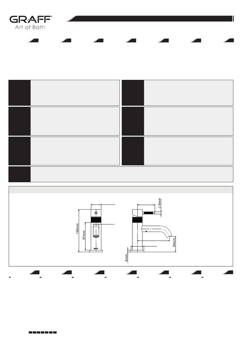
Instructions for assembly and use • Montage- und Gebrauchsanweisung • Notice technique montage et utilisation • c • Instrucción de Montaje y Servicio • Manuale di Montaggio e Uso • Instr ugi
BATERIAUMYWALKOWANA CIENNA(PODTYNKOWA)
WANDWASCHBECKEN-BATTERIE(UNTERPUTZ) ROBINETTERIEDELAVABOMURAL(ENCASTREE)
( )
GRIFERÍADELAVABO PARAPARED (BAJOENLUCIDO) BATTERIALAVABOAMURO(SOTTO L'INTONACO)
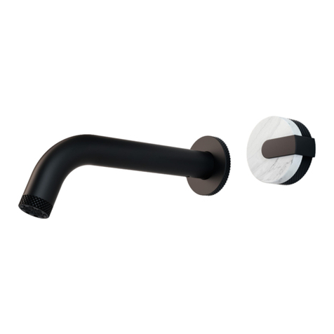
WALL-MOUNTMIXER(CONCEALED)
