manuals.online logo
Brands
  1. Home
  2. •
  3. Brands
  4. •
  5. Graff
  6. •
  7. Plumbing Product
  8. •
  9. Graff G-6950-LM48B User manual

Graff G-6950-LM48B User manual

2881.10GOI 1
Dear Customer Estimado Cliente
Thank you for selecting our product. We are confident we can fully satisfy Muchas gracias por elegir nuestro producto. Estamos seguros que podemos
your expectations by offering you a wide range of technologically advanced satisfacer completamente sus expectativas ofreciéndole una amplia variedad
products which directly result from our many years of experience in faucet de productos tecnológicamente avanzados que resultan directamente de
and fitting production. muchos años de experiencia en grifos y su producción apropiada.
ENGLISH
~
ESPANOL
This faucet complies with NSF61/9, ASME/ANSI A112.18.1
and CSA B 125 Standards.
Este grifo se encuentra conforme con losestandares de NSF61/9,
de ASME/ANSI A112.18.1 y de CSA B 125. Installation Instructions Instrucciones de Instalación
BATH FAUCET, 3-hole type
GRIFO PARA BAÑO, diseño de 3 agujeros
Model
Modelo G-6950-LM48B
~
ESPANOL
For easy installation of your
GRAFF faucet you will need:
to READ ALL the instructions
completely before beginning,
to READ ALL the warnings, care and
maintenance information.
To complete the project, you
should:
gather the tools and all the parts
you will need,
prepare the mounting area,
mount the faucet,
finally test and flush the faucet.
You should have the following
tools:
hex key (included in the box).







Para la instalación fácil de su grifo
de la GRAFF usted necesitará:
LEER TODAS las instrucciones
completamente antes de comenzar,
LEER TODA la información sobre las
advertencias, cuidado y
mantenimiento.
Para terminar el proyecto, usted
debe:
recolectar las herramientas y todas
las piezas que usted necesitará,
prepare el área para el montaje,
monte el grifo,
finalmente pruebe y limpie el grifo
con un chorro de agua.
Usted debe tener las herramientas
siguientes:
llave hexagonal (incluido en la caja).







ENGLISH
For care, use soft towel with soap and water only! Under no
circumstances should you use any chemicals.
ATTENTION! ATENCIÓN! Para el cuidado, utilice solamente una toalla suave con jabón
y aqua! Bajo ninguna circunstancia no use productos químicos.
Rev.1 May 2017
ENGLISH
~
ESPANOL
1
2
3
4
5
6
7
8
9
10
11
12
13
14
15
16
K1
K2
SPOUT BODY
HANDLE
HANDLE BODY
HANDLE BASE
SPOUT BASE
HEAD SPINDLE ELONGATION
SPOUT KNOB
AERATOR
HANDLE KNOB
SCREW
O-RING 48,2X3
SPECIAL KEY FOR THE AERATOR
2MM HEX KEY
CUERPO DEL CAÑO
PALANCA
CUERPO DE LA PALANCA
ZÓCALO DE LA PALANCA
BASE DEL CAÑO
EXTENSIÓN DEL HUSO DE LA CABEZA
MANIVELA DEL CAÑO
AEREADOR
MANIVELA DEL PALANCA
TORNILLO
JUNTA TÓRICA 48,2X3
LLAVE ESPECIAL PARA EL AEREADOR
LLAVE ALLEN 2MM
2-5/8"
68mm
7-7/8"
200mm
3-3/4"
96mm
7-1/8"
182mm
3-3/8"
86mm
5-3/8"
137mm
2-3/8"
60mm
O2-1/8"
55mm
O
2-1/8"
55mm
O
3/8"
10mm
SCREW TORNILLO
SLEEVE REJILLA
O-RING 8X3 JUNTA TÓRICA 8X3
SCREW TORNILLO
SCREW TORNILLO
K3 2,5MM HEX KEY LLAVE ALLEN 2,5MM
2
1
This faucet complies with NSF61/9, ASME/ANSI A112.18.1
and CSA B 125 Standards.
Este grifo se encuentra conforme con losestandares de NSF61/9,
de ASME/ANSI A112.18.1 y de CSA B 125. Installation Instructions Instrucciones de Instalación
BATH FAUCET, 3-hole type
GRIFO PARA BAÑO, diseño de 3 agujeros
1
2
4
11
13
12
3
14
5
9
16
7
6
10
8
15
K1
K2
K3
5
14
K2
See fig. 2.1-2.3
1. Slide the faucet rosette (5) onto the installed faucet connector (A)
from above (fig. 2.1).
2. Slide the faucet spout (1) onto the faucet connector (A) (fig. 2.2).
3. Fit the bolt (14) using the key (K1) (fig. 2.3).
Ver las figs. 2.1-2.3
1. Deslice la roseta del grifo (5) en el conector del grifo instalado (A)
desde arriba (fig. 2.1)
2. Deslice el caño del grifo (1) en el conector del grifo (A) (fig. 2.2)
3. Ajuste el perno (14) con la llave (K1) (fig. 2.3)
Rev.1 May 2017
2881.10GOI
3
This faucet complies with NSF61/9, ASME/ANSI A112.18.1
and CSA B 125 Standards.
Este grifo se encuentra conforme con losestandares de NSF61/9,
de ASME/ANSI A112.18.1 y de CSA B 125. Installation Instructions Instrucciones de Instalación
BATH FAUCET, 3-hole type
GRIFO PARA BAÑO, diseño de 3 agujeros
3.2
3.5
3.3
3.6
3.4
3.7
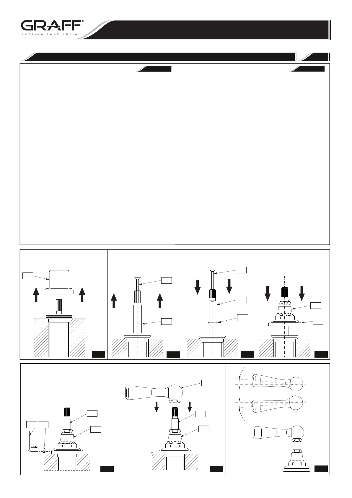
5. Repeat these steps for the second lever.
5. Repita estos pasos para la segunda palanca.
2
LEVER INSTALLATION INSTALACIÓN DE LA PALANCA
3.1

R1
B
C
7
6
10
3
4
3
K1 11
7
3
7
2
DELTA
DELTA
•
~
ESPANOL
See fig. 3.1-3.11
1. Remove the protective cap (R1) of the collar (R2).
3.
4. Turn the valve spindle to the left as far as possible (to the left). If you
should find it difficult to turn the spindle using your fingers, put the
lever body (2) on the spindle and turn the body to the left as far as
possible and remove the lever body from the spindle.
5. Put the lever body (2) on the valve spindle extension (7)
Check if it is possible to obtain the lever position as shown
in the picture 3.7. If you cannot obtain satisfactory position of the
lever (2)
in relation required position is visible – as shown
in the fig. 3.7), take off the lever (2) from the valve spindle extension
(7) - fig. 3.8. Unscrew the bolt (6) and switch the valve spindle
extension (7) by one tooth on the splines of the valve head and
screw in the bolt back (6)
.
lever (5) back on the valve spindle extension (7) and check if
the lever is set correctly - fig. 3.10.
– If the lever (5) position is
(12)
hex key (K2) as shown in fig. 3.11
– If the lever (5) position is still incorrect – move the valve spindle
extension (7) by one more tooth on the splines of the valve head
and check again if the lever (5) position is correct.
Ver las figs. 3.1-3.11
1. Retire la tapa protectora (R1) de la brida (R2).
3.
4. Gire el fuso de la válvula a la izquierda, alcanzando su máximo (en el
sentido antihorario). Si es difícil girar el fuso con los dedos, meta el
fuso en el cuerpo de la manilla (2) y gire el cuerpo a la izquierda y quite
del fuso el cuerpo de la manilla.
5. En la extensión del fuso de la válvula (7) meta el cuerpo de la manilla
(2) - fig. 3.6.
Compruebe si es capaz de posicionar la manilla según la fig. 3.7. Si no
es capaz de obtener la posición adecuada de la manilla (2) en relación
al borde de la superficie de montaje (perciirá un desplazamiento
significativo en el ángulo Δen relación a la posición requerida – como
en la fig. 3.7), quite la manilla (2) de la extensión del fuso de la válvula
(7) - fig. 3.8. Desenrosque el tornillo (6) y desplace la extensión
del fuso de la válvula (7) por un diente en la multichaveta del cabezal
de la válvula y vuelva a enroscar el tornillo (6)
Vuelva a meter la manilla (5) en la extensión del fuso de la válvula
(7) y compruebe la posición de la manilla - fig. 3.10.
– Si la posición de la manilla (5) es correcta,
apriete el tornillo (12)
con la llave allén (K2), según las figs. 3.11
– Si la posición de la manilla (5) sigue siendo incorrecta - desplace la
extensión del fuso de la válvula (7) por el diente siguiente en la
multichaveta del cabezal de la válvula y vuelva a comprobar la
posición de la manilla (5).
ENGLISH
shift by the angle Δ from the
to the edge of the installation surface (a clear
Put the
correct,tighten the screw with the
2.
(7)
Change a standard valve spindle to the valve spindle
(fig. 3.1). (7)
2. Reemplazar una extensión estandar para la valvula de extensión
(fig. 3.2-3.3).
- fig. 3.6.
(fig. 3.2-
3.3).
(fig. 3.1).
- fig. 3.9.
-fig.3.9.
Set the handle base and body (3,4) on the installation surface. Place
the base in the correct position in relation to the collar (R2) and
secure with a setting screw (11) using the provided hex key (K1) -
figs. 3.4-3.5.
En la superficie de montaje coloque la zócalo de la palanca y cuerpo
de la palanca (3,4). Posicione la base en relación a la brida (R2) y
asegúrela con el tornillo de fijación (11) usando la llave allén adjunta
(K1) - figs.3.4-3.5.
Rev.1 May 2017
2881.10GOI
4
ú
ESPANOL
The levers (items 2, fig. 1) are designed for full control of the water
stream. Full opening is achieved by opening the lever through 90°:
– clockwise – cold water lever located on the right,
– counterclockwise – hot water lever located on the left).
Water flow adjustment is made over the range 0° - 90°.
Las palancas (puntos 2, fig. 1) están diseñadas para el control completo
del flujo de agua. La abertura completa se logra al abrir la palanca
hasta los 90°:
– en el sentido de las agujas del reloj: palanca de agua fría ubicada a
la derecha,
– en sentido contrario a las agujas del reloj: palanca de agua caliente
ubicada a la izquierda.
El ajuste del flujo de agua se realiza sobre el intervalo de 0° a 90°.
ENGLISH
3
METHOD OF OPERATION •MÉTODO DE OPERACIÓN
ENGLISH
ú
ESPANOL
4
CARE AND MAINTENANCE •CUIDADO Y MANTENIMIENTO
ENGLISH
ú
ESPANOL
WARRANTY •GARANTÍA
Your product is designed and engineered in accordance with the
highest quality and performance standards. Be sure not to damage the
finish during installation. Care should be given to the cleaning of this
product. Although its finish is extremely durable, it can be damaged by
harsh abrasives or polish. Never use abrasive cleaners, acids,
solvents, etc. to clean any Graff product. To clean, simply wipe
gently with a damp cloth and blot dry with a soft towel.
Warranty conditions and warranty registration card are outlined on a
separate sheet.
Su producto de la Graff esta diseńado y dirigido acuerdo=con los estándares
de funcionamiento y calidad más altos. Este=seguro no dańar las
terminaciones del grifo durante la instalación. Cuide el producto
manteniendolo siempre limpio. Aunque su acabado es extremadamente
durable, puede ser dańado por los abrasivos o pulientes ásperos. Nunca
utilice limpiadores abrasivos, ácidos, solventes, el etc. para limpiar
cualquier producto de la Graff. Para limpiar, simplemente use un
pańo húmedo y seque con una toalla suave.
Las condiciones de la garantía y la tarjeta del registro de la garantía se
encuentran en una pagina separada.
All dimensions and drawings are for reference only. For details, please refer to actual products.
Todas las dimensiones y dibujos sirven únicamente de referencia. Para consultar detalles, ver los productos.
This faucet complies with NSF61/9, ASME/ANSI A112.18.1
and CSA B 125 Standards.
Este grifo se encuentra conforme con losestandares de NSF61/9,
de ASME/ANSI A112.18.1 y de CSA B 125. Installation Instructions Instrucciones de Instalación
BATH FAUCET, 3-hole type
GRIFO PARA BAÑO, diseño de 3 agujeros
3.9 3.10
3.11
3.8
2
7
6
7
2
7
K2 17
16
Graff
Rev.1 May 2017
2881.10GOI

This manual suits for next models

2

Other Graff Plumbing Product manuals

Graff IMMERSION 2150250 Operator's manual

Graff

Graff IMMERSION 2150250 Operator's manual

Graff BALI 2145000 Operator's manual

Graff

Graff BALI 2145000 Operator's manual

Graff G-6461-LM44 User manual

Graff

Graff G-6461-LM44 User manual

Graff E-8527 Operator's manual

Graff

Graff E-8527 Operator's manual

Graff SADE Operator's manual

Graff

Graff SADE Operator's manual

Graff 7090 User manual

Graff

Graff 7090 User manual

Graff C14B-WS Series User manual

Graff

Graff C14B-WS Series User manual

Graff UNI-BOX E-18000 Operator's manual

Graff

Graff UNI-BOX E-18000 Operator's manual

Graff PERFEQUE 5230 User manual

Graff

Graff PERFEQUE 5230 User manual

Graff CAMDEN 5149700 Operator's manual

Graff

Graff CAMDEN 5149700 Operator's manual

Graff INCANTO 5313000 Operator's manual

Graff

Graff INCANTO 5313000 Operator's manual

Graff PHASE G-6650-LM45B-T Series User manual

Graff

Graff PHASE G-6650-LM45B-T Series User manual

Graff G-8006 User manual

Graff

Graff G-8006 User manual

Graff TERRA G-6710-LM62B User manual

Graff

Graff TERRA G-6710-LM62B User manual

Graff INCANTO G-11255-LM55B T Series User manual

Graff

Graff INCANTO G-11255-LM55B T Series User manual

Graff PHASE G-6610-LM45B User manual

Graff

Graff PHASE G-6610-LM45B User manual

Graff AMETIS G-6440-LM43-T User manual

Graff

Graff AMETIS G-6440-LM43-T User manual

Graff VINTAGE Operator's manual

Graff

Graff VINTAGE Operator's manual

Graff G-4881-LM52 User manual

Graff

Graff G-4881-LM52 User manual

Graff b-collection 5127510 Operator's manual

Graff

Graff b-collection 5127510 Operator's manual

Graff ATLANTIS 1100-C2 User manual

Graff

Graff ATLANTIS 1100-C2 User manual

Graff 1130-LM2 T Series User manual

Graff

Graff 1130-LM2 T Series User manual

Graff CANTERBURY 2386000 Operator's manual

Graff

Graff CANTERBURY 2386000 Operator's manual

Graff 5306300 Operator's manual

Graff

Graff 5306300 Operator's manual

Popular Plumbing Product manuals by other brands

Sterling Plumbing Shower Receptor and Wall Surround 72110100 Specification sheet

Sterling Plumbing

Sterling Plumbing Shower Receptor and Wall Surround 72110100 Specification sheet

Ca'Bano 28001D installation guide

Ca'Bano

Ca'Bano 28001D installation guide

PEERLESS P299232 manual

PEERLESS

PEERLESS P299232 manual

Hans Grohe ShowerArc 26396001 Installation instructions / warranty

Hans Grohe

Hans Grohe ShowerArc 26396001 Installation instructions / warranty

Moen 3887 Series Specifications

Moen

Moen 3887 Series Specifications

ShowHouse Show House TS4712 Series Specification sheet

ShowHouse

ShowHouse Show House TS4712 Series Specification sheet

Kohler K-8207 installation guide

Kohler

Kohler K-8207 installation guide

Gessi QUADRO manual

Gessi

Gessi QUADRO manual

Blue Wave SA1320 owner's manual

Blue Wave

Blue Wave SA1320 owner's manual

Ponsi Rubinetterie Toscane Minimini Series Instructions for installation

Ponsi Rubinetterie Toscane

Ponsi Rubinetterie Toscane Minimini Series Instructions for installation

Grohe Tectron 37 324 installation instructions

Grohe

Grohe Tectron 37 324 installation instructions

Hans Grohe Starck X 10071001 Specification sheet

Hans Grohe

Hans Grohe Starck X 10071001 Specification sheet

Dynamic DYN-6220-01 instruction manual

Dynamic

Dynamic DYN-6220-01 instruction manual

Haws 8330 Installation, operation & maintenance instructions

Haws

Haws 8330 Installation, operation & maintenance instructions

Franke FFPD100 SERIES installation guide

Franke

Franke FFPD100 SERIES installation guide

Tylo Combi 7 quick start guide

Tylo

Tylo Combi 7 quick start guide

Casa Lusso eden installation instructions

Casa Lusso

Casa Lusso eden installation instructions

Brizo ATAVIS 88742 quick start guide

Brizo

Brizo ATAVIS 88742 quick start guide

manuals.online logo
manuals.online logoBrands
  • About & Mission
  • Contact us
  • Privacy Policy
  • Terms and Conditions

Copyright 2025 Manuals.Online. All Rights Reserved.