Graham Field LUMEX FR566GH Manual instruction

FR566GH-INS-LAB-RevA10
1
FR566GH / FR566DGH Specialty HealtHcaRe SeatinG Heat
anD MaSSaGe Unit: SetUp anD OpeRatiOn inStRUctiOnS
pleaSe SaVe tHeSe inStRUctiOnS FOR FUtURe USe
Note: The most current version of these instructions can be found online at www.grahamfield.com
Tools required: 1/4" hex wrench, 3/8" hex wrench, Phillips screwdriver, masking or packaging tape
WARNING: Important! Read and understand these instructions before assembling or us-
ing the Specialty Healthcare Seating Heat and Massage Unit. If you do not understand
any part of these warnings, cautions or instructions, contact a healthcare professional
for direction in the use of this product. If the Heat and Massage Unit is not properly as-
sembled, personal injury and damage to the Heat and Massage Unit could result.
WARNING: The recliner seat and back heating elements are wired to operate in series
only. Do not change the system wiring in any way.
WARNING:
If components are damaged or missing, contact your dealer immediately. DO
NOT use substitute parts. Use only Lumex replacement parts. The use of non-Lumex re-
placement parts could cause personal injury, property damage, and void the warranty.
WARNING: GF Health Products, Inc. assumes no responsibility for any damage or injury
caused by improper assembly or use of this product.
CAUTION: If the FR566DGH arm with the Switch Box is removed for service or replacement,
ensure that before removal, to prevent damage, 1) the Selector Switch cable is disconnected
from the Control Module, and 2) the cushioned clamp that secures the Selector Switch cable
to the recliner's rear frame crossbar is removed from the cable.
Note: Products Affected: FR566GH and FR566DGH. These instructions are for Heat and Mas-
sage Unit setup and operation only; please see the Operating Instructions that came with
your recliner for recliner assembly and operation instructions.
Description
The Lumex Specialty Healthcare Seating Heat and Massage
Unit is a low-voltage (12V) Heat and Massage Unit, control-
lable by the user and / or caregiver, designed to enhance the
comfort of the patient / resident during the use of Lumex Clini-
cal Care Recliners. The Heat and Massage Unit offers three lev-
els of seat and back heat, as well as a gentle or rm massage
function for just lower back or both lower and upper back.
Connection
The Heat and Massage Unit comes pre-installed in Lumex
Clinical Care Recliners with the Heat and Massage Option
(FR566GH and FR566DGH). During recliner shipment, the
Heat and Selector Switch connections are disconnected;
several easy connections are all that is required to make
the unit functional.
Main Components
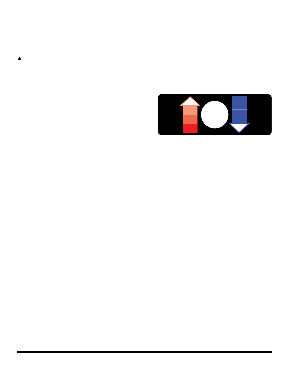
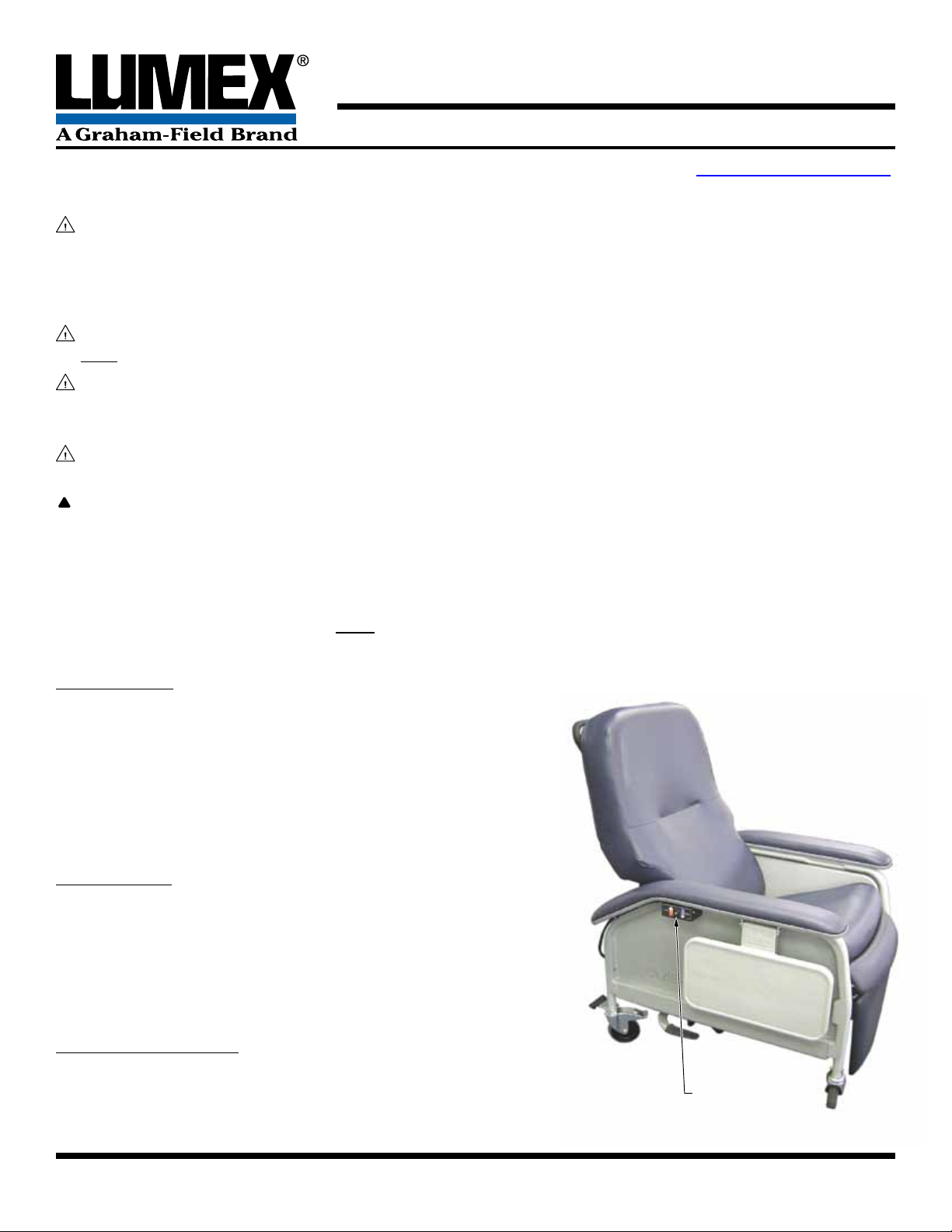
1. The Selector Switch (shown at right), in the Switch Box
mounted on the right side of the recliner underneath
the armrest, is a single multi-position switch that acti-
vates both the Heat and Massage functions. Selector Switch (mounted
underneath right armrest)
Selector Switch

FR566GH-INS-LAB-RevA10
2
2. The Control Module, the brains
of the system, is inside the
Junction Box. Both are shown
at right.
3. The Power Supply, which has
an 8-foot power cord that plugs
into the wall power outlet, is
shown at right.
Heat and Massage Unit Setup Instructions
1. Place the back cushion over the vertical blades of the
recliner mechanism. Secure it on each side with the
threaded screw knobs enclosed with the Recliner Oper-
ating Instructions, as shown at right.
2. Raise the ap in the lower rear of the back cushion and
use masking or packaging tape to temporarily secure it.
This will permit uninterrupted access to the back com-
partment while making the nal cable connections.
3. Use a 1/4" hex wrench to remove the two hex head
screws that secure the Junction Box cover (see picture
of Junction Box at top of page). Remove the Junction
Box cover to expose the Control Module.
4. Insert the switch box cable connector (labeled
SWITCH) and the two connectors (labeled HEAT and
HEAT A) and cable leading from the rear of the seat
cushion into the plastic bushing in the bottom of the
back cushion and pull them through into the back com-
partment, as shown at right.
5. Insert the seat cushion cable connector (labeled
HEAT A) into the connector labeled HEAT A already in
the back compartment until its locking tabs snap into place.
6. Insert the connector labeled HEAT into the connector also labeled HEAT in the left side of the
Control Module (see picture of Control Module at top of page) until its locking tab snaps into
place.
7. Insert the connector labeled SWITCH into the connector also labeled SWITCH in the right side
of the Control Module (see picture of Control Module at top of page) until its locking tab snaps
into place.
8. See picture at right. Remove the lock nut from the
screw that secures the cushioned cable clamp. Remove
the clamp and place it around the switch box cable.
Slide the clamp over the cable until the holes in the
clamp tabs are in line with the screw, then pinch them
closed. Install the clamp tabs on the screw, then rein-
stall the lock nut on the screw. Hold the lock nut with
a 3/8" hex wrench and tighten the screw with a Phillips
screwdriver.
Control Module (Junction
Box cover removed)
Junction Box Power Supply
Secure Back Cushion to
Recliner Mechanism
Knob
recliner
mechanism
knob
Insert cables through
back cushion bushing
backcushion
bushing
cables
Secure Switch Box
cable clamp
switchboxcable clamp
screw
locknut
clamptabs

FR566GH-INS-LAB-RevA10
3
9. Place the cable labeled HEAT A inside the Junction Box. Replace the Junction Box cover; re-
place the two hex head screws that secure the Junction Box cover. Use a 1/4" hex wrench to
secure the screws.
10. Remove the tape holding the back ap. Lower the ap and seal the compartment.
11. The Heat and Massage Unit is now ready for operation; instructions for use follow.
CAUTION: Before rolling the recliner, ensure the power cord is unplugged from the AC
outlet.
Heat and Massage Unit Operation Instructions
1. Plug the Power Supply Cord into any grounded
outlet.
2. The Heat and Massage Unit is operated using
the Single Multi-Position Selector Switch located
on the Right Side of the Recliner underneath the
Armrest. The Heat and Massage Functions can
be operated independently. The Selector Switch
faceplate is shown at right.
3. Press the Selector Switch UP to activate the
HEAT FUNCTION.
4. Press the Selector Switch DOWN to activate the
MASSAGE FUNCTION.
5. The Selector Switch has THREE HEAT SETTINGS and FOUR MASSAGE SETTINGS as follows:
6. HEAT FUNCTIONS:
a. Press Selector Switch UP for Setting 1: High Heat, 106°F (41°C), brightest LED
b. Press Selector Switch UP AGAIN for Setting 2: Medium Heat, 104°F (40°C), bright LED
c. Press Selector Switch UP AGAIN for Setting 3: Low Heat, 100°F (37°C), dim LED
d. Press Selector Switch UP AGAIN: Heat Function shuts off.
e. There is a small Red Indicator Light, which illuminates only during the Heat Function, in the
Selector Switch. The light's brightness is determined by the Heat Level being used:
Brightest = High Heat; Dimmest = Low Heat.
7. MASSAGE FUNCTIONS:
a. Press Selector Switch DOWN for Setting 1: Gentle Lower Back Massage
b. Press Selector Switch DOWN AGAIN for Setting 2: Firm Lower Back Massage
c. Press Selector Switch DOWN AGAIN for Setting 3: Gentle Upper and Lower Back Massage
d. Press Selector Switch DOWN AGAIN for Setting 4: Firm Upper and Lower Back Massage
e. Press Selector Switch DOWN AGAIN: Massage Function Shuts Off.
8. The Heat and Massage Unit automatically shuts off at the following times:
a. HEAT FUNCTION: After One Hour of Continuous Use at the Same Level
b. MASSAGE FUNCTION: After Fifteen Minutes of Continuous Use at the Same Level
c. To restart the Heat and Massage Unit, follow the instructions above.
If you have any questions about the setup and/or operation of the Heat and Massage Unit, please
call the Graham-Field Technical Support Group at 800-347-5678.
Press Up
For Heat
Press Down
For Massage
OFF
1 GENTLE
LOWER BACK
2 FIRM
LOWER BACK
3 GENTLE
UPPER & LOWER
BACK
4 FIRM
UPPER & LOWER
BACK
OFF
3
LOW
2
MEDIUM
1
HIGH

FR566GH-INS-LAB-RevA10
4
© 2010 GF Health Products, Inc. • 2935 Northeast Parkway • Atlanta, GA 30360 • tel 800-347-5678 • fax 800-721-0601 • www.grahameld.com
GF Health Products, Inc. is not responsible for typographical errors.
Packaging, warranties, products and specications are subject to change without notice.
Graham-Field and Lumex are registered trademarks of GF Health Products, Inc.
Technical Specications
For complete technical specications, please call the Graham-Field Technical Support Group at
800-347-5678.
Limited Two-Year Warranty
GF Health Products, Inc. warrants the Lumex®Specialty Healthcare Seating Heat and Massage Unit
for two years against manufacturer's defects. If a product is deemed to be under warranty, GF
Health Products, Inc. shall provide, at its option, (1) replacement of any defective part or product
or (2) a credit of the original selling price made to GF Health Products, Inc.'s initial customer. The
warranty does not include any labor charges incurred in replacement part(s) installation or any
associated freight or shipping charges to GF Health Products, Inc.
This manual suits for next models
1
Table of contents
Other Graham Field Massager manuals