7
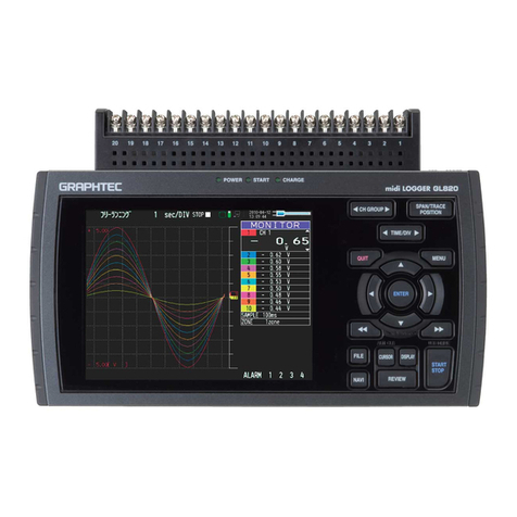
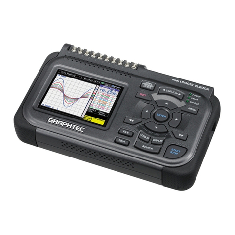
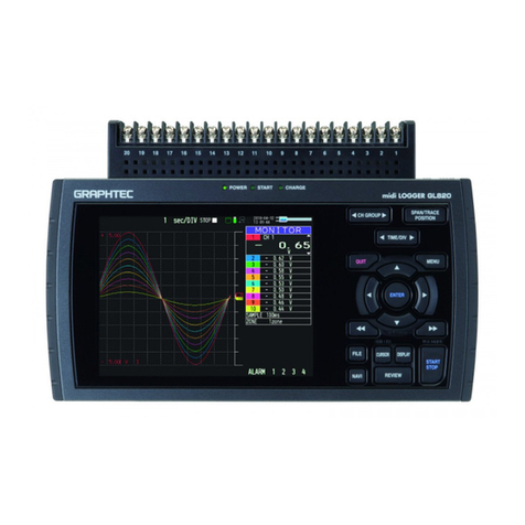
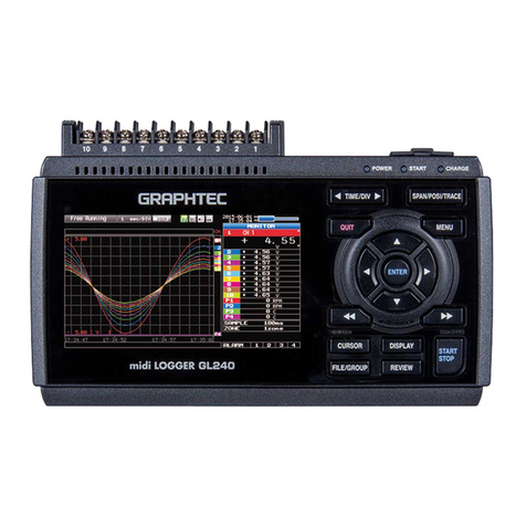
Press the [MENU] key to open a setup menu. Each time this key is pressed, the
setup screen tabs change in the sequence shown below.
3.MENU
Press the [QUIT] key to cancel the settings and return them to their default status.
If the device is in the Remote (Key Lock) status that the device is operated by the
computer via the interface, press this key to return the device to the normal
operating status (Local).
4.QUIT (LOCAL)
These keys are used to select menu setup items, to make span settings in the digital
display area, to move the cursors during a data replay operation, and so forth.
5.Keys (DIRECTION KEYS)
Press the [ENTER] key to enter the settings made in the setup menus, and to
confirm your settings.
6.ENTER
Used to move the cursor at high speed during replaying or change the operation
mode in the file box. Hold down both keys simultaneously for at least two seconds
to enable key lock status.
To cancel key lock status, press them again for at least two seconds.
The key lock status can be confirmed in whether or not the key lock lamp on the
monitor is lit in yellow.
* Pressing these keys simultaneously with the key + ENTER + key enables password protection
for the key lock operation.
7.Keys (KEY LOCK)
Points to Remember
•AMP Settings
Used to set the input, range, filter and other settings.
•Data Capture Settings
Used to set settings such as the sampling interval, data capture
destination, and calculations during data capture.
•Trigger Settings
Used to specify data capture start and stop conditions, and alarm
conditions.
•Interface Settings
Used to set the USB ID.
•Wireless LAN setting
(displayed when the option is installed)
Used to set the connection to the wireless LAN after the wireless
unit is installed.
•Other Settings
Used to set the screen brightness, background color, and language,
etc.
AMP
DAT (DATA)
TRG (TRIG)
I/F
LAN
OTH (OTHR)
