Gravely 891006 User manual

Owner/Operator & Parts Manual
Model
891006
04597200A 2/13
Printed in USA
Grass Collection System

2
Safety . . . . . . . . . . . . . . . . . . . . . . . . . . . . . . . . . . . . . . 3
Assembly . . . . . . . . . . . . . . . . . . . . . . . . . . . . . . . . . . . 6
Removal . . . . . . . . . . . . . . . . . . . . . . . . . . . . . . . . . . . 12
Operation . . . . . . . . . . . . . . . . . . . . . . . . . . . . . . . . . . 12
Maintenance. . . . . . . . . . . . . . . . . . . . . . . . . . . . . . . . 14
Storage . . . . . . . . . . . . . . . . . . . . . . . . . . . . . . . . . . . . 15
Troubleshooting. . . . . . . . . . . . . . . . . . . . . . . . . . . . . 15
Specifications. . . . . . . . . . . . . . . . . . . . . . . . . . . . . . . 15
Parts List. . . . . . . . . . . . . . . . . . . . . . . . . . . . . . . . . . . 16
Warranty . . . . . . . . . . . . . . . . . . . . . . . . . . . . . . . . . . . 22
THE MANUAL
Before operation of unit, carefully and completely read
this Manual and the unit’s Owner/Operator Manual. The
contents will provide you with an understanding of safety
instructions and controls during normal operation and
maintenance.
All reference to left, right, front, or rear are given from
operator sitting in operation position and facing the
direction of forward travel.
MODEL AND SERIAL NUMBERS
When ordering replacement parts or making service
inquiries, know the Model and Serial numbers of your
unit.
Numbers are located on the product registration form in
the unit literature package. They are printed on a serial
number label, located on the frame of your unit.
• Record Unit Model and Serial numbers here.
PRODUCT REGISTRATION
The Gravely dealer must register the product at the time
of purchase. Registering the product will help the
company process warranty claims or contact you with the
latest service information. All claims meeting
requirements during the limited warranty period will be
honored, whether or not the product registration card is
returned. Keep a proof of purchase if you do not register
your unit.
Customer Note: If the dealer does not register your
product, please fill out, sign, and return the product
registration card to Gravely.
UNAUTHORIZED REPLACEMENT PARTS
Use only Gravely replacement parts. The replacement of
any part on this unit with anything other than a Gravely
authorized replacement part may adversely affect the
performance, durability, and safety of this unit and may
void the warranty. Gravely disclaims liability for any
claims or damages, whether warranty, property damage,
personal injury or death arising out of the use of
unauthorized replacement parts.
DELIVERY
Customer Note: If you have purchased this product
without complete assembly and instruction by your
retailer, it is your responsibility to:
• Read and understand all assembly instructions in
this manual. If you do not understand or have
difficulty following the instructions, contact your
nearest Gravely Dealer for assistance.
NOTE: To locate your nearest Gravely Dealer, go to
www.gravely.com on the Internet.
Before attempting to operate your unit:
1. Make sure all assembly has been properly
completed.
2. Understand all Safety Precautions provided in the
manuals.
TABLE OF CONTENTS
INTRODUCTION
Serial
Number
Label
Figure 1
WARNING: Improper assembly or adjustments
can cause serious injury.

3
3. Review control functions and operation of the unit.
Do not operate the unit unless all controls function
as described in this manual.
4. Review recommended lubrication, maintenance
and adjustments.
5. Review Limited Warranty Policy.
6. Fill out a product registration card and return the
card to the Ariens Company or go to
www.gravely.com.
DISCLAIMER
Gravely reserves the right to discontinue, change, and
improve its products at any time without notice or
obligation to the purchaser.
The descriptions and specifications contained in this
manual were in effect at printing. Equipment described
within this manual may be optional. Some illustrations
may not be applicable to your unit
SAFETY ALERTS
Look for these symbols to point out
important safety precautions. They mean:
Attention!
Personal Safety Is Involved!
Become Alert!
Obey The Message!
The safety alert symbols above and signal
words below are used on decals and in this manual.
Read and understand all safety messages.
NOTATIONS
NOTE: General reference information for proper
operation and maintenance practices.
IMPORTANT: Specific procedures or information
required to prevent damage to unit or attachment.
PRACTICES AND LAWS
Practice usual and customary safe working precautions,
for the benefit of yourself and others. Understand and
follow all safety messages. Be alert to unsafe conditions
and the possibility of minor, moderate, or serious injury or
death. Learn applicable rules and laws in your area.
Always follow the practices set forth in this manual.
REQUIRED OPERATOR TRAINING
Original purchaser of this unit was instructed by the seller
on safe and proper operation. If unit is to be used by
someone other than original purchaser; loaned, rented or
sold, ALWAYS provide this manual and any needed
safety training before operation.
SAFETY DECALS AND LOCATIONS
ALWAYS replace missing or damaged Safety Decals.
Refer to Figure 2 below for Safety Decal locations.
SAFETY
DANGER: IMMINENTLY HAZARDOUS
SITUATION! If not avoided, WILL RESULT in
death or serious injury.
WARNING: POTENTIALLY HAZARDOUS
SITUATION! If not avoided, COULD RESULT in
death or serious injury.
CAUTION: POTENTIALLY HAZARDOUS
SITUATION! If not avoided, MAY RESULT in
minor or moderate injury. It may also be used to
alert against unsafe practices.
077541
• Stop engine and wait for al l
moving par ts to stop bef ore
opening cover.
•Avoid tip over and loss of
control:
DO NOToverload bagger.
Use extreme caution on
slopes.
DO NOT make abrupt
turns or speed changes.
•Weight kit isrequired when
specied.
• Be aware of new turning
radius.
•Arrêterlemoteur et attendrel’arrêt
complet de toutes les pièces en
mouvementavant d’ouvrir le
couvercle.
•Éviter lebasculement et la per tede
contrôle de la machine:
NE PAS surcharger l’ensacheuse.
Faire preuve d’extrême prudence
sur les pentes.
NE PAS e ectuer desvirages serrés
et des changements de vitesses
soudains.
• Le ki t d e masses est requ is lor squ e
cela est spécié.
•Fa ire attention au nouveau ra yon
de braquage.
• Apagar el motor y esperar a que
todas las piezas móviles se
detengan ant esde abr ir lacubierta.
• Evitar el vuelco y la pérdida de
control:
NO sobrecargar la embolsadora.
Tener cuidado en las pendientes.
NO realizar giros o cambios de
velocidad bruscos.
• El juego de contrapesos es
necesario cuando se especique .
•Tener cuidado con el nuevo radio
de giro.
05359700
BAG IS SUBJECT TO WEAR AND
DETERIORATION.
CHECK BAG FEQUENT LY, REPLACE WHEN
NECESSARY.
USE ORIGINAL BAG TO COMPLY WITH SAFETY
SPECIFICATIONS.
LE SAC EST SOUMIS À L’ USURE ET A LÀ
DÉTÉRIORATION.
VÉRIFIER LE SAC FRÉQUEMMENT. LE
REMPLACER AU BESOIN.
UTILISER UN BAC D’ORIGINE CONFORME
AUX NORME DE SECURITE.
LA BOLSA ESTA SUJETA A DESGASTEY
DETERIORO.
REVISAR LA BOLSA FREQUENT AMENTE,
Y REEPLAZARLA SI ES NECESARIO.
USAR BOLSAS ORIGINAL PARA CUMPLIR CON
LAS ESPECIFICACIONES DE SEGURIDAD.
ATTENTION
PRECAUCION
CAUTION
•
•
•
•
•
•
•
•
•
07742300B
WARNING / AVERTISSEMENT / ADVERTENCIA
1
2
3
4
5
6
Figure 2
© Copyright 2013 Ariens Company

4
1. WARNING!
Stop engine and wait for all moving parts to
stop before opening cover.
Avoid tip over and loss of control:
DO NOT overload bagger.
Use extreme caution on slopes.
DO NOT make abrupt turns or speed changes.
Weight kit is required when using bagger.
Be aware of new turning radius.
2. DANGER!
To Avoid Serious Injury
DO NOT operate mower unless guards
are in place or grass pump and entire
bagger are attached.
ALWAYS wear adequate hearing protection.
ROTATING FAN! Stop engine and remove
key before clearing.
Wait for all moving parts to stop.
Keep children and others away from unit
while operating.
3. DANGER ROTATING PARTS
Always keep feet and hands away from
rotating parts.
Never direct discharge towards persons or
property that may be injured or damaged by
thrown objects.
Keep people away from unit while operating.
Shut off engine, remove key, read manual
before you adjust or repair unit.
NO STEP! Always keep feet away from
rotating parts.
4. CAUTION
• Bag is subject to wear and deterioration.
• Check bag frequently, replace when necessary.
• Use original bag to comply with safety
specifications.
5. KEEP GUARDS IN PLACE
Do not operate mower unless guards are in
operating position or bagger is attached.
6. DANGER! HOT SURFACES
DO NOT TOUCH parts which are hot from
operation. Always allow parts to cool.
SAFETY RULES
Read, understand, and follow all safety practices in this
Manual, Owner/Operator Manual, and Engine Manual
before beginning assembly. Failure to follow instructions
could result in personal injury and/or damage to unit.
ALWAYS remove key and wire from spark plugs on unit
before assembly. Unintentional engine start up can cause
death or serious injury.
Sharp edges can cut. Movement of parts can cut off
fingers or a hand. Wrap blade(s), wear sturdy gloves and
use extreme caution when working near blades.
Installing the blower assembly on your mower requires
the removal of the discharge chute deflector and belt
guard. Retain discharge chute, hinge pin, belt guard and
belt guard hardware in a safe location and reinstall
whenever operating unit without the blower assembly.
DO NOT operate mower unless guards are in place or
blower assembly and entire bagger are attached.
Always install counterweights on front axle before
operating unit with bagger attached. Always remove
counterweights from front axle when bagger is removed
from the unit.
Complete a walk around inspection of unit and work area
to understand:
• Work area • Your unit • All safety decals
ALWAYS check overhead and side clearances carefully
before operation. ALWAYS be aware of traffic when
operating along streets or curbs.
Keep children and people away. Keep children out of
work area and under watchful care of a responsible adult.
NEVER allow children to operate or play on or near unit.
Be alert and shut off unit if children enter area.
OTt2080
OL4840
OL4690
OL0900
OL4140
OL3030
OL0910
OL4140
OL4010
OL4420
OL4430
OL3320
OT1281

5
Keep area of operation clear of all toys, pets, and debris.
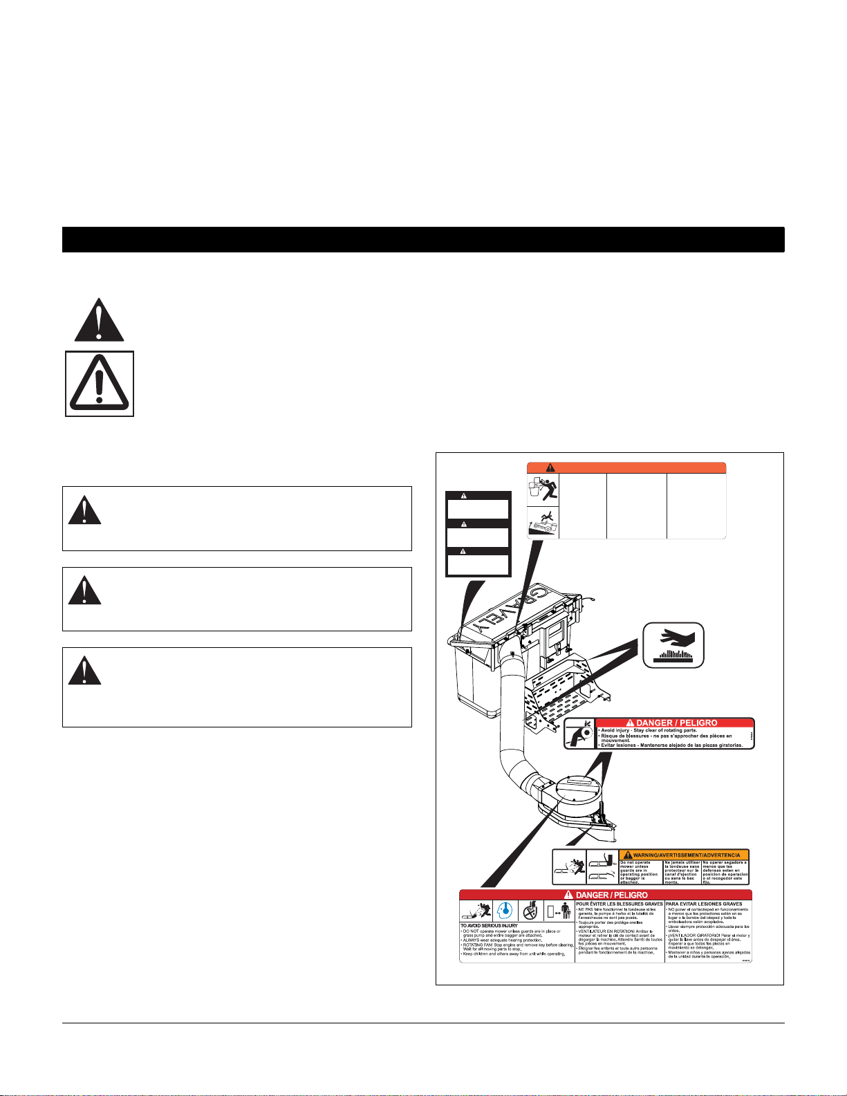
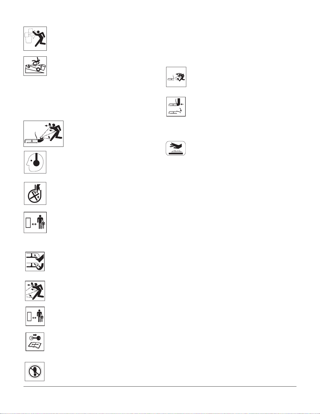
Thrown objects can cause injury.
Check for weak spots on docks, ramps or floors. Stay
alert for hidden hazards.
Avoid uneven and rough terrain. DO NOT operate near
drop-offs, ditches, or embankments. Unit can suddenly
turn over if a wheel is over the edge of a cliff or ditch, or if
an edge caves in.
Dust, fog, etc. can reduce vision and cause an accident.
Operate unit only when there is good visibility and light.
Only trained adults may operate unit.
Training includes actual operation.
NEVER operate unit after or during the use of
medication, drugs or alcohol. Safe operation requires
your complete and unimpaired attention at all times.
NEVER allow anyone to operate this unit when their
alertness or coordination is impaired.
Wear adequate safety gear and protective gloves. Wear
proper footwear to improve footing on slippery surfaces.
DO NOT wear loose clothing or jewelry and tie back hair
that may get caught in rotating parts.
Protect eyes, face and head from objects that may be
thrown from unit. Wear appropriate hearing protection.
Avoid sharp edges. Sharp edges can cut. Moving parts
can cut off fingers or a hand.
ALWAYS keep hands and feet away from all rotating
parts during operation. Rotating parts can cut off body
parts.
NEVER place your hands or any part of your body or
clothing inside or near any moving part while unit is
running.
ALWAYS disengage attachment, stop unit and engine,
remove key and allow moving parts to stop before
leaving operator’s position.
Understand:
• How to operate all controls
• The functions of all controls
• How to STOP in an Emergency
• Braking and steering characteristics
• Turning radius and clearances
DO NOT operate unit with bagger unless front weight is
installed.
NEVER operate bagger if the unit’s safety interlock
system is not working properly.
Always be aware of maximum sweep of bagger when
turning. Always allow adequate clearance between
bagger, personnel and other objects when turning.
As grass catcher fills, be alert to changing unit stability
and control.
Disengage PTO when attachment is not in use.
ALWAYS disengage PTO, stop unit and engine, remove
key, engage parking brake and allow moving parts to stop
before leaving operator’s position.
DO NOT operate at too fast a rate. DO NOT change
engine governor settings or over-speed engine. Slow
down before turning.
DO NOT mow near dropoffs, ditches or embankments.
The mower could suddenly turn over if a wheel is over
the edge of a cliff or ditch, or if an edge caves in.
DO NOT mow on wet grass. Reduced traction could
cause sliding.
DO NOT try to stabilize the machine by putting your foot
on the ground.
Know the weight of loads. Limit loads to those you can
safely control and the unit can safely handle.
ALWAYS keep protective structures, guards and panels
in good repair, in place and securely fastened.
DO NOT operate in reverse unless absolutely necessary.
ALWAYS look down and behind before and while
backing.
Watch for holes, ruts, or bumps. Uneven terrain could
overturn the machine.
ALWAYS allow adequate clearance for unit, attachments,
operator and objects in work area when turning. Slow
down before turning.
NEVER carry passengers.
If you cannot back up a slope or you feel uneasy on it, do
not mow it.
Mow up and down slopes, not across them.
Keep all movements on the slope slow and gradual. DO
NOT make sudden changes in speed or direction.
Avoid starting or stopping on a slope. If tires lose traction,
disengage the blades and proceed slowly straight down
the slope.
DO NOT operate on slopes over 10°.
DO NOT park on slopes unless absolutely necessary. If
you must park on a slope, always chock or block wheels.
Always set parking brake.
Use a slow speed. Avoid changing speeds on slopes.
Tires may lose traction on slopes even though the brakes
are functioning properly.
Use extra care when loading or unloading unit on trailer
or truck.
Disengage PTO, stop engine, remove key and wait for all
moving parts to stop before servicing, making repairs,
adjusting or when clearing debris.
ALWAYS block wheels. Know all jack stands are strong,
secure and will hold weight of unit during maintenance.
ALWAYS keep protective structures, guards, and panels
in good repair, in place and securely fastened. NEVER
modify or remove safety devices.
Keep unit free of grass, leaves, or other debris. Clean up
oil or fuel spills.

6
Check bags and bagger parts prior to each use for any
holes, abrasions, mildew, or structural damage. Replace
parts when necessary.
Keep all hardware properly tightened.
Maintain or replace safety and instruction labels, as
necessary.
Keep unit free of debris. Clean up oil or fuel spills.
DO NOT store bags with grass in them.
DO NOT use double blade kits while bagging.
For extended storage, clean unit thoroughly. See Engine
Manual for proper storage.
ALWAYS lower cutting mower deck when unit is parked
or stored.
Use only attachments or accessories designed for your
unit and properly installed.
Check attachment components frequently. If worn or
damaged, replace with manufacturer’s recommended
parts.
Grass catcher components are subject to wear, damage
and deterioration, which could expose moving parts or
allow objects to be thrown. Frequently check components
and replace with manufacturer’s recommended parts,
when necessary.
TOOLS REQUIRED
• Wrenches: 1/2", 9/16", 3/4"
•Drill
• 13/32" Drill Bit
• Utility Knife
UNPACKING UNIT
IMPORTANT: Remove contents from carton carefully.
Place cover assembly on a flat piece of cardboard to
avoid scratching it.
Package Contents:
Check the contents of your kit for the parts listed in
Figure 3:
ASSEMBLY
WARNING: AVOID INJURY. Read and
understand the entire Safety section before
proceeding.
Item Description Qty Part Number
1 Inlet Adapter 1 59102000
2 Two-Bag Receptacle 1 00458900
3 Upper Mount 1 01065451
4 Lower Mount 1 04570251
5 Counterweight Bracket 1 03859451
6 Counterweight 2 03859551
7 Grass Bag 2 59207600
8 Blower Assembly 1 59215900
9 Hose 1 04588400
10 5/16-18 x 3/4 Hex Bolt 4 05947000
11 5/16-18 x 2 1/4 Hex Bolt 6 05963700
12 3/8-16 x 3/4" Hex Bolt (60"
Mower Deck) 1 05959400
13 3/8-16 x 1 Hex Bolt 8 05948700
14 1/2-13 x 1 1/2 Round Head
Square Neck Bolt 2 06223100
15 1/2-13 x 1 1/4 Round Head
Square Neck Bolt 2 06224700
16 3/8-16 x 1 3/4 Round Head
Square Neck Bolt 2 06223800
17 1/2-13 Lock Top Flange Nut 4 06543600
18 5/16-18 Nyloc Flange Nut 10 06545400
19 3/8-16 Nyloc Flange Nut 10 06545500
20 3/8 Push Nut 2 07009900
21 3/8-16 Wing Nut 2 07500109
22 3/8 x .115 Heavy Locking
Washer 2 06306500
23 13/32 x 1-1/2 x 15/64 Flat
Steel Washer 2 06400006
24 11/32 x 11/16 x 1/16 Flat Steel
Washer 6 06437200
25 7/16 x 1 x 5/64 Flat Steel
Washer 8 06435900
26 V-Belt – 48" Mower Deck
V-Belt – 52" Mower Deck
V-Belt – 60" Mower Deck
1
1
1
07200634
07200635
07200636
27 48" Blower Baffle – Front 1 04590651
28 52" Blower Baffle – Front 1 04589951
29 60" Blower Baffle – Front 1 04589851
Item Description Qty Part Number

8
INSTALL COUNTERWEIGHTS (FIGURE 4)
1. Install the counterweight bracket (item 5) on the
frame using two 1/2-13 x 1 1/4 roundhead square
neck bolts (item 15) and two 1/2-13 nyloc flange
nuts (item 17). See Figure 4.
NOTE: User may need to remove (2) tapping screws and
Gravely backing plate.
2. Fasten the weight plates (item 6) to the
counterweight bracket (item 5) using two 1/2-13 x 1
1/2 round head square neck bolts (item 14) and two
1/2-13 nyloc flange nuts (item 17). See Figure 4.
NOTE: The weights will rest on the counterweight
bracket.
INSTALL BAGGER MOUNT (FIGURE 5 AND
FIGURE 6)
1. Raise the rear of the unit and support it securely on
jack stands.
2. Remove original rear bumper by removing four
tapping screws holding it to the frame as shown in
Figure 5.
3. Install the lower mount weldment (item 4) on the
main frame with six 11/32 x 11/16 x 1/16 flat
washers (item 24), six 5/16-18 x 2 1/4 hex bolts
(item 11) and six 5/16-18 nyloc flange nuts
(item 18). See Figure 6.
CAUTION: Always install counterweights on the
front axle before operating unit with bagger
attached. Always remove counterweights from
front axle when bagger is removed from the
unit.
Figure 4
14
5
15
15
17
17
17
6
CAUTION: Support rear bumper and bagger
mount when removing and installing
components.
CAUTION: ALWAYS block wheels and know all
jack stands are strong and secure and will hold
weight of unit during maintenance.
Figure 5
Remove these two
tapping screws.
18
4
11 24
Figure 6

9
ASSEMBLE CATCHER (FIGURE 7)
1. Attach inlet adapter (item 1) onto receptacle
assembly (item 2) with (4) 5/16-18 x 3/4 hex bolts
(item 10) and 5/16-18 nyloc nut (item 18).
2. Enlarge mounting holes in receptacle (item 2) to
13/32" diameter.
3. Attach receptacle assembly (item 2) onto upper
mount (item 3) with eight 3/8-16 x 1 hex bolts
(item 13), eight 7/16 x 1 x 5/64 flat steel washers
(item 25) and eight 3/8-16 nyloc nuts (item 19).
ATTACH CATCHER TO LOWER MOUNT
(FIGURE 8)
1. Secure 3/8-16 x 1 3/4 round head square neck bolts
(item 16) and 13/32 x 1 1/2 x 15/16 flat washers
(item 23) to upper mount (item 3) with 3/8 push nut
(item 20).
2. Slide catcher assembly into lower mount (item 4).
Rotate up and secure with 3/8-16 nyloc nut
(item 19) or 3/8" wing nut (item 21) and 3/8 x .115
locking washer (item 22).
NOTE: For ease of assembly, use latch attached to
upper mount (item 3) to temporarily hold the mount onto
lower mount (item 4) while securing mounting hardware.
3. Install grass bag (item 7) in cover assembly
(item 2).
Item Description Item Description
1 Inlet Adapter 13 3/8-16 x 1 Hex Bolts
2 Receptacle 18 5/16-16 Nyloc Nut
3 Upper Mount 19 3/8-16 Nyloc Nuts
10 5/16-18 x 3/4 Hex
Bolts 25 7/16 x 1 x 5/64 Flat
Washers
Figure 7
2
13
13
18
19
25
10
Mounting
Holes
Item Description Item Description
2 Receptacle 20 3/8 Push Nut
3 Upper Mount 21 3/8-16 Wing Nut
(Optional Tooless
Hardware)
4 Lower Mount 22 3/8 x .115 Heavy
Locking Washer
(Optional Tool-less
Hardware)
16 3/8-16 x 1 3/4
Round Head
Square Neck Bolt
23 13/32 x 1-1/2 x
15/64 Flat Steel
Washer
19 3/8-16NylocFlange
Nut Figure 8
3
4
2
23
19
21
20
16
22
Latch

10
INSTALL BLOWER ASSEMBLY (FIGURE 9)
Install Front Baffle to Blower Assembly
1. Choose the appropriate baffle and install to blower
assembly according to Figure 9.
NOTE: 60" Mower deck requires 3/8-16 x 3/4" hex bolt
(item 12).
INSTALL BLOWER ASSEMBLY (FIGURE 10)
1. Remove discharge chute.
2. Position blower assembly (item 8) at discharge
chute opening.
3. Install blower assembly (item 8) on mower deck.
Install pin thru bracket on mower deck.
INSTALL V-BELT ON BLOWER ASSEMBLY
(FIGURE 11 AND FIGURE 12)
There are three V-belts included in the bagger kit with a
part number on each V-belt:
• 48" mower deck V-belt (07200634)
• 52" mower deck V-belt (07200635)
• 60" mower deck V-belt (07200636)
NOTE: To increase belt tension add washers to the
compression spring. Decrease tension by removing
washers. Four washers for 48" and 52", two washers for
60" decks (figure 11).
CAUTION: Make sure blower assembly covers
the discharge chute opening so no debris can
escape.
Item Description
8 Blower Assembly
Figure 10
Mower Deck Baffle Measurements
48" 7-1/8"
52" 5-3/4"
60" 2-7/8"
Front Blower Baffle (item 27, 28 and 29)
Figure 9
12
Idler Disengage
Bend tab down
as needed to
obtain a snug fit
onto mower
deck assembly.
8
Pin
4 washers for 48 & 52" decks
2 washers for 60" decks
Figure 11

11
INSTALL V-BELT ON DOUBLE PULLEY
(FIGURE 12)
IMPORTANT: Ensure the flat side of V-belt contacts idler
pulley and the V-side of V-belt contacts drive pulley and
double pulley.
1. Remove the hex bolts holding the right hand belt
cover. Remove belt cover.
2. Install V-belt on pulleys as shown in Figure 12.
NOTE: Use Idler Release Lever to move idler to a
position that makes belt installation easier.
3. Install belt cover.
INSTALL HOSE (FIGURE 13)
1. Install hose (item 9) onto the inlet adapter (item 1)
and secure with thumb latch.
2. Install hose (item 9) onto the blower assembly
(item 8).
NOTE: Lower deck to lowest position and trim hose
length as needed. The hose must fit in clip on the inlet
adapter (item 1) and over the hose adapter on the blower
assembly (item 8).
Item Description
26 V-Belt – 48" Mower Deck
Figure 12
Idler Pulley
Blower
Assembly
Pulley
Double
Pulley
Compression
Spring
26
Item Description Item Description
1 Inlet Adapter 9 Hose
8 Blower Assembly
Figure 13
CAUTION: Deflected material may cause injury.
ALWAYS operate mower with bagger cover
closed and secured, blower assembly fastened
securely, or with chute deflector in operating
position.
1
9
8

12
REMOVING BAGGER KIT
1. Lift thumb latch and remove hose from inlet adapter
and blower assembly (see Figure 14).
2. Remove belt cover.
3. Disengage belt tensioner.
4. Remove V-belt from double pulley (see Figure 12).
5. Remove blower assembly (see Figure 10).
6. Re-install belt cover.
7. Install discharge chute.
8. Remove counterweights (see Figure 4).
9. Remove catcher assembly (see Figure 7).
BEFORE EACH USE
1. Check bagger parts for wear, deterioration or
damage. Replace ONLY with Gravely original
service parts before operating.
2. Make sure counterweights are installed.
3. Ensure all hardware is tight.
IMPORTANT: Check tool-less hardware often. Tighten as
needed.
4. Remove any grass buildup from bagger parts.
5. Ensure hose is fastened securely on upper boot
and blower assembly.
6. Ensure mesh bags are installed and the bagger
cover is closed and securely latched.
BAGGING
Starting
1. Start engine and engage PTO according to unit
owner’s manual.
2. Set throttle to full.
3. Choose a slow ground speed.
Shut Off
1. Disengage PTO.
2. Shut off unit according to unit Owner/Operator’s
manual.
REMOVAL
CAUTION: Deflected material may cause injury.
ALWAYS operate mower with bagger cover
closed and secured, blower assembly fastened
securely, or with chute deflector in operating
position.
CAUTION: Always install counterweights on
front axle before operating unit with bagger
attached. Always remove counterweights from
front axle when bagger is removed from the unit.
OPERATION
WARNING: AVOID INJURY. Read and
understand the entire Safety section before
proceeding.
WARNING: Lower attachment, stop engine, and
remove key to prevent unauthorized use. DO
NOT park on slopes.

13
EMPTYING MESH BAGS
If bagger stops picking up grass clippings, mesh bags
may be full.
To empty bags:
1. Disengage PTO, stop engine and remove ignition
key. Wait for all moving parts to stop before leaving
operator’s position.
2. Empty the grass from each bag.
3. Clean out hose.
4. Close and latch receptacle.
UNCLOGGING BAGGER
If hose or blower assembly gets clogged, stop forward
motion and allow unit to clear itself. If unit will not clear
itself, unclog the hose and/or blower assembly manually
as instructed below.
1. Stop engine and remove ignition key. Wait for all
moving parts to stop.
2. Lift thumb latch on inlet adapter and remove hose
(figure 14).
3. Remove hose from blower assembly.
NOTE: Perform steps 4 and 5 if clog is in the hose:
4. Remove clogged grass.
5. Reinstall hose.
NOTE: Perform steps 6 and 7 if clog is in blower
assembly.
6. Clear grass from blower assembly.
7. Reinstall hose.
OPERATING TIPS
• Cut grass when it is dry.
• Cut grass in two passes when cutting thick, long, or
wet grass. Make the first cut higher than desired.
Make the second cut at desired height.
• Always use full throttle when bagging.
Grass Bag
Thumb Latch
Figure 14
Hose
Blower Assembly
Inlet Adapter
3/8-16
Wing Nut
Receptacle
WARNING: MOVING PARTS can cut or
amputate body parts.
NEVER attempt to clear blower assembly while
engine is running.
ALWAYS stop engine, remove key, and wait for
moving parts to stop.
Sharp edges can cut. Movement of parts can
cut off fingers or a hand. Wrap blade(s), wear
sturdy gloves and use extreme caution when
working near blades or impeller.
WARNING: PINCH POINT! Use extreme
caution when unclogging blower assembly.
Impeller can cut or pinch your hand, even when
not in operation. Wear sturdy gloves when
working near impeller.
WARNING:Blades rotate when impeller rotates.
Impeller rotates when blades rotate. Block
blades to prevent rotation before proceeding.

14
Gravely Dealers will provide any service or adjustments
which may be required to keep your unit operating at
peak efficiency.
MAINTENANCE SCHEDULE
The chart below shows the recommended maintenance
schedule that should be performed on a regular basis.
Check Fasteners
IMPORTANT: Be certain that all hardware is tight before
each use. Pay special attention to the guards and safety
shields. Check tool-less hardware often. Tighten as
needed.
Inspect Bagger Parts
Before each use, inspect bagger parts for any holes,
abrasions, or structural damage. Replace any worn or
damaged parts.
Clean Unit
Clear away grass build-up in bagger before and after
each use.
Check V-Belt
Check V-belt tension after initial first two hours of use and
every 10 hours thereafter. Check V-belt for wear every 10
hours; replace V-belt if worn or deteriorated (see
Replacing V-Belt (Figure 15) on page 14).
REPLACING V-BELT (FIGURE 15)
1. Remove belt cover.
2. Disengage belt tensioner.
3. Remove belt from double pulley.
4. Remove blower assembly from mower deck.
5. Remove old V-belt.
6. Install new V-belt on blower assembly pulley.
7. Install blower assembly to mower deck.
8. Route new V-belt onto double pulley (see Install
V-Belt On Double Pulley (Figure 12) on page 11).
MAINTENANCE
WARNING: AVOID INJURY. Read and
understand the entire Safety section before
proceeding.
MAINTENANCE SCHEDULE
Service Performed Each Use Every 10 hrs.
Check Fasteners •
Inspect Bagger Parts •
Clean Unit •
Check V-belt •*
* Check V-belt tension after initial first two hours of use.
V-Belt
Blower
Assembly
Pulley
Double
Pulley
Figure 15
Idler
Pulley

15
IMPORTANT: NEVER spray unit with high-pressure
water. DO NOT store unit outdoors.
NOTE: If needed, the cloth bags can be washed with low
pressure water.
Clean plastic surfaces with sponge and mild detergent.
Dry with a soft cloth.
Remove all debris from mesh bags before storing.
Remove all dirt, grease, leaves, etc. from unit.
Store in a clean, dry area.
Ensure all fasteners are properly tightened. Inspect
moving parts for damage and wear.
Touch up all rusted or chipped painted surfaces.
STORAGE
WARNING: AVOID INJURY. Read and
understand the entire Safety section before
proceeding.
TROUBLESHOOTING
PROBLEM PROBABLE CAUSE CORRECTION
Bagger fails to pick up
grass or leaves. 1. The mesh bags are full.
2. Bagger is clogged.
1. Shut off engine, remove key, and empty
mesh bags.
2. See Unclogging Bagger on page 13.
BlowerAssemblystops
or slows. 1. Worn or damaged V-belt. 1. See Replacing V-Belt (Figure 15) on
page 14.
SPECIFICATIONS
Model Number 891006
Description Bagger, Rear 2-Bag
Added Length to Unit 25.50"
Bagger Capacity 8 Bushels
Added Width to Mower
Deck 12 inches

16
DECALS
Item Part No. Qty. Description
1 05359700 1 Decal, Warning, Bagger Cover
2 07735200 2 Decal, Danger
3 07742300 1 Decal, Warning
4 08088200 1 Decal, Caution, Grass Pump
5 07754100 2 Decal, Hot Surface
6 07800338 1 Decal, Gravely
PARTS LIST
07742300B
077541
WARNING / AVERTISSEMENT /ADVERTENCIA
052255
1
2
3
4
5
6

17
COUNTERWEIGHTS
5
3
4
5
1
2
BOM ID Number Qty Description
1 03859451 1 BRACKET, COUNTERWEIGHT-BLACK
2 03859551 2 PLATE, WEIGHT-BLACK
3 06223100 2 @BLT-RDHDSQNK .50-13X1.50 G5 YWZC
BOM ID Number Qty Description
4 06224700 2 @BLT-RDHDSQNK .50-13X1.25 G5 Y
5 06543600 4 @NUT, LK-TOP-FLG .50-13 YWZC

19
BAGGER RECEPTACLE ASSEMBLY (CONTINUED)
Item Part No. Qty. Description
1 00458901 1 2-Bag Fabric Cover with J-Strip
2 00458902 1 Air Dome Frame .38 Rod
3 05946800 4 Bolt, Hex .25-20 x .75
4 06308400 4 Washer, Locking .25 x .062
5 06437300 4 Washer, Flat Steel .281 x .62 x .065
6 00458903 2 Bracket, Mount Single Hole
7 00458904 2 Hole Plug, Round
8 00458919 1 Cap Support
9 06545400 12 Nut, .31-18 Nyloc Flange
10 06437200 12 Washer, Flat Steel .344 x .688 x .065
11 00458906 1 2-Bag Deflector
12 00458907 2 Bracket, Gas Cylinder Mount
13 05947000 10 Bolt, Hex .31-18 x .75
14 05966600 1 Bolt, Hex .50-13 x 2.5
15 05959900 2 Bolt, Hex .50-13 x 3
16 06540600 3 Nut, Locking Nylon .50-13
17 06441900 2 Washer, Flat Steel .531 x 1.06 x .095
18 00458908 1 2-Bag Support Mount
19 00458909 1 Detent Pin with Lanyard 1/2 x 2-.50
20 00458910 2 Gas Cylinder
21 00458911 4 Ball Stud
22 00458912 2 Cloth Bag
23 00458913 2 Grass Bag Frame
24 00458914 4 Bag Handle
25 00458915 2 Rubber Bumper
26 00458916 8 Hole Plug 7/16
27 00458917 2 Tube Connector
28 59207600 2 Bag Assembly

20
BLOWER HOUSING ASSEMBLY
50
56
52
12
1
32
57
63
11
39
43
48
37
60
59
34 67
56
44
54
57
65
62
2
56
53
55
58
36
35
50
56
9
56
10
47
8
39
41
3
42
26
51
46
35
57
44
47
47
38
25
55
66
BOM ID Number Qty Description
1 00168100 1 BRKT, ADJUSTABLE IDLER
2 00451953 1 COVER, BLOWER -BLACK
3 00452200 1 ADAPTER, HOSE
8 00474251 1 LINK, IDLER RELEASE-BLACK
9 00474351 1 LEVER, IDLER RELEASE-BLACK
10 00474451 1 MOUNT, IDLER RELEASE LEVER-BLK
11 00952451 1 LOCK, IDLER RELEASE LEVER-BLACK
12 00956151 1 FINGER BELT-BLACK
25 04581053 1 WELDMENT, BAGGER BLOWER-RED
26 04587951 1 COVER, BOTTOM - BLK
32 05500920 4 BSHG, FLG .265 X .477 X .375 X 1.00
34 05946800 1 BLT-HEX .25-20 X .75
35 05957200 2 BLT-HEX .31-18 X 2.00
36 05957600 1 BLT-HEX .31-18 X 5.50
37 05958000 1 BLT-HEX .38-16 X 1.25
38 05958500 1 BLT-HEX .38-16 X 1.75
39 05959400 2 @BLT-HEX .38-16X.75 GR5 YWZC
41 05978900 1 BLT, HEX .62-18 X 1.75
42 06200007 2 BLT-RDHDSQSHNK .31-18 X 1.00
43 06219800 4 BLT-RDHDSQNK .25-20 X 1.00
44 06220800 8 BLT-RHDSSQNK .31-18 X .75
BOM ID Number Qty Description
46 06224100 4 BLT-RDHDSQNK .38-16 X 1.25
47 06433600 5 WSHR-FL-NYL .375 X .75 X .060
48 06436200 1 WSHR-FL-STL.406 X .812 X .065
50 06439100 4 WSHR-FL-STL .328 X .87 X .179
51 06445700 1 WSHR, BLVL .63 X 1.625 X .14
52 06514900 5 NUT, PUSH .312
53 06530400 1 NUT-SPNLK-FLG .312-18
54 06534800 4 NUT, LK-CTR-FLG .38-16
55 06543500 5 NUT, LK-TOP-FLG .25-20
56 06545400 13 NUT-LK-NYL-FLG .31-18
57 06545500 4 NUT-LK-NYL-FLG .38-16
58 06611200 1 KEY SQUARE .25 X .25 X 1.00 RC 40 - 50
59 06900317 1 LANYARD, 12"
60 07327100 1 PULLEY, IDLER 4.00 X .375
62 07340567 1 PULLEY, 1" OD X 3.50" OD-LOW FILM
63 08312100 1 SPRG, COMPRESSION
65 59216000 1 SPINDLE BLOWER ASSEMBLY
66 04590100 1 WLDMT, IMPELLER FAN
67 01593500 1 PIN, SPRING BALL .375 OD X 1.50
68 04530500 1
69 05963000 1 BLT-HEX .38-16 X 2.75
RETAINER, SHEAVE
69
68
Table of contents
Other Gravely Lawn And Garden Equipment manuals

Gravely
Gravely Pro-Turn 100 User manual

Gravely
Gravely Pro-QXT Tractor 985910 User manual

Gravely
Gravely Pro Vac 1060 User manual

Gravely
Gravely D User manual

Gravely
Gravely CONVERTIBLE 7.6 User manual

Gravely
Gravely Tratch-O-Matic Owner's manual

Gravely
Gravely Promaster 460 Owner's manual

Gravely
Gravely Rapid XZ 27hp Kohler User manual

Gravely
Gravely 885914 User manual

Gravely
Gravely Promaster 260Z Owner's manual