manuals.online logo
Brands
  1. Home
  2. •
  3. Brands
  4. •
  5. GREAT PLAINS
  6. •
  7. Farm Equipment
  8. •
  9. GREAT PLAINS NTA3010 User manual

GREAT PLAINS NTA3010 User manual

Manufacturing, Inc.
www.greatplainsmfg.com
© Copyright 2022 Printed 04/14/2022 160-220M
EN
Table of Contents
Table of Contents
ORIGINAL INSTRUCTIONS
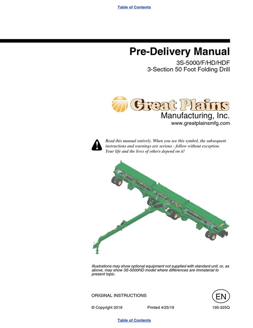
Pre-Delivery Manual
NTA3010, NTA3510 and ADC
No-Till Air Drill
and Air Drill Cart
Read the pre-delivery manual entirely. When you see this symbol, the
subsequent instructions and warnings are serious - follow without exception.
Your life and the lives of others depend on it!
Cover illustration may show optional equipment not supplied with standard
units.
!
28450
NTA3010, NTA3510 and ADC Cover iii
04/14/2022 Cover 160-220M
© Copyright Define Cop.History All rights Reserved
Great Plains Manufacturing, Inc. provides this publication “as is” without warranty of any kind, either expressed or implied. While every precaution has been
taken in the preparation of this manual, Great Plains Manufacturing, Inc. assumes no responsibility for errors or omissions. Neither is any liability assumed
for damages resulting from the use of the information contained herein. Great Plains Manufacturing, Inc. reserves the right to revise and improve its products
as it sees fit. This publication describes the state of this product at the time of its publication, and may not reflect the product in the future.
Trademarks of Great Plains Manufacturing, Inc. include: AccuShot, Max-Chisel, Row-Pro,
Singulator Plus, Short Disk, Swath Command, Terra-Tine, Ultra-Chisel, and X-Press.
Registered Trademarks of Great Plains Manufacturing, Inc. include: Air-Pro, Clear-Shot, Discovator, Great Plains, Land Pride, MeterCone,
Nutri-Pro, Seed-Lok, Solid Stand, Terra-Guard, Turbo-Chisel, Turbo-Chopper, Turbo-Max, Turbo-Till, Ultra-Till, Whirlfilter, and Yield-Pro.
Brand and Product Names that appear and are owned by others are trademarks of their respective owners.
Printed in the United States of America
Table of Contents
Important Safety Information.................................................1
Introduction.............................................................................4
Implements Covered .........................................................4
Document Family .......................................................4
Definitions...................................................................4
Further Assistance.............................................................4
Air Cart Pre-Delivery...............................................................5
Air Cart Preparation...........................................................5
Cart Assembly Summary............................................5
Tools Required ...........................................................5
ADC2350 Cart Pre-Assembly Checklist .....................5
Unload Air Cart...........................................................6
Lift Air Cart on Truck ..................................................7
Locate Parts ......................................................................7
Install Wheels ....................................................................8
Cart Closeout.....................................................................8
Install Cab Components ....................................................8
Air Drill Assembly...................................................................9
Drill Preparation.................................................................9
Drill Assembly Summary ............................................9
Tools Required ..................................................................9
Drill Pre-Assembly Checklist .............................................9
Assembly Area ................................................................10
Locate Parts ....................................................................11
Unload Truck ...................................................................11
Drill Assembly..................................................................12
Wing to Frame..........................................................12
Rockshaft to Frame ..................................................12
Gauge Wheel Arms to Wings...................................13
Mount Rockshaft Wheels.................................................14
Mount Front Gauge Wheels ............................................14
Assemble Lift-Assist-Wheel Arms ............................15
Install Lift Hydraulics ................................................17
Route Hydraulic Hoses ............................................19
Setup......................................................................................20
Hitch Cart to Implement...................................................20
Hitching ADC2350 Cart............................................20
Hitching ADC2220 Cart............................................20
Make Electrical Connections ...........................................21
ADC2350 Electrical Connections .............................21
ADC2220 Electrical Connection...............................21
Make Hydraulic Connections...........................................22
Charging Hydraulics ........................................................23
Charging Lift Hydraulics ...........................................23
Charging Fold Hydraulics.........................................25
Level Frame ....................................................................26
Level Frame Side to Side .........................................26
Front to Back Level ..................................................28
Install Distribution Towers ...............................................29
Tower Positioning.....................................................29
Install Primary Seed Hoses .............................................31
Install Secondary Seed Hoses ........................................32
Install Lift Switch (ADC2350 Only) ...........................38
Install Press Wheels.................................................39
Install Options ..........................................................39
Appendix ...............................................................................40
Torque Chart ...................................................................40
Parts Lists........................................................................41
Drill Parts..................................................................41
Parts Supplied with ADC2220 Air Cart.....................42
Parts Supplied with ADC2350 Air Cart.....................42
Abbreviations...................................................................43
2022-04-14 Table of Contents 160-220M
NTA3010, NTA3510 and ADC Table of Contents 1
Important Safety Information
Read “Important Safety Information” in the Operator
Manual for both air cart and air drill.
Look for Safety Symbol
The SAFETY ALERT SYMBOL indicates there is a
potential hazard to personal safety involved and extra
safety precaution must be taken. When you see this
symbol, be alert and carefully read the message that
follows it. In addition to design and configuration of
equipment, hazard control and accident prevention are
dependent upon the awareness, concern, prudence and
proper training of personnel involved in the operation,
transport, maintenance and storage of equipment.
Be Aware of Signal Words
Signal words designate a degree or level of hazard
seriousness.
DANGER indicates an imminently hazardous situation
which, if not avoided, will result in death or serious injury.
This signal word is limited to the most extreme situations,
typically for machine components that, for functional
purposes, cannot be guarded.
WARNING indicates a potentially hazardous situation
which, if not avoided, could result in death or serious
injury, and includes hazards that are exposed when
guards are removed. It may also be used to alert against
unsafe practices.
CAUTION indicates a potentially hazardous situation
which, if not avoided, may result in minor or moderate
injury. It is also used to alert against unsafe practices.
Review Operating Information
s Review Operator Manuals included with drill and cart.
s Read and understand “Safety Decals” in Operator
Manuals.
s Read all instructions noted on the decals.
!
!DANGER
!
WARNING
!CAUTION
2022-04-14 Table of Contents 160-220M
NTA3010, NTA3510 and ADC Table of Contents Important Safety Information 2
Prepare for Emergencies
s Be prepared if a fire starts
s Keep a first aid kit and fire extinguisher handy.
s Keep emergency numbers for doctor, ambulance, hospital
and fire department near phone.
Avoid High Pressure Fluids
Escaping fluid under pressure can penetrate the skin,
causing serious injury.
s Avoid the hazard by relieving pressure before disconnecting
hydraulic lines.
s Use a piece of paper or cardboard, NOT BODY PARTS, to
check for suspected leaks.
s Wear protective gloves and safety glasses or goggles when
working with hydraulic systems.
s If an accident occurs, seek immediate medical attention
from a physician familiar with this type of injury.
Check for Overhead Lines
Drill markers contacting overhead electrical lines can
introduce lethal voltage levels on implement and tractor
frames. A person touching almost any metal part can
complete the circuit to ground, resulting in serious injury
or death. At higher voltages, electrocution can occur
without direct contact.
s Avoid overhead lines during marker installation, auger
seed loading/unloading and marker operations.
911
NTA3010, NTA3510 and ADC Table of Contents Important Safety Information 3
2022-04-14 Table of Contents 160-220M
Transport Machinery Safely
Maximum transport speed for assembly and/or cart is 20
mph (32 kph). Some rough terrains require a slower
speed. Sudden braking can cause a towed load to
swerve and upset.
s Do not exceed 20 mph (32 kph). Never travel at a speed
which does not allow adequate control of steering and
stopping. Reduce speed if towed load is not equipped with
brakes.
s Comply with national, regional and local laws.
s Follow your tractor manual recommendations for
maximum hitch loads. Insufficient weight on tractor
steering wheels will result in loss of control.
s Carry reflectors or flags to mark implements in case of
breakdown on the road.
s Keep clear of overhead power lines and other obstructions
when transporting. Refer to transport dimensions under
“Specifications and Capacities” in Operator manual.
Practice Safe Maintenance
s Understand procedure before doing work. Use proper tools
and equipment. Refer to this manual for additional
information.
s Work in a clean, dry area.
s Put tractor in park, turn off engine, and remove key before
performing maintenance.
s Make sure all moving parts have stopped and all system
pressure is relieved.
s Disconnect battery ground cable (-) before servicing or
adjusting electrical systems or before welding on
implements.
s Inspect all parts. Make sure parts are in good condition and
installed properly.
s Remove buildup of grease, oil or debris.
s Remove all tools and unused parts from implements before
operation.
OFF
2022-04-14 Table of Contents 160-220M
NTA3010, NTA3510 and ADC Table of Contents 4
Introduction
Great Plains Manufacturing wants you to be satisfied
with any new machine delivered by the Great Plains
Trucking network. To ease the assembly task and
produce a properly working machine, read this entire
manual before setting up new equipment.
Implements Covered
•30 and 35-foot No-Till Air Drills:
NTA3010-361030-foot, 36-row, 10in (25cm)
NTA3010-487530-foot, 48-row, 7.5in (19cm)
NTA3510-401035-foot, 40-row, 10in (25.4cm)
NTA3510-557535-foot, 55-row, 7.5in (19cm)
•When used with Air Drill Cart:
ADC2220Dual 110bu, basic monitor
ADC2350Dual 175bu, Intelli-ag monitor
Note:Do not commence assembly unless the cart is
also at hand. Some drill components are
shipped with the cart.
These pre-delivery instructions include hitching to the air
cart. The drill is intended to be towed by the cart, and
cannot be towed alone.
This model drill is not compatible with the “pull behind”
ADC2350B cart. These instructions do not cover
integration with the ADC1150 or ADC2250 carts.
Document Family
160-220M NTA30/35 Pre-Delivery (this manual)
160-219M-A NTA-3010/3510 Operator Manual
160-219P NTA-3010/3510 Parts Manual
For ADC2350:
167-085M ADC2350/2350B Operator Manual
167-085P ADC2350/2350B Parts Manual
167-085B ADC2350/2350B Seed Rate Manual
110011445 DICKEY-john Air Cart Operator
110011460 NTA QUICKSTART GUIDE
For ADC2220:
167-073M ADC2220 Operator/Seed Rate Manual
167-073P ADC2220 Parts Manual
167-088M ADC2220 Pre-Delivery Manual
Definitions
Paragraphs in this format present a crucial point of information
related to the current topic.
Read and follow the directions to:
- remain safe and
- avoid serious damage to equipment.
Note:Paragraphs in this format provide useful
information related to the current topic.
“Left” and “Right” are facing in the
direction of machine travel. An
orientation rose in the line art
illustrations shows the directions of:
Up, Back, Left, Down, Front, Right.
Further Assistance
Great Plains Manufacturing, Inc. wants you to be
satisfied with your new product. If for any reason you do
not understand any part of this manual or are otherwise
dissatisfied, please contact:
Great Plains Service Department
1525 E. North St.
P.O. Box 5060
Salina, KS 67402-5060
Or go to www.greatplainsag.com and follow the contact
information at the bottom of your screen for our service
department.
to &
to
callouts identify components in the currently
referenced Figure or Figures.
to
call-outs reference new parts from the lists starting
on page 41, and are consistent across all pages.
Descriptions match those on the cartons, bags or
item tags, as well the current Parts Manual.
U
D
F
B
L
R
1 9
a z
11 93
2022-04-14 Table of Contents 160-220M
NTA3010, NTA3510 and ADC Table of Contents 5
Air Cart Pre-Delivery
Air Cart Preparation
For ADC2350 pre-delivery, continue below at “ADC2350
Pre-Delivery”.
For ADC2220 pre-delivery manual, complete the tasks in
manual 167-088M, and then resume steps in this manual
at “Install Cab Components” on page 8.
ADC2350 Pre-Delivery
Step-by-step instructions for assembling the ADC2350 air
cart begin on page 8. Before commencing work, review
the Tools Required and Pre-Assembly Checklist to make
sure you have all necessary parts and equipment.
The ADC2350 is shipped via flat bed truck. It is the
dealer’s responsibility to unload the new machine. Unload
all equipment before beginning assembly.
Attempt no assembly work with air cart still on truck.
The general sequence is:
Cart Assembly Summary
a. Remove all items except cart from truck.
Note:Many items shipped with the ADC2350 cart, or
shipped on the truck carrying the cart, are
installed on the NTA-3010/3510 implement.
b. Lift air cart above truck, and pull truck away.
c. Lower air cart.
d. Install wheels.
e. Spot air cart for final implement assembly.
These next steps are performed during drill pre-delivery
tasks:
f. Prepare cart hitch.
g. Hitch to air drill implement.
Tools Required
•A tractor adequate for positioning the air cart. Tractor
requirements for drill pre-delivery are more
demanding (see drill Operator manual).
•A large hoist or two forklifts, with a net lifting capacity
of 9000 pounds (4082 kg).
•Jacks, jack stands or blocks, and safety chain.
•General hand tools.
ADC2350 Cart Pre-Assembly Checklist
Read and understand “Important Safety
Information” on page 1 before assembling.
Have at least four people for unloading.
Make sure the assembly area is level and free of
obstructions (preferably an open concrete area).
Have all major components accounted for.
Have a copy of the air cart Parts Manual (167-085P)
on hand. If unsure of proper placement or use of any
part or fastener, refer to the parts manual.
Check that all working parts are moving freely, bolts
are tight, and cotter pins are spread.
Check that all factory-applied safety labels and
reflectors are correctly located and legible. Replace
if improperly located or damaged. Refer to Safety
Decals, in the “Important Safety Information”
section of the drill Operator’s Manual.
Inflate tires to recommended pressure as listed in
the Operator manual.
An Operator Manual is provided with the new machine.
Read and understand “Important Safety Information”
and “Operating Instructions” in the Operator Manual
before assembling the machine. As a reference, keep
the Operator Manual on hand while assembling.
2022-04-14 Table of Contents 160-220M
NTA3010, NTA3510 and ADC Table of Contents Air Cart Pre-Delivery 6
Unload Air Cart
The ADC2220 or ADC2350B is normally ordered with an
NTA-3010/3510 drill, and delivered on two or more
flatbed trucks. Un-installed components may be on the
air cart truck, the drill truck (single-truck delivery), or on a
separate truck.
Note:The air cart is loaded for lift delivery.
Hoist is not recommended.
Do not attempt dock unload.
Hopper damage is likely if hoisting is attempted.
Refer to Figure 1
1. Have the truck parked where it can be driven out
from under an elevated air cart, and where two fork
lifts can approach the cart from each side.
2. Use fork lifts or hoists to remove everything except
the air cart from the truck. This will include wheels for
the air cart, and may include crates of drill parts and
un-installed options. Do not install any components
on the air cart while still on the truck.
Figure 1
Air Cart on Truck
28207
Have at least four people available for the lift:
- a qualified operator for each forklift,
- an observer to monitor side-to-side level, and
- the truck driver.
Establish and practice commands for the observer to signal
each operator for lift, stop, drive, lower, as well as
emergency procedures. If these operators have not previously
performed a team lift, have them practice simultaneous lift,
face-to-face with no load.
NTA3010, NTA3510 and ADC Table of Contents Air Cart Pre-Delivery 7
2022-04-14 Table of Contents 160-220M
Lift Air Cart on Truck
Use two fork lifts, each rated for at least 9000 pounds
(4082 kg) for ADC2350. Have two cargo straps at hand.
Spread the forks on each lifter as wide as possible. Have
each lift approach the cart near the ladder.
Refer to Figure 2
1. Place the forks under the lower side frame tubes, on
either side of the ladder, and as far forward on the air
cart as possible.
This places the front fork /F\ as close to the tongue
joint as possible, and places the back fork /B\ as
close to the ladder as possible.
2. Secure both forks to the frame tube with cargo
straps.
3. Lift the cart about a foot (30cm).
4. Signal the driver to pull the truck away.
5. Lower the cart to the ground.
Locate Parts
Review the Parts Lists beginning on page 39. Determine
which crates or cartons contain the items.
Figure 2
Air Cart Lift Points
28452
B
F
U
D
B
F
With typical fork spreads, the load is still heavier at the front
end of the cart.
2022-04-14 Table of Contents 160-220M
NTA3010, NTA3510 and ADC Table of Contents Air Cart Pre-Delivery 8
Install Wheels
Refer to Figure 3
Wheels are supplied as mirror-image assemblies,
mounted for left- hand vs. right-hand use. The wheel
assemblies use identical tires and rims, each side
mounted with the valve stem to the outside. The figure
shows tread orientations suggested by Great Plains.
If the customer’s preference is to reverse the tread
pattern at the ground, the wheels may be mounted on
the opposite cart side. Do not merely invert the wheels,
or the valve stems will be to the inside.
1. Jack up the rear end of the cart, and support the rear
of the frame with jack stands.
2. Remove and save the nuts (20 total):
803-183C NUT HEX FLANGE 3/4-16 PLT
from the rear hub assemblies.
3. Select one:
168-381K 23.5/55-26 TIRE/20-10BLT WL LH
Mount the wheel , valve stem side out, on the left-
hand side of the cart. Secure with ten nuts .
4. Select one:
168-380K 23.5/55-26 TIRE/20-10BLT WL RH
Mount the wheel , valve stem side out, on the
right-hand side of the cart. Secure with ten nuts .
5. Lower rear end of cart to ground.
Cart Closeout
Verify that the cart has the correct sprocket for the drill.
See “Cart Drive System” in the Air Cart Operator
manual.
Install Cab Components
If the customer tractor is available, install the eed Monitor
in the tractor cab. This is described under “Preparation
and Setup” in the Air Cart Operator manual.
Figure 3
Air Cart Transport Wheels
28453
91 88
87
91
88
88
91
87
87
91
2022-04-14 Table of Contents 160-220M
NTA3010, NTA3510 and ADC Table of Contents 9
Air Drill Assembly
Drill Preparation
Step-by-step instructions for assembling the drill begin on
page 5. Before commencing work, review the Tools
Required and Pre-Assembly Checklist to make sure you
have all necessary parts and equipment.
The drill is shipped via flat bed truck. It is the dealer’s
responsibility to unload the new machine. Unload all
equipment before beginning assembly.
Attempt no assembly work with drill still on truck.
The general sequence is:
Drill Assembly Summary
a. Hoist sub-assemblies off truck.
b. Attach wings to frame.
c. Attach rockshaft, wing gauge wheels.
Assemble and attach read lift-assist arms.
d. Install hydraulics.
e. Hitch air cart.
f. Charge hydraulic system.
g. Level frame.
h. Install towers.
i. Cut and install hoses.
j. Install height switch (ADC2350) and press wheels.
k. Install other standard and optional components that
were not factory-installed, such as markers and
blockage detectors.
Tools Required
•A tractor of sufficient size and horsepower with at
least two remote hydraulic circuits. Refer to
“Specifications and Capacities” in the drill
Operator’s Manual.
•A hoist or forklifts with a total capacity of 11,000
pounds (4990 kg) for removing components from
truck and for assembly.
•Jacks, jack stands or blocks, and safety chain.
•General hand tools, including snap ring pliers.
•About 14 gallons (53 liters) of hydraulic fluid to
charge the cart and implement systems.
Drill Pre-Assembly Checklist
Read and understand “Important Safety
Information” on page 1 before assembling.
Have at least two people on hand while assembling.
Have all major components accounted for. Have all
fasteners and pins shipped with drill.
Have a copy of the drill Parts Manual (160-219P) on
hand. If unsure of proper placement or use of any
part or fastener, refer to the parts manual.
Check that all working parts are moving freely, bolts
are tight, and cotter pins are spread.
Check that all factory-applied safety labels and
reflectors are correctly located and legible. Replace
if improperly located or damaged. Refer to Safety
Decals, in the “Important Safety Information”
section of the drill Operator’s Manual.
Inflate tires to recommended pressure as listed in
the Operator manual.
An Operator Manual is provided with the new machine.
Read and understand “Important Safety Information”
and “Operating Instructions” in the operator’s manual
before assembling the machine. As a reference, keep
the Operator Manual on hand while assembling.
2022-04-14 Table of Contents 160-220M
NTA3010, NTA3510 and ADC Table of Contents Air Drill Assembly 10
Assembly Area
Choose an assembly location with ample room. Allowing
room for turns, the complete assembly of tractor, drill and
air cart may require a space with a:
length over 100 feet (30m) and
width of 45 feet (14m) without markers, or
width of 80 feet (24m) with markers.
Make sure the assembly area is level and free of
obstructions (preferably an open concrete area).
Check for overhead lines, particularly if the drill will have
markers. The air cart requires at least 12ft (7.6m) vertically,
and more if auger deployment is contemplated.
Crushing hazard. You may be severely injured or killed by the
implement frames if they fall. Always support the frame
sections with jack stands or blocks before working on
implements raised off the ground.
Obey all safety instructions from lifting equipment
manufacturer. Do not walk or place any part of the body under
the raised sections. Be sure shipping stands are securely
attached prior to lifting. Be sure lifting equipment has enough
capacity.
Figure 4
Assembly Clearances
(without markers)
28455
70 ft
21m
F
B
R
L
45 ft
14m
NTA3010, NTA3510 and ADC Table of Contents Air Drill Assembly 11
2022-04-14 Table of Contents 160-220M
Locate Parts
Review the Parts Lists beginning on page 39. Determine
which crates or cartons contain the items.
Unload Truck
The NTA-3010/3510 is normally ordered with an air cart,
and delivered on two flatbed trucks. Un-installed compo-
nents may be on the drill truck (single-truck delivery), the
air cart truck, or on a separate truck.
Note: The heaviest sub-assemblies may weigh as much
as 11,000 pounds (4900 kg).
1. Remove the frame sections from the truck and place
them on the ground. The wings are stacked together.
2. Disconnect the wings. Support top wing with the
hoist or forklift and remove the u-bolts that hold the
top-wing-shipping stands to the bottom wing. Leave
the shipping stands on the wings.
3. Carefully lift the top wing off the bottom wing and
place it on solid, level ground or concrete if available.
4. With the shipping stands still bolted to each section,
move the center section and left-hand wing to the
center of assembly area.
2022-04-14 Table of Contents 160-220M
NTA3010, NTA3510 and ADC Table of Contents Air Drill Assembly 12
Drill Assembly
Wing to Frame
Start with the left-hand wing.
Refer to Figure 5
1. Check that the pivot bushings:
890-011C BUSHING SPINDLE 1 1/2X1 1/4X1
are in place in center-section pivot tubes.
2. At each wing clevis , drive out and save:
805-249C PIN ROLL 3/8 X 2 PLT
then remove and save two:
160-201H WING PIVOT PIN WELDMENT
3. Align wing clevises with center-section pivot tubes
. Re-insert pivot pins . Secure with roll pins .
4. Repeat step 1 through step 3 for right-hand wing
Rockshaft to Frame
Refer to Figure 6
1. Check that the pivot bushings:
890-011C BUSHING SPINDLE 1 1/2X1 1/4X1
are in place in the three rockshaft pivot tubes.
2. At each center section clevis , drive out and save:
805-249C PIN ROLL 3/8 X 2 PLT
then remove and save three:
160-201H WING PIVOT PIN WELDMENT.
3. With hoist or forklift move the rockshaft:
161-074H NTA 35’ ROCKSHAFT WELDMENT
to the front of the implement and align each
rockshaft pivot tube with the center-section clevis.
4. When the holes are aligned, insert pivot pins and
secure with roll pins .
Figure 5
Wing to Frame Assembly
16222
61
1
61
16
53
U
D
F
B
L
R
61
1
53
16
1
61 16 53
Figure 6
Rockshaft to Frame Assembly
16223
U
D
F
B
L
R
61
18
16
53
1
1
1
Crushing hazard. You may be severely injured or killed by the
rockshaft if it falls. Be certain the rockshaft is securely
supported by a forklift or hoist.
61
1
53
16
18
16
53
NTA3010, NTA3510 and ADC Table of Contents Air Drill Assembly 13
2022-04-14 Table of Contents 160-220M
Gauge Wheel Arms to Wings
Start with the right-hand wing.
Refer to Figure 7
1. Check that the pivot bushings:
890-011C BUSHING SPINDLE 1 1/2X1 1/4X1
are in place in pivot tubes on the gauge-wheel arms.
2. At each wing clevis , drive out and save:
805-249C PIN ROLL 3/8 X 2 PLT
then remove and save two:
160-201H WING PIVOT PIN WELDMENT
3. Use forklift or hoist to move the gauge-wheel arm
161-076H NTA WING GAUGE WHEEL WLDMNT RH
to the front of the right-hand wing.
Determine which gauge-wheel arm is for the current wing by
looking at the cylinder lug on the wheel arm. When standing
behind the arm pivot tubes, the lug will be to the outside (right
of center for the right-hand wing, and left of center for left-
hand wing).
4. Align wing clevis and arm pivot tubes. When in
place, right-hand insert pivot pins and secure with
roll pins .
5. Repeat step 1 through step 4 for left-hand wing
gauge wheel arm:
161-077H NTA WING GAUGE WHEEL WLDMNT LH
Figure 7
Wing Gauge Wheel to Frame
16424
U
D
F
B
L
R
61
19
16
53
Cylinder
Lug to
Outside
1
61
1
53
16
19
16
53
20
2022-04-14 Table of Contents 160-220M
NTA3010, NTA3510 and ADC Table of Contents Air Drill Assembly 14
Mount Rockshaft Wheels
Start with the left-hand side of the rockshaft.
Refer to Figure 8
1. At rockshaft hubs, remove and save 12 wheel bolts:
802-399C HFS 1/2-20X1 1/2 GR5
and two:
152-215D WHEEL REINFORCING RING
Do not mix bolts. Although all wheel bolts are 12-20 thread,
rockshaft wheel bolts are different from wing gauge wheel
bolts and lift-assist wheel bolts .
2. Forklift or hoist rockshaft. Place wheels on hubs:
155-012K TRANSPORT WHEEL & TIRE ASSY
on the rockshaft wheel hubs.
Bolt wheels with edge of center dish in toward hub as shown in
Figure 8. Otherwise, wheels will be too wide.
3. Place a reinforcing ring on each wheel . Insert
bolts and tighten to torque specification.
4. Repeat step 1 through step 3 for the right-hand side
of the rockshaft.
Mount Front Gauge Wheels
Start with the left-hand gauge wheel.
Refer to Figure 9
1. At the two gauge wheel hubs, remove and save 12
gauge wheel bolts:
802-104C BOLT WHEEL 1/2-20X1 90-DEG
Do not mix bolts. Although all wheel bolts are 12-20 thread,
wing gauge wheel bolts and rockshaft wheel bolts are
not identical.
2. Support wing gauge-wheel arms with jack. Mount
wheels on hubs.
Bolt wheels with edge of center dish in toward hub as shown in
Figure 9. Otherwise, wheels will be too wide.
3. Insert bolts and tighten to torque specification.
4. Repeat step 1 through step 3 for the right-hand side
of the rockshaft.
Figure 8
Rockshaft Wheel Mounting
16199
39
15
14
39
14
39
37 37
15
14 15
39
Figure 9
Wing Gauge Wheel Mounting
16199
37
15
37
37 39
15
37
NTA3010, NTA3510 and ADC Table of Contents Air Drill Assembly 15
2022-04-14 Table of Contents 160-220M
Assemble Lift-Assist-Wheel Arms
Un-Stow Arms
Rear parallel arms are folded forward for shipment.
Start with the left-hand assembly.
Refer to Figure 11
1. Remove and save top nut, lock washer, spacer and
bolt:
803-031C NUT HEX 1-8 PLT
804-027C WASHER LOCK SPRING 1 PLT
161-246D NTA CASTER ARM SPACER TUBE
802-638C HHCS 1-8X12 1/4 GR8
These hold the folded arms on implement.
2. Use forklift or hoist to unfold arms and caster
mounting.
3. Insert the spacer in upper parallel arm and
secure upper arm to implement with saved bolt ,
lock washer and nut .
4. Repeat step 1 through step 3 for the right-hand lift-
assist assembly.
Mount Wheels on Casters
Refer to Figure 11
There are two assemblies and four wheels.
1. At the caster assemblies:
161-116K NTA35 DUAL CASTER WHEEL ASSY
remove and save 12 caster wheel bolts:
802-104C BOLT WHEEL 1/2-20X1 90-DEG
Do not mix bolts. Although all wheel bolts are 12-20 thread,
lift-assist caster wheel bolts and rockshaft wheel bolts
are not identical.
2. Support caster weldments with hoist. Mount wheels
on hubs.
Bolt wheels with edge of center dish in toward hub as shown in
Figure 11. Otherwise, wheels will be too wide.
3. Insert bolts and tighten to torque specification.
Figure 10
Rear Lift Assist Arm
28456
43
30
46
41
25
43
46
30
41
30 25
41
46 43
Figure 11
Lift-Assist Wheel Mounting
16199
37
15
24
24
37
37 39
15
37
2022-04-14 Table of Contents 160-220M
NTA3010, NTA3510 and ADC Table of Contents Air Drill Assembly 16
Install Casters in Arms
Start with the left-hand lift-assist assembly. The casters
are identical (not supplied in left-hand/right-hand
variants).
Refer to Figure 12
1. At a caster assembly , remove and save two sets:
802-034C HHCS 1/2-13X1 1/4 GR5
804-015C WASHER LOCK SPRING 1/2 PLT
and one:
161-231D NTA CASTER RETAINER CAP
2. Use forklift or hoist to raise lift-assist arm caster
mount . Make sure thrust washer is still on
caster assembly . Roll caster under mount, and
lower mount onto caster.
3. Place retainer cap back on top of caster shaft.
Secure with bolts and lock washers . Tighten
to torque spec.
4. Repeat step 1 through step 3 for right-hand lift-
assist-wheel arm.
Figure 12
Rear Lift Assist Caster Install
28456
29
24
36
45
21
48
U
D
F
B
L
R
24
36
45
29
21 48
24
29
36 45
NTA3010, NTA3510 and ADC Table of Contents Air Drill Assembly 17
2022-04-14 Table of Contents 160-220M
Install Lift Hydraulics
Note:There are four different size cylinders supplied for
use with the NTA drill. Check part numbers and
bore sizes. Pin hardware may also be different for
rod and base ends of the same cylinder.
Install wing Gauge Wheel Cylinders
Start with the right-hand wing.
Refer to Figure 13
1. At the center section, until the wing gauge-wheel
cylinders. Select the right-hand cylinder:
810-221C CYL REP 4.25X12X1.5 ROD (TIE)
The gauge-wheel cylinders for the wings are labeled
414in bore re-phasing. The right-hand cylinder is the
one without the 161-112K depth-stop valve
assembly .
2. Remove and save the base-end pin hardware:
805-017C PIN COTTER 3/16 X 1 3/4 PLT
804-029C WASHER FLAT 1 SAE
805-239C PIN CLEVIS 1 X 3 5/16 HRD PLT
3. With the hydraulic ports facing up or inward, pin the
base end of the cylinder to the right-hand wing
eyebolt . Secure with clevis pin , washer
and cotter pin . Hoses are routed at step 7.
4. Remove and save the rod-end pin hardware:
805-017C PIN COTTER 3/16 X 1 3/4 PLT
804-029C WASHER FLAT 1 SAE
805-159C PIN CLEVIS 1 X 3 1/8 GR5 PLT
5. Pin the rod end of the cylinder to the right-hand
gauge wheel lug . Loosely hold in place with clevis
pin only. Leave rod end washer cotter pin
off, to ease the later task of hydraulic charging.
Figure 13
Right-Hand Gauge Wheel Cylinder
16425
52
47
49
56
49
47
51
1
22
U
D
F
B
L
R
Mounting cylinders incorrectly voids warranty and can cause
implement damage.
Install Wing Gauge Wheel Cylinders
56
23
49
47
52
56
22 52 47
49
49
47
51
56
1
52 47 49
2022-04-14 Table of Contents 160-220M
NTA3010, NTA3510 and ADC Table of Contents Air Drill Assembly 18
Refer to Figure 13 on page 17 and Figure 14
6. Select the left-hand gauge wheel cylinder, which is:
161-112K NTA DEPTH STOP VALVE ASSY and
810-221C CYL REP 4.25X12X1.5 ROD (TIE)
7. Remove and save the base-end pin hardware:
805-017C PIN COTTER 3/16 X 1 3/4 PLT
804-029C WASHER FLAT 1 SAE
805-239C PIN CLEVIS 1 X 3 5/16 HRD PLT
8. With the depth stop on top of the cylinder, pin the
base end of the cylinder to the left-hand wing
eyebolt . Secure with clevis pin , washer and
cotter pin . Hoses are routed at step 7.
9. Remove and save the rod-end pin hardware:
805-017C PIN COTTER 3/16 X 1 3/4 PLT
804-029C WASHER FLAT 1 SAE
805-159C PIN CLEVIS 1 X 3 1/8 GR5 PLT
10. Pin the rod end of the cylinder to the left-hand
gauge wheel lug . Loosely hold in place with clevis
pin only. Leave rod end washer cotter pin
off, to ease the later task of hydraulic charging.
Install Lift-Assist Cylinders
Start with the left-hand caster assembly. Cylinders are
identical for both sides.
Refer to Figure 13
1. At the center section, untie the lift-assist cylinders.
Select one:
810-333C CYL REP 4.5X12X1.5 ROD 22.25L
The gauge-wheel cylinders for the wings are labeled
412in bore re-phasing.
2. Remove and save the base-end pin hardware:
805-017C PIN COTTER 3/16 X 1 3/4 PLT
804-029C WASHER FLAT 1 SAE
805-124C PIN CLEVIS 1 X 3 11/16 GR5 PLT
3. With the cylinder ports oriented up, pin the base end
of the lift-assist cylinder to the top lug , using a
pin , washer and cotter key .
4. Locate, or remove and save the rod end hardware:
161-211D REAR LIFT CASTER CYLINDER PIN
161-221D SPACER 1.5X1.032X1.5
804-029C WASHER FLAT 1 SAE
805-017C PIN COTTER 3/16 X 1 3/4 PLT
5. Pin the rod end of the lift-assist cylinder to the eye-
bolt using the pin and spacers . Hold the
washer and cotter pins aside until after
hydraulic charging. Hoses are routed at step 7.
6. Repeat step 1 through step 5 for right-hand lift-
assist-wheel arm.
Figure 14
left-hand Gauge Wheel Cylinder
16220
23
2
56
23
56
49
47
52
56
2 52 47
49
49
47
51
56
1
52 47 49
Figure 15
Lift-Assist Cylinder
28459
50
47
49 57
3
28
27
47
33
49
U
D
F
B
L
R
57
49
47
50
57 3
50 47 49
27
28
47
49
3 27 28
47 49

This manual suits for next models

1

Other GREAT PLAINS Farm Equipment manuals

GREAT PLAINS Turbo Max 3.0M TM User manual

GREAT PLAINS

GREAT PLAINS Turbo Max 3.0M TM User manual

GREAT PLAINS PL5700 User manual

GREAT PLAINS

GREAT PLAINS PL5700 User manual

GREAT PLAINS NTA607HD User manual

GREAT PLAINS

GREAT PLAINS NTA607HD User manual

GREAT PLAINS 7000 Series Guide

GREAT PLAINS

GREAT PLAINS 7000 Series Guide

GREAT PLAINS PL5700 User manual

GREAT PLAINS

GREAT PLAINS PL5700 User manual

GREAT PLAINS BD7600 User manual

GREAT PLAINS

GREAT PLAINS BD7600 User manual

GREAT PLAINS PL5700 User manual

GREAT PLAINS

GREAT PLAINS PL5700 User manual

GREAT PLAINS MC5109 Max-Chisel User manual

GREAT PLAINS

GREAT PLAINS MC5109 Max-Chisel User manual

GREAT PLAINS VT1100 Turbo Max User manual

GREAT PLAINS

GREAT PLAINS VT1100 Turbo Max User manual

GREAT PLAINS Turbo Max 1800TM User manual

GREAT PLAINS

GREAT PLAINS Turbo Max 1800TM User manual

GREAT PLAINS 3P605NT User manual

GREAT PLAINS

GREAT PLAINS 3P605NT User manual

GREAT PLAINS NO-TILL Air DRILL User manual

GREAT PLAINS

GREAT PLAINS NO-TILL Air DRILL User manual

GREAT PLAINS 2S-2600 User manual

GREAT PLAINS

GREAT PLAINS 2S-2600 User manual

GREAT PLAINS Yield-Pro Air-Pro YP625PD User manual

GREAT PLAINS

GREAT PLAINS Yield-Pro Air-Pro YP625PD User manual

GREAT PLAINS 1007NT User manual

GREAT PLAINS

GREAT PLAINS 1007NT User manual

GREAT PLAINS RC2515 User manual

GREAT PLAINS

GREAT PLAINS RC2515 User manual

GREAT PLAINS 5109 User manual

GREAT PLAINS

GREAT PLAINS 5109 User manual

GREAT PLAINS 3P1006NT User manual

GREAT PLAINS

GREAT PLAINS 3P1006NT User manual

GREAT PLAINS HT1100-35 User manual

GREAT PLAINS

GREAT PLAINS HT1100-35 User manual

GREAT PLAINS 706NT User manual

GREAT PLAINS

GREAT PLAINS 706NT User manual

GREAT PLAINS 3P1006NT Guide

GREAT PLAINS

GREAT PLAINS 3P1006NT Guide

GREAT PLAINS TSF1080 User manual

GREAT PLAINS

GREAT PLAINS TSF1080 User manual

GREAT PLAINS SPARTAN II User manual

GREAT PLAINS

GREAT PLAINS SPARTAN II User manual

GREAT PLAINS TCN5107 User manual

GREAT PLAINS

GREAT PLAINS TCN5107 User manual

Popular Farm Equipment manuals by other brands

Honeybee AirFlex SDX quick start guide

Honeybee

Honeybee AirFlex SDX quick start guide

Avantco 600 Series Operator's manual

Avantco

Avantco 600 Series Operator's manual

Tube-Line TL60LSV Operator's manual

Tube-Line

Tube-Line TL60LSV Operator's manual

Eton TS18 Assembly instructions

Eton

Eton TS18 Assembly instructions

Midwest Mid-Tech Legacy 2000 user guide

Midwest

Midwest Mid-Tech Legacy 2000 user guide

Challenger 660B Service manual

Challenger

Challenger 660B Service manual

Tru-Turf SR72 SPORTS manual

Tru-Turf

Tru-Turf SR72 SPORTS manual

Hagie DTS 10 Operator's manual

Hagie

Hagie DTS 10 Operator's manual

LEMKEN Albatros 9 operating instructions

LEMKEN

LEMKEN Albatros 9 operating instructions

Raven VSN Operation manual

Raven

Raven VSN Operation manual

McHale F5000 RE-ASSEMBLY INSTRUCTIONS

McHale

McHale F5000 RE-ASSEMBLY INSTRUCTIONS

Raven SmarTrax installation manual

Raven

Raven SmarTrax installation manual

Goldacres G6 Crop Cruiser 2 Series Software update

Goldacres

Goldacres G6 Crop Cruiser 2 Series Software update

Kellands AGRIBUGGY 1000 Operator's instruction manual

Kellands

Kellands AGRIBUGGY 1000 Operator's instruction manual

BSL Strautmann Sherpa 1201 Translation of the original operating instructions

BSL

BSL Strautmann Sherpa 1201 Translation of the original operating instructions

aivituvin AIR09-B manual

aivituvin

aivituvin AIR09-B manual

Digga SLASHA Operator's manual

Digga

Digga SLASHA Operator's manual

LOFTNESS 61G4 Series Owner's manual and parts book

LOFTNESS

LOFTNESS 61G4 Series Owner's manual and parts book

manuals.online logo
manuals.online logoBrands
  • About & Mission
  • Contact us
  • Privacy Policy
  • Terms and Conditions

Copyright 2025 Manuals.Online. All Rights Reserved.