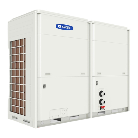
Gree B Series User manual

Service Manual
Change for life
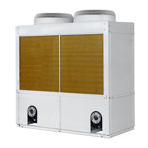
B series modular air-cooled scroll chiller (heat pump)
T1/ R410A /50Hz
Thank you for choosing commercial air conditioners.Please
read this Owner’ s Manual carefully before operation and
If you have lost the Owner's Manual, please contact the
local agent or visit www.gree.com or send an email to

Contents
PRODUCT ........................................................................................................3
1 Introduction ....................................................................................................3
1.1 Lineup.....................................................................................................3
1.2 Nomenclature .........................................................................................3
1.3 Product features .....................................................................................4
1.4 Nominal operating conditions..................................................................4
1.5 Operation range......................................................................................5
2 Unit performance curves................................................................................5
3 Working principle ...........................................................................................6
4 Techinical parameters list...............................................................................6
4.1 Electrical parameters ..............................................................................6
4.2 Performance parameters table................................................................7
4.3 Scope of supply ......................................................................................8
DESIGN AND SELECTION.............................................................................10
UNIT CONTROL .............................................................................................15
1 Schematic diagram ......................................................................................15
2 Operation owchart......................................................................................17
2.1 Cooling .................................................................................................17
2.2 Heating .................................................................................................18
3 Key control logics.........................................................................................19
3.1 Cooling control......................................................................................19
3.2 Heating control......................................................................................19
3.3 Automatic anti-freezing operation..........................................................20
3.4 Control to the compressor.....................................................................20
3.5 Control to the fan ..................................................................................20
3.6 Control to the 4–way valve....................................................................20
3.7 Control to the water pump.....................................................................20
3.8 Control to the electronic expansion valve .............................................20
3.9 Protection..............................................................................................20

4 General introduction.....................................................................................21
4.1 Homepage ............................................................................................22
4.2 Menu page............................................................................................23
4.3 Introduction to the pop-up windows ......................................................24
4.4 Backlight ...............................................................................................24
5 Operation instructions ..................................................................................25
5.1 On/Off ...................................................................................................25
5.2 Functions ..............................................................................................26
5.3 Parameter .............................................................................................34
5.4 Information............................................................................................36
5.5 E-Clear .................................................................................................44
5.6 General.................................................................................................45
5.7 Setup of DIP switches on the motherboard...........................................48
6 Smart management system .........................................................................49
6.1 Long-distance monitoring/BMS interface ..............................................49
6.2 Network of the long-distance monitoring system...................................49
6.3 Hardware ..............................................................................................50
6.4 Model selection instructions..................................................................51
UNIT INSTALLATION......................................................................................54
1 Installation owchart ....................................................................................54
2 Preparations before installation....................................................................55
2.1 Precautions for installation....................................................................55
2.2 Importance of installation ......................................................................56
2.3 Selection of installation materials..........................................................57
3 Tools ............................................................................................................62
3.1 Cutting and nishing tools.....................................................................62
3.2 Measuring tools ....................................................................................62
4 Installation instructions.................................................................................64
4.1 Outline dimensions ...............................................................................64
4.2 precautions for installation ....................................................................65

4.3 Installation environment ........................................................................65
4.4 Installation and service space...............................................................65
4.5 Installation foundation...........................................................................66
4.6 Handling and lifting ...............................................................................66
4.7 Placement of the main unit ...................................................................67
5 Piping and insulation....................................................................................68
5.1 Installation of the water system.............................................................68
5.2 Requirements on piping ........................................................................70
5.3 Installation of the expansion tank..........................................................78
5.4 Installation of condensate pipes............................................................79
6 Electric wiring...............................................................................................81
6.1 Safety precautions ................................................................................81
6.2 Control concept.....................................................................................81
6.3 Specication of power supply................................................................83
6.4 Wiring of the electric control cabinet .....................................................84
6.5 Filed wiring............................................................................................86
6.6 Networking and wiring between units....................................................87
6.7 Electric wiring digram............................................................................89
6.8 Jumpers................................................................................................91
TEST OPERATION, TROUBLESHOOTING AND MAINTENANCE ................93
1 Commissioning ............................................................................................93
1.1 Flowchart of commissioning..................................................................93
1.2 Safety precautions for commissioning...................................................93
1.3 Preparation before commissioning........................................................93
1.4 Check before commissioning ................................................................94
1.5 Check for initial run ...............................................................................95
2 Troubleshooting ...........................................................................................97
2.1 View on errors.......................................................................................97
2.2 Error list ................................................................................................99
2.3 Errors identifying of systems...............................................................100
2.4 Flow chart of troubleshooting..............................................................102
2.5 Error identifying of controller ...............................................................107

3 Power distribution ......................................................................................109
3.1 Power distribution logic .......................................................................109
3.2 Introduction to the main electric element ............................................110
4 Replacement of main parts ........................................................................110
4.1 Brief introduction.................................................................................110
4.2 Replacement instructions....................................................................112
5 Routine maintenance .................................................................................120
5.1 Repairs to refrigerant leakage.............................................................120
5.2 Air removal..........................................................................................121
6 Exploded views and part lists.....................................................................122
7 Maintenance ..............................................................................................127
7.1 Requirements for maintenance ...........................................................127
7.2 Freeze protection in winter..................................................................129

1
SAFETY NOTICE
The following symbols are used in this document to alert the reader to potential of hazard.
WARNING indicates a potentially hazardous situation which, if not avoided, could result in damage
to the machine as well as death or serious injury.
CAUTION identies a hazard which could lead to minimal or moderate damage to the machine as
well as death or serious injury.
BAN indicates a potentially hazardous situation which, if not avoided, could result in death or
serious injury.
COMPLIANCE identies a hazard which could lead death or serious injury as well as damage to the
property.
PREFACE
Thank you for selecting Gree’s B series inverter modular air-cooled chiller (heat pump). Please read
this service manual carefully before installing and using the product and achieve operating effect. We
hereby instruct as below:
The Manual is applied to B series inverter modular air-cooled chiller (heat pump), specifying operation
safety requirements, basic principles and implementation approaches for construction fulfillment,
construction debug, after-sale maintenance and repairs. All works must be performed in accordance with
the relevant national (and local) safety requirements and User's Manual, which if not abided, could result
in potential damage to the air conditioner, and even serious injury or death.

2
Product
Product

3
Product
PRODUCT
1 Introduction
1.1 Lineup
Model
Cooling
capacity
Heating
capacity Power supply Refrigerant Diagram
kW kW
LSQWRF65VM/NaB-X 65 70
380-415VAC
3Ph 50Hz/60Hz R410A
LSQWRF130VM/NaB-X 130 140
1.2 Nomenclature
LS QW R F 65 V M / Na B - X
1 2 3 4 5 6 7 8 9 10
No. Code description Options
1Unit LS: chiller
2Compressor type QW: hermetic scroll/rotor type
3Unit function Default:cooling only
R: heat pump
4Cooling method of condenser F: air-cooled
5Rated cooling capacity Rated cooling capacity = number (kW)
6Variable frequency Default: xed speed
7Assembly method M: modular
8Refrigerant type Na: R410A
9Design code A-Z alphabetic order
10 Power code 380-415VAC 3Ph 50Hz/60Hz
For instance, LSQWRF65VM/NaB-X indicates an inverter modular air-cooled chiller with a fully
enclosed rotor-type compressor, featuring 65kW cooling capacity and using R410A refrigerant (Lengshui,
Quanfengbi, Woxuan/Zhuanzi, Rebeng, Fengleng, 60kW, Variable spped, Modular, R410A, A, 380-
415VAC 3Ph 50Hz/60Hz).

4
Product
1.3 Product features
The all-inverter modular air-cooled chillers work outstandingly by virtue of their major features stated
below.
(1) High efciency and energy saving
The variable-frequency all-round direct current technology enables the unit to make accurate control of
itself to operate at a optimum frequency in light of load changes. With shell-and-tube heat exchangers and
ns, the unit rated at beyond the national rst level.
At the energy saving mode, the unit will estimate the load automatically in accordance with the needs
of users to operate at an excellent status.
(2) Wide operating range
The unit is able to work for cooling in the ambient temperature ranging from -15°C to 48°C all year
round, for heating in the ambient temperature ranging from -20°C to 40°C.
(3) High reliability
While its compressor maintains equilibrium running, the states of all compressors are recorded, and
compressor runtime is adjusted to prevent overload of operation.
Major and subordinate water pumps are ready to change their roles, improving the unit adaptability. A
pump fault will not affect the entire unit operation.
Controlled by a micro computer, the unit is going to run in safe with a self-diagnosis function and
protection machanism such as high/low pressure protection of compressor, freeze protection, temperature
sensor protection.
(4) Exceeding quietness
The high-efficiency and low-noise fan blades and motor as well as the optimized air passage can
greatly lower operation noise of the unit. Besides, the quite mode can provide the user a ultra-quite
environment.
(5) Smart control
A module malfunction will not bother the other modules. Any module can act as a master or servant to
achieve mutual assistance.
The building monitoring system (BMS) helps users to manage and coordinate no more than 255 units,
providing functions like remote ON/OFF, remote parameter setting and alarm reminder.
Fexible coordination of no more than 16 identical or different modules constitutes total cooling capacity
ranging from 65kW to 1040kW.
1.4 Nominal operating conditions
Item
Water side Air side
Water ow
m3/(h·kW) Outlet temparature (°C) Dry bulb
temperature (°C)
Wet bulb
temperature (°C)
Cooling
0.172
7 35 -
Heat pump 45 7 6

5
Product
1.5 Operation range
The unit should work within the specied operation range as shown in the table below:
Item
Water side Air side
Leaving water
temperature (°C)
Water temperature
difference (°C)
Ambient DB
temperature (°C)
Cooling 5~20 2.5~6 -15~48
Heating 35~50 2.5~6 -20~40
2 Unit performance curves
Here are curves indicating the unit performances in cooling and heating states.
LSQWRF65VM/NaB-X LSQWRF65VM/NaB-X
Cooling Heating
Capacity (kW)
Capacity (kW)
Leaving water temperature (°C) Leaving water temperature (°C)
Ambient temperature (°C)
LSQWRF130VM/NaB-X LSQWRF130VM/NaB-X
Cooling Heating
Leaving water temperature (°C)
Capacity (kW)
Ambient temperature (°C)
Capacity (kW)
Ambient temperature (°C)

6
Product
3 Working principle
Here are diagrams below to present the constituents and refrigerant ow of the system.
Finned heat exchanger
4-way valve
Compressor
Vapor-liquid separato
r
r
Shell-and-tube heat exchanger
Electric expansion valve
4 Techinical parameters list
4.1 Electrical parameters
Electrical parameters table
Unit Power supply
Compressor MRC NRC Fan NRC
Quantity (A) (A) Quantity (A)
LSQWRF65VM/
NaB-X
380-415VAC
3Ph 50Hz/60Hz 2 30 17.5 2 1.28
LSQWRF130VM/
NaB-X
380-415VAC
3Ph 50Hz/60Hz 4 30 17.5 4 1.28
Notes:
(a) MRC: Maximum Running Current (A)
(b) NRC: Nominal Running Current (A)

7
Product
4.2 Performance parameters table
Model LSQWRF65VM/NaB-X LSQWRF130VM/NaB-X
Cooling capacity kW 65 130
Heating capacity kW 70 140
Rated cooling power kW 20.9 42.2
Rated heating power kW 20.1 40.2
Noise dB(A) 67 69
Power supply 380–415V 3N~50Hz
Operation control The microcomputer implementing fully automatic control,
displaying the operation state and giving an alarm
Safety controls
High-pressure and low-pressure safety cut-out, high-
discharge temperature cut-out, antifreeze control, overow
control, phase safety device, water ow safety control,
pressure sensor cut-out, temperature sensor cut-out, four-
way valve safety control, compressor overheat control
Compressor
Type Fully enclosed rotor-type compressor
Quantity 2 4
Starting mode With variable frequency
Water-side heat exchanger High-efciency shell and tube heat exchanger
Water ow volume m3/h 11.18 22.36
Water resistance kPa 45 60
The highest bearing
pressure MPa 1
Connection method By anges
Conneciton tread DN65 DN80
Air
Air-side heat exchanger High-efciency nned coil heat exchanger
Rated power of fan W 750×2 750×4
Airow volume m3/h 1.55×1041.55×104
Outline
dimension
Width mm 2130 2305
Depth mm 1030 1980
Height mm 2150 2190
Wet weight mm 720 1270
Operating weight kg 792 1397

8
Product
4.3 Scope of supply
Item Heat pump
Modules S
Three-wire control lines (8m) S
Accessories for the unit XE73-25/G S (Additionally purchased)
Electric control cabinet O
Auxiliary electric heater O
Power lines O
Control lines O
Connecting hose O
Thermometer O
Pressure gauge O
S= standard O= user prepared P= optional

9
Design and Selection

10
Design and Selection
DESIGN AND SELECTION
Calculate the load for each separate area (cooling load and fresh air load)→Select the terminal
unit→Select the main unit→Check the cooling load→Make a conrmation
◆Load estimate
Cooling load per unit of air conditioning area
Building type Room type Cooling load
(W/m2)Building type Room type Cooling load
(W/m2)
Hotel
All 70~95
Hospital
Hospital, all 105~130
Guest room 70~100 VIP ward 80~120
Pub,Cafe 80~120 General ward 70~110
West restaurant 100~160
Rooms for
diagnosis, treat
ment and,
injection
75~140
Chinese
restaurant,
banquet hall
150~250 X-ray, CT, MRT
room 90~120
Store 80~110 Operation and
delivery room 100~150
Service hall 80~100 Clean
operation room 180~380
Atrium 100~180 Service hall 70~120
Small meeting
room
(smoking area)
140~250
Department
store
First oor/
ground oor 160~280
Large meeting
room
(no smoking)
100~200 Intermediate
oor 150~200
Hairdressing
room 90~140 Top oor 180~250
Gym 100~160 All stores 210~240
Bowling alley 90~150
Teatre
Auditorium 180~280
Billiard room 75~110 Lounge
(smoking) 250~360
Swinging pool 160~260 Boudoir 80~120
Ball room 180~220 Hall and
washroom 70~100
Disco 220~320
Stadium
Arena 100~140
Karaoke hall 100~160 VIP room 120~180
Playroom, ofce 70~120 Lounge room
(smoking) 280~360
Rest room 80~100 Lounge room
(no smoking) 160~250

11
Design and Selection
Building type Room type Cooling load
(W/m2)Building type Room type Cooling load
(W/m2)
Bank
Business hall 120~160 Stadium
Lounge for
judes, coaches
and athletes
100~140
Offfce 70~120 Ofce building Deluxe ofce 120~160
Machine room 120~160 General ofce 90~120
Exhibition hall 150~200
Ofce building
Machine room 100~140
Auditorium 160~240 Meeting room 150~200
Multi-functional room 180~250 Reception
room 180~260
Library
Reading room 100~160 Hall and rest room 70~110
Service section 90~110 Ofce building 95~115
Stack room 70~90 Super high-rise building 105~145
Special
collection room 100~150
Apartment
Multi-storey
building 88~150
Restaurant
Hall 200~280 High-rise 80~120
Individual dining
room 180~250 Villa 150~220
Supermarket
Service hall 160~220
Meat and sh
area 90~160
Note: it is cited from Practical Heating and Air Conditioning Design Manual
Cooling and heating load per unit of air conditioning area
Building type
Heating and cooling load (W/m2)Loading conditions
Total
cooling
capacity
Fresh
air
Total
heating
capacity
Fresh
air
Lighting
(W/m2)
Density
(p/m2)
Fresh air
(m3/h)
Exltration
(h-1)
Bank
Business
hall 242 72 220 90 50 0.30 6 1.5
Reception 179 48 184 59 30 0.20 4 0.5
Shopping mall
Frist oor/
ground oor 355 97 246 107 80 0.80 8 2.0
Speciality
store 307 121 161 134 60 1.00 10 0.5
Mall 217 97 137 107 60 0.40 8 0.5
Supermarket
Food zone 212 72 195 80 60 0.60 6 0.5
Clothing
zone 215 72 167 80 60 0.30 6 0.5
Hotel
Banquet
hall 449 260 312 299 80 1.00 20 0
Guest
room
S 127
78
207
90
20 0.12 6 0.5
W 131 207 20 0.12 6 0.5
N 125 207 20 0.12 6 0.5
E 130 207 20 0.12 6 0.5

12
Design and Selection
Building type
Heating and cooling load (W/m2)Loading conditions
Total
cooling
capacity
Fresh
air
Total
heating
capacity
Fresh
air
Lighting
(W/m2)
Density
(p/m2)
Fresh air
(m3/h)
Exltration
(h-1)
Public house
Dining room 286 144 228 179 40 0.60 12 0.5
Society
Study room 233 121 228 149 20 0.50 10 0.5
Library center
Reading room 143 48 125 59 30 0.20 4 0.5
Hospital
Ward
S 91
48
112
59
15 0.20 4 0.5
W110 112 15 0.20 4 0.5
N 79 112 15 0.20 4 0.5
E 96 112 15 0.20 4 0.5
Theatre
Auditorium 512 362 506 448 25 1.50 30 0
Service hall 237 78 219 90 30 0.30 6 0.5
Table 3.6.3 Estimated cooling load per unit building area
Building type Cooling load (W/m2) Cooling load (W/m2)
Totel 35~45 70~81
Hall 56~72 /
Ofce building 42~54 84~98
Library, museum 18~32 35~41
Store 25~59 56~65 (only service hall)
Staduim 35~135 209~244 (as per the arena area)
Stadium 105~122 (as per the total area)
Cinema 42~68 84~98 (only auditorium)
Theatre / 105~128
Hospital 28~45 58~81
Hotel / 105~116
Notes:
(a) It is cited from Design and Troubleshooting for Heating and Cooling Air Conditioners.
(b) Take the lower limit when the total building area is less than 5 000m2and take the upper limit when
the total building area is large than 10 000m2.
(c) The estimated load is directly indicates the required capacity of the air conditioners.
(d) Unless otherwise stated, the area always indicates the total building area no matter if air conditioning
is for local area or not.
(e) The empirical value of this series is derived from markets in China.

13
Design and Selection
◆Calculation of indoor load demand
Indoor load demand (W) = room area (m2) × load per unit (W/m2)
Note: the selection of the estimated cooling load depends on the actual conditions.
◆Selection of the terminal unit
Select the proper terminal unit in accordance with requirements on load, noise and installation space.
◆Selection of the main unit
A main unit should be selected based on its theoretically calculated cooling load.
◆Calculation of the heating load
Calculate the heating loads of the main unit and terminal unit that have been selected, which is not
expected to be recognized until satisfying the requirements.
◆Example
Background: there is an ofce building covering 12 000m2totally with 10 500m2to be air conditioned,
among which the big meeting rooms take up 500m2, the small meeting rooms take up 1 500m2 and ofce
rooms take up 8 500m2, and fresh air is required.
(1) Calculate the cooling load.
1) by the estimated cooling load
Big meeting rooms: 500×180 (W/m2)=90 000W=90kW
Small meeting rooms: 150×240 (W/m2) =360 000W=360kW
Ofces: 8 600×150 (W/m2)=1 290 000W=1 290kW
Total: 120kW+360kW+1 290kW=1 770kW
2) by the builiing area
12 000×98W=1 176kW
According to the calculation results of 1) and 2), cooling load 1 740kW is selected.
(2) Calculate the heating load.
By the estimated heating load:
12 000×70=840 000W=840kW
(3) Select the desired model and quantity.
Look up the GREE Technical Guide Manual and it is concluded that 27 SQWRF65VM/NaB-X meet
the design requirement.
(cooling load: 1 775W, heating load: 1 890kW).

14
Unit Control
Unit Control

15
Unit Control
UNIT CONTROL
1 Schematic diagram
Description:
(1) A water ow cutout is used to judge the water ow rate. When the ow rate is too low, it will trip off,
and the control board will send this signal to the display and the water pump. Then, the display will
tell there is an error, the water pump will stop and the unit will stop or will not start.
(2) A high/low pressure cutout is used to judge the system pressure. When the system pressure is too
high/low, it will trip off, and the control board will send this signal to the display. Then, the display
will tell there is an error and the unit will stop or will not start
(3) An ambient temperature sensor is used to detect the temperature of the environment where the
unit is which will determine whether to start or stop the fan and determine the steps of the electric
expansion valve when initializing. When this sensor fails, the control board will detect and send this
signal to the display. Then, the display will tell there is an error and the unit will stop or will not start.
(4) A discharge temperature sensor is used to detect the discharge temperature. When the sensed
temperature is too high or this sensor fails, the control board will detect and send this signal to the
display. Then, the display will tell there is an error and the unit will stop or will not start.
(5) An entering water temperature sensor is used to detect the temperature of the entering water which
will determine whether to start or stop the compressor and the auxiliary electric heater. When this
sensor fails, all compressors of the unit will stop.
This manual suits for next models
2
Table of contents
Other Gree Chiller manuals

Gree
Gree GWH07AGA-K6DNA1C User manual

Gree
Gree FB01 User manual

Gree
Gree HLR8WZNa-M User manual

Gree
Gree LSQWF65M/N-M User manual

Gree
Gree LSQWRF35VM/NhA-M User manual

Gree
Gree T1/R410A/50Hz User manual

Gree
Gree D Series User manual

Gree
Gree D Series User manual

Gree
Gree EVO Series User manual

Gree
Gree LSQWRF35VM/NaA-M User manual
Popular Chiller manuals by other brands

CLIMAVENETA
CLIMAVENETA HRAN 0011 manual

Nibe
Nibe CLIMACOOL UCR 30 Installation, operation & maintenance manual

Elemental Solutions
Elemental Solutions EHC200 quick start guide

S&A
S&A CW-5000AG manual

SMC Networks
SMC Networks HRL100-A Operation manual

Zanotti
Zanotti AS Series Use and maintenance instructions