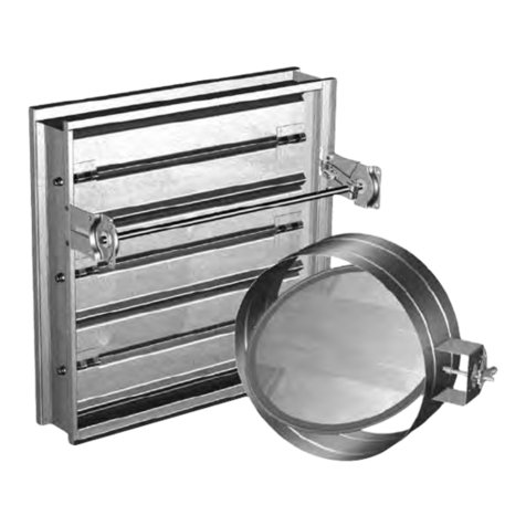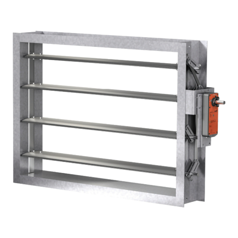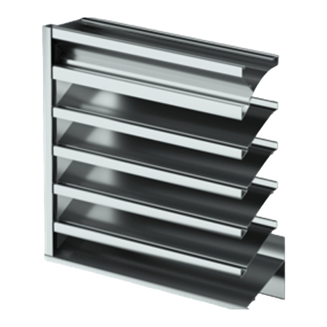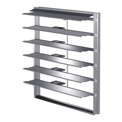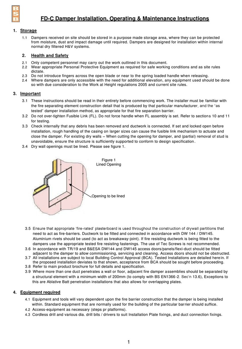
These instructions apply to 1½ hour rated fire dampers mounted in steel stud walls. Specific requirements in these
instructions are mandatory. These instructions meet the requirements of UL555. Installation shall comply with the
requirementsofNFPA90AStandardfortheInstallationofAirConditioningandVentilatingSystems.U.L.listings
R13317andR13743,CaliforniaStateFireMarshallistings3225-981:102and3225-1241:101,andNewYorkCityBSA/
MEAlisting260-91-Mastheyapplytothesedampers.
Installation for Steel Stud Connection (SSC) Option
6
1. NO ADDITIONAL SLEEVES OR ANGLES ARE
REQUIRED
The fire damper extended frame is an approved sleeve
and the Steel Stud Connection (SSC) Option allows
fastening of the fire damper sleeve directly to the
wall's steel stud framing. Damper frame shall extend
amaximumof6in.(152mm)beyondthewallopening
oneitherside.Maximumsizefiredamperthatmaybe
installedusingthisSSCoptionis36in.Wx36in.H
(914mmx914mm).
2. INSTALLATION
Fire damper with SSC option must be in place before
the wall is constructed or it can be installed as the wall
is being constructed. Wall opening is framed around
the fire damper before sheet rock or other wall board
material is applied to the steel studs. This installation
provides appropriate protection for duct penetrations
in fire resistant wall construction using steel studs with
a fire resistance rating less than 3 hours. The following
wall design numbers (as detailed in the UL Fire
Resistance Directory) are appropriate for fire damper
installations using this SSC option:
1HourDesign:U405,U406,U422,U434,U448,U451,
U456,U457,U465,U468,U469,U485,U494
1½HourDesign:U449,U452,U470,U471
2HourDesign:U403,U411,U412,U421,U425,U428,
U429,U443,U453,U474,U475,U477,U484,U491,
U495
3. FRAMING OF WALL OPENING
Formawallopening1/8in.(3mm)to1/4in.(6mm)
larger than the OD of the fire damper's extended frame
(sleeve) using the same metal studs and techniques
required by the wall design per the UL Fire Resistance
Directory. Open side of the steel stud channels shall
face the fire damper and encompass the damper's
retaining bar.
4. APPLY WALLBOARD AFTER DAMPER
INSTALLATION
Afterdamperisinstalled,wallboardshallbeapplied
to steel stud framework in the manner required by
the wall design per the UL Fire Resistance Directory
listing.Aroundthedamperperimeteruseaminimum
of 2 connections per side, spaced 12 in. (305mm)
maximum and located a maximum of 2 in. (51mm)
from each corner. No additional retaining angles are
required to complete the installation.
5. CONNECTING DUCTS TO THE FIRE DAMPER
AllductconnectionstoFD&DFD150Xseries
extended frame dampers must be “breakaway” type
connections.Allconnectionsshownonpage5&6are
considered breakaway. Factory furnished duct collars
ontypesR,CR,&COfiredampersarealsoconsidered
breakaway.
(TDC by Lockformer, TDF by Engle)
TDCandTDFsystemsareapprovedasbreakawayconnectionswheninstalledasdescribedintheSMACNADuct
ConstructionStandards.Standard6in.metalclipsmaybeusedwithspacing(seeFigure 8). Three-eighth in. metal
bolts and nuts may be used to fasten together corner pieces (see Figure 9).
Figure 8: Detail of proprietary flanged system breakaway
connections.
Figure 9: Detail of bolted corner.
$UCT
3LEEVE
IN
3TD#LIP
,ENGTH
#
,
$UCT
IN$UCT
2EQD
IN$UCT
2EQD
IN$UCT
2EQD
IN$UCT
2EQD
IN$UCT
3MALLER
2EQD
#LIP3PACING
4YPICAL4$#4$&JOINT
IN IN
IN
ININ
IN IN
ININ
Duct End
Flange
Corner Piece
3/8 in. bolt
(optional)
