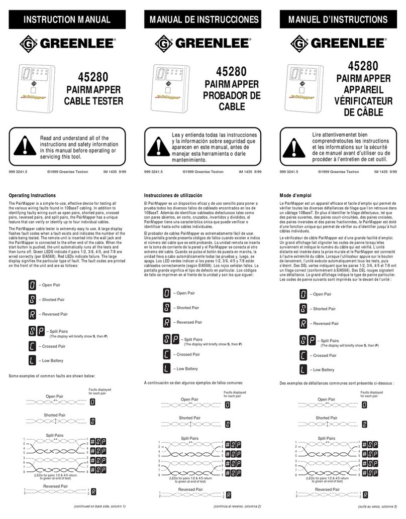
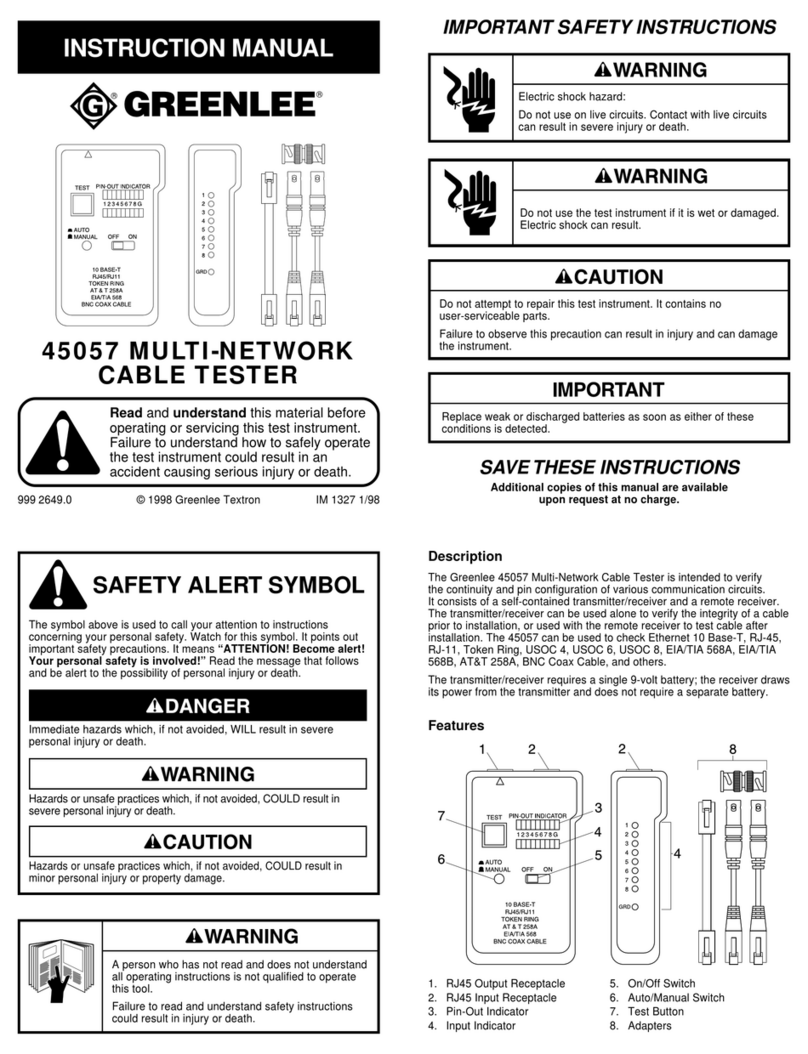
Greenlee 45053 User manual

999 2642.3 © 2000 Greenlee Textron IM 1325 REV 2 4/00
INSTRUCTION MANUAL
MANUAL DE INSTRUCCIONES
MANUEL D’INSTRUCTIONS
Read and understand all of the instructions and safety information in
this manual before operating or servicing this tool.
Lea y entienda todas las instrucciones y la información sobre seguridad
que aparecen en este manual, antes de manejar estas herramientas o
darles mantenimiento.
Lire attentivement et bien comprendre toutes les instructions et les
informations sur la sécurité de ce manuel avant d’utiliser ou de procéder
à l’entretien de cet outil.
45053
Universal Test Set
Aparato de prueba
universal
Ensemble de
vérification universel
45054
Universal Test Set Plus
Aparato Plus de prueba
universal
Ensemble de vérification
Plus universel
1 2 3
4 5 6
7 8 9
0
#

2
KEEP THIS MANUAL
Description
The 45053 and 45054 are test sets intended to troubleshoot communication circuits.
They include the following features:
• Three operating modes: Talk, Monitor, and On-Hook
• Tone or pulse dialing
• Mute function
• Automatic overcurrent detection and limitation
• Storage of up to 10 telephone numbers
• Two-tone ringer
• Sealed electronics
• Waterproof (IP65)
• Buoyant — floats if dropped in water
• Chemical resistant
Safety
Safety is essential in the use and maintenance of Greenlee tools and equipment. This
instruction manual and any markings on the tool provide information for avoiding hazards and
unsafe practices related to the use of this tool. Observe all of the safety information provided.
Purpose
This manual is intended to familiarize personnel with the safe operation and maintenance
procedures for the Greenlee 45053 Universal Test Set and 45054 Universal Test Set Plus.
Keep this manual available to all personnel.
Replacement manuals are available upon request at no charge.
Greenlee and are registered trademarks of Greenlee Textron.

45053 •45054
3
Important Safety Information
Read and understand all of the instructions and safety informa-
tion in this manual before operating or servicing this tool.
Failure to observe this warning can result in severe injury or
death.
This symbol is used to call your attention to hazards or unsafe practices which could
result in an injury or property damage. The signal word, defined below, indicates the
severity of the hazard. The message after the signal word provides information for
preventing or avoiding the hazard.
SAFETY ALERT SYMBOL
Immediate hazards which, if not avoided, WILL result in severe injury or death.
Hazards which, if not avoided, COULD result in severe injury or death.
Hazards or unsafe practices which, if not avoided, MAY result in injury or property
damage.

4
Important Safety Information
Replace weak or discharged batteries as soon as either of these conditions is detected.
Use this tool for the manufacturer’s intended purpose only. Use other than that which
is described in this manual can result in injury or property damage.
Do not perform any service or maintenance other than as instructed in this manual.
Failure to observe this precaution can result in injury or property damage.
Inspect the tester and cord for wear or damage. Replace worn, damaged or missing
components with Greenlee replacement parts. A damaged component may fail, resulting
in injury or property damage.
Electric shock hazard:
Contact with live circuits can result in severe injury or death.

45053 •45054
5
LED Indications
•Low Battery: Low Battery LED flashes red.
•Off-Hook Mode: Mode LED flashes red.
•Monitor Mode: Mode LED flashes green.
•On-Hook Mode: No LEDs are illuminated.
Hazard Indication
A constant ringing may indicate a hazard — excessive AC voltage on the line. If you hear this
alarm, remove the test set from the line carefully and immediately.
Identification
TALK
MONITOR
MUTE
1 2 3
4 5 6
7 8 9
0
#
LNR/PAUSE MEM STO POL
PULSE FLASH SPKR VOL
+–
ABC
JKL
TUV
GHI
PQRS
TONE
DEF
MNO
WZYZ
Polarity LED Mode LED
Low Battery

6
Operation
Note: The test set must have a charged battery installed in order to operate.
See Changing the Battery or Cord Set in this manual.
TALK
Press once to go off-hook (connect). Press again or press MONITOR to go on-hook
(disconnect).
To conserve battery life, the test set will shut off 90 seconds after removal from the line.
MONITOR
Press once to monitor the line without disturbing data, signal, or voice communication.
Press repeatedly to alternate between Monitor mode and off.
To conserve battery life, the test set will shut off after 20 minutes of monitoring or
90 seconds after removal from the line.
MUTE
Press and release to stop transmitting over the line or to eliminate sidetones.
Press again to talk.
Specifications
Monitor Impedance..........................................................................................> 400 kΩ@ 1 kHz
Loop Resistance (maximum)................................................................................................ 5 kΩ
Current Draw................................................................................................................... < 10 mA
DC Resistance
Talk Mode ................................................................................................................... < 300 Ω
Idle ........................................................................................... > 10 MΩ(30 µA @ 300 VDC)
Monitor .................................................................................... > 10 MΩ(30 µA @ 300 VDC)
Temperature
Operating .................................................................................. –34 to 60 °C (–29 to 140 °F)
Storage...................................................................................... –50 to 75 °C (–58 to 167 °F)
Battery......................................................................... 9 V alkaline (NEDA 1604A or IEC 6LR61)

45053 •45054
7
Dialing Features
PULSE
Pulse Dialing
With the test set connected to a communication line, press PULSE, then press TALK.
To mix pulse and tone dialing, select pulse as instructed above and dial the pulse digits. Then
press and dial the tone digits.
Notes:
• A called number with mixed digits will be stored in the Last Number Redial memory as
dialed.
• If the Last Number Redial function is used while in pulse mode, the number will be dialed
as a mix of pulse and tone digits. If used while in tone mode, all of the digits will be dialed
as tone digits.
The dialing mode automatically returns to tone-type dialing when the test set is removed from
the line or when the test set is switched off.
LNR/PAUSE
Last Number Redial / Pause
After going off-hook, press LNR/PAUSE (last number redial) to redial the last called number.
When programming, press LNR/PAUSE to insert a four-second pause in the dialing string.
STO
MEM
Store and Memory
The test set can store up to ten 24-digit telephone numbers, one under each of the
digits (0–9).
To store a telephone number:
1. While connected to a line and in the Talk mode, press STO.
2. Enter the telephone number.
3. Press MEM.
4. Press one of the digits (0–9).
In addition to digits, the memory will also store , , (flash) and (pause).
To recall a number, press MEM and then the storage location digit (0–9) while connected to a
line in the Talk mode.

8
Other Features
FLASH
Flash
Press FLASH to generate a timed line break.
SPKR
Speaker (45054 only)
The speaker allows One-Way Hands Free Operation (receive only).
• When in the Talk mode, press SPKR to use the speaker.
• When in the On-Hook mode, press SPKR to use the speaker. Press MONITOR to go on-
hook, or press TALK to go to the Talk mode.
VOL
Volume Control
To control the speaker volume, press VOL. The speaker is set to automatically start out at the
low setting. Press VOL to toggle between high and low volume.
Note: When using the high volume setting, the dial tone may fade. This does not indicate a
fault or a problem, and you may still dial out.
POL
Polarity
To determine the polarity, press POL. The LED will indicate polarity as follows:
• Red wire connected to ring (negative): Green LED
• Red wire connected to tip (positive): Red LED
Pressing POL while ringing will cause both LEDs to flash.
Use of the POL function will not disrupt data or speech.

45053 •45054
9
Changing the Battery or Cord Set
Note: Replace the battery in less than one minute to retain the contents of the memory.
1. Disconnect the unit from the circuit.
2. Press MONITOR to go to On-Hook mode.
3. Remove the three screws and the cover.
4. Replace the battery or cord set, as shown. Observe polarity.
5. Replace the cover and screws.
Note: Skipping Steps 1 and 2 might cause the unit to malfunction. If the test set does not
restart after changing the battery, disconnect the battery for two minutes. Then proceed with
Step 4.
–
+
Cleaning Instructions
Periodically wipe the case with a damp cloth and mild detergent.

10
Using the Test Set for Troubleshooting Circuits
Some general troubleshooting procedures and tips are provided here. These procedures may
require other tools or equipment that are specific to the communications system installation
trade. For a complete selection of DSV (data-signal-voice) tools, please refer to a Greenlee
full-line catalog, a Greenlee DSV catalog, or visit our website at www.greenlee.textron.com.
RFI (radio
frequency
interference)
Split pair An unbalanced pair near a radio transmitter will
be prone to RFI. Adding radio filters can reduce
the interference on the line (the symptom), but
does not solve the imbalance (the problem). To
troubleshoot, break the circuit down into
sections and check each section for split pairs
or a resistive imbalance.
Improperly removed bridge taps may also
introduce RFI. Bridge taps, which were once used
for party-line service (multiple users sharing a
cable pair), were often disconnected but left in
place, with a stub section of cable still connected.
This stub section can act as an antenna and
induce radio signals into the circuit.
Ground fault Check for the presence of AC line voltage. If AC
line voltage is present, measure the level. If it is
typical line voltage, contact the local electric
utility.
A long run of telephone
cable near a power line Contact the local electric utility.
Power hum Cable imbalance Break the circuit down into sections and check
each section for an imbalance.
Momentary or impulse
noise This may be due to an unbalanced cable, nearby
power switch gear, or similar equipment.
Popping, crackling The customer has an older carbon transmitter
type of telephone.
Noise Hiss (white noise);
pulse dialing causes a
momentary change in
the sound of the noise
This is probably due to water in the cables.
Cross connection Direct wiring fault Check for crossed pairs.
Cross-talk Split pair A split pair (a circuit made up of wires from two
separate wire pairs) will be unbalanced and
prone to cross-talk.
Constant ringing Telephone wire in
contact with an AC
power line
This is a potentially hazardous situation!
Remove the test set from the line carefully and
immediately.
Symptom* Possible Cause /
Troubleshooting Step Explanation
*Water may cause most of these symptoms and may cause multiple symptoms to appear at
the same time.

45053 •45054
11
Troubleshooting (cont’d)
Dead circuit Open circuit or short
circuit Break the circuit down into sections and check
each section for continuity.
(2b) When using the
test set in Monitor
mode, or with the
test set discon-
nected, the voltage
will be lower than
normal.
(2b) This indicates a partial short circuit.
(2a) When using the
test set in Monitor
mode, or with the
test set discon-
nected, the voltage
will be normal.
(2a) This indicates a high-resistance fault,
which restricts the amount of current
flowing through the circuit. Possible faults
include a poor connection, wet cables, or a
line extender failure.
Distortion, dialing
difficulty (1) When using the
test set in Talk
mode, the voltage
will be lower than
normal.
Intermittent or
variable current Wet cables or a bad
connection If accompanied by noise, the cause is usually
wet cables.
If no noise is present, the cause is probably a
bad connection in a cross-connect or a bad
connection at the central office.
Symptom* Possible Cause /
Troubleshooting Step Explanation
*Water may cause most of these symptoms and may cause multiple symptoms to appear at
the same time.

12
CONSERVE ESTE MANUAL
Descripción
Los modelos 45053 y 45054 son aparatos de prueba que han sido diseñados para reparar
averías en circuitos de comunicaciones.
Estos modelos incluyen las siguientes funciones y características:
• Tres modos de operación: Hablar, Monitorear y Colgar
• Marcación de tonos o de pulso
• Función de silenciador
• Detección de sobretensión y limitación automáticas
• Almacenamiento de hasta 10 números de teléfono
• Timbrador de dos tonos
• Equipo electrónico sellado
• Impermeable (IP65)
• Boyante — flota si cae al agua
• Resistente a sustancias químicas
Acerca de la seguridad
Es fundamental observar métodos seguros al utilizar y dar mantenimiento a las herramientas y
equipo Greenlee. Este manual de instrucciones y todas las marcas que ostenta la herramienta
le ofrecen la información necesaria para evitar riesgos y hábitos poco seguros relacionados
con su uso. Siga toda la información sobre seguridad que se proporciona.
Propósito de este manual
Este manual de instrucciones tiene como propósito familiarizar a todo el personal con los
procedimientos de operación y mantenimiento seguros para el Aparato de prueba universal,
modelo 45053, y para el Aparato Plus de prueba universal, modelo 45054, de Greenlee.
Manténgalo siempre al alcance de todo el personal.
Puede obtener copias adicionales de manera gratuita, previa solicitud.
Greenlee y son marcas registradas de Greenlee Textron.

45053 • 45054
13
Importante Información sobre Seguridad
Lea y entienda todas las instrucciones y la información sobre
seguridad que aparecen en este manual, antes de manejar esta
herramienta o darle mantenimiento.
De no observarse esta advertencia pueden sufrirse graves
lesiones o incluso la muerte.
Este símbolo se utiliza para indicar un riesgo o práctica poco segura que podría
ocasionar lesiones o daños materiales. Cada uno de los siguientes términos denota la
gravedad del riesgo. El mensaje que sigue a dichos términos le indica cómo puede
evitar o prevenir ese riesgo.
SÍMBOLO DE ALERTA
SOBRE SEGURIDAD
Peligros inmediatos que, de no evitarse, OCASIONARÁN graves lesiones o incluso la
muerte.
Peligros que, de no evitarse, PODRÍAN OCASIONAR graves lesiones o incluso la muerte.
Peligro o prácticas peligrosas que, de no evitarse, PUEDEN OCASIONAR lesiones o
daños materiales.

14
Importante Información sobre Seguridad
Si las pilas están bajas o se desgastan completamente, reemplácelas cuanto antes.
Utilice la herramienta únicamente para el propósito para el que ha sido diseñada por el
fabricante. Si se utiliza de una manera distinta a la descrita en este manual podrían
ocasionarse lesiones o daños materiales.
No realice ningún tipo de servicio o mantenimiento diferente al discutido en este
manual.
De no observarse estas precauciones pueden sufrirse graves lesiones o daños
materiales.
Inspeccione el verificador y el cable para comprobar que no están desgastados o
dañados. Reemplace los componentes desgastados, dañados o faltantes con piezas de
repuesto de Greenlee. Un componente averiado podría fallar y ocasionar lesiones o
daños materiales.
Peligro de electrocución:
El contacto con circuitos activados puede ocasionar graves
lesiones o incluso la muerte.

45053 • 45054
15
Identificación
TALK
MONITOR
MUTE
1 2 3
4 5 6
7 8 9
0#
LNR/PAUSE MEM STO POL
PULSE FLASH SPKR VOL
+–
ABC
JKL
TUV
GHI
PQRS
TONE
DEF
MNO
WZYZ
Diodo emisor de luz
(LED) de Modo
Diodo emisor de luz
(LED) de polaridad
Pila baja
Indicaciones de Diodos emisores de luz (LED)
•Pila baja: Diodo emisor de luz (LED) rojo de Pila baja parpadea.
•Modo Descolgar: Diodo emisor de luz (LED) rojo de Modo parpadea.
•Modo Monitorear: Diodo emisor de luz (LED) verde de Modo parpadea.
•Modo Colgar: No se ilumina ningún diodo emisor de luz (LED)
Indicación de riesgos
Un timbrado constante puede ser indicación de un riesgo —tensión CA excesiva en la línea.
Si usted escucha esta alarma, retire el aparato de prueba de la línea de inmediato
cuidadosamente.

16
Operación
Aviso: Para poder funcionar, el aparato de prueba debe tener instalada una pila cargada.
Consulte Reemplazo de la pila o del juego de cables en este manual.
TALK
(HABLAR)
Oprima una vez para descolgar (conectar). Oprima nuevamente u oprima MONITOR para
colgar (desconectar).
Para conservar la vida útil de la pila, apague el aparato de prueba 90 segundos luego de
haberlo retirado de la línea.
MONITOR (MONITOREAR)
Oprima una vez para monitorear la línea sin interrumpir las comunicaciones de datos, de
señales o de voz. Oprima repetidamente para alternar entre el modo Monitorear y apagado.
Para conservar la vida útil de la pila, apague el aparato de prueba luego de 20 minutos de
monitoreo o 90 segundos luego de haberse retirado de la línea.
MUTE (SILENCIADOR)
Oprima y suelte para interrumpir la transmisión a través de la línea o para eliminar tonos
laterales. Oprima nuevamente para hablar.
Especificaciones
Impedancia del monitoreo ................................................................................ > 400 kΩa 1 kHz
Resistencia de bucle (máxima)............................................................................................. 5 kΩ
Toma de corriente ........................................................................................................... < 10 mA
Resistencia CC
Modo Hablar .............................................................................................................. < 300 Ω
Desocupado ............................................................................. > 10 MΩ(30 µA @ 300V CC)
Monitor .................................................................................... > 10 MΩ(30 µA @ 300V CC)
Temperatura
Operación ....................................................................................... –34 a 60°C (–29 a 140°F)
Almacenamiento ............................................................................ –50 a 75°C (–58 a 167°F)
Pila ................................................................................. 9V alcalina (NEDA 1604A o IEC 6LR61)

45053 •45054
17
Funciones de marcación
PULSE
Marcación de pulso
A la vez que mantiene el aparato de prueba conectado a la línea de comunicación, oprima
PULSE y luego oprima TALK.
A fin de combinar la marcación de tonos y de pulso, seleccione pulso según se indicara
anteriormente y marque los dígitos de pulso. Luego oprima y marque los dígitos de tonos.
Notas:
•Un número llamado mediante dígitos combinados seráalmacenado en la memoria de
Repetición del último número marcado, según fue marcado.
•Si la función Repetición del último número marcado se utiliza mientras se encuentra en el
modo de pulso, el número serámarcado como una combinación de dígitos de pulso y de
tonos. Si se utiliza mientras se encuentra en el modo de tonos, todos los dígitos serán
marcados como dígitos de tonos.
El modo de marcación regresa automáticamente al tipo de marcación de tonos cuando el
aparato de prueba es retirado de la línea o apagado.
LNR/PAUSE
Repetición del último número marcado/Pausa
Luego de descolgar, oprima LNR/PAUSE (repetición del último número marcado) para discar
el número marcado más recientemente.
Cuando vaya a programar, oprima LNR/PAUSE para introducir una pausa de cuatro segundos
en la hilera de marcación.
STO
MEM
Almacenamiento y Memoria
El aparato de prueba puede almacenar hasta 10 números de teléfono de 24 dígitos, uno bajo
cada uno de los dígitos (0-9).
Para almacenar un número de teléfono:
1. Mientras se encuentra conectado a una línea y en el modo Hablar, oprima STO.
2. Marque el número de teléfono.
3. Oprima MEM.
4. Oprima uno de los dígitos (0-9).
Además de los dígitos, la memoria también almacenará, , (parpadeo) y (pausa).
Para volver a llamar un número, oprima MEM y luego el dígito (0-9) de localización de
almacenamiento mientras se encuentre conectado a una línea en el modo Hablar.

18
Otras funciones y características
FLASH
Parpadeo
Oprima FLASH (Parpadeo) para generar una interrupción de línea temporizada.
SPKR
Altavoz (únicamente el modelo 45054)
El altavoz permite una Operación de Manos Libres de Una Vía (solamente para recibir).
•Cuando se encuentre en el modo Hablar, oprima SPKR para utilizar el altavoz.
•Cuando se encuentre en el modo Colgar, oprima SPKR para utilizar el altavoz. Oprima
MONITOR para descolgar u oprima TALK para pasar al modo Hablar.
VOL
Control de volumen
Para controlar el volumen del altavoz, oprima VOL. El altavoz ha sido configurado para
comenzar en el ajuste bajo. Oprima VOL para alternar entre el volumen alto y el volumen bajo.
Aviso: Cuando utilice el ajuste de volumen alto, el tono de marcación podría desvanecerse.
Esto no es señal de fallo o de problemas, y usted podráseguir marcando.
POL
Polaridad
Para determinar la polaridad, oprima POL. Los LED indicarán la polaridad de la siguiente
manera:
•Cable rojo conectado al timbre (negativo): Diodo emisor de luz (LED) verde
•Cable rojo conectado a la punta (positivo): Diodo emisor de luz (LED) rojo
Si oprime POL mientras la unidad timbra, ambos diodos emisores de luz (LED) parpadearán.
Si utiliza la función POL, no se interrumpirán los datos o la voz.

45053 •45054
19
Reemplazo de la pila o del juego de cables
Aviso: Reemplace la pila antes de que transcurra un minuto para preservar el contenido de la
memoria.
1. Desconecte la unidad del circuito.
2. Oprima MONITOR para pasar al modo Colgar.
3. Retire los tres tornillos y la cubierta.
4. Reemplace la pila o el juego de cables según se muestra. Fíjese en la polaridad.
5. Vuelva a colocar la cubierta y los tornillos.
Aviso: Si omite los Pasos 1 y 2, podría ocasionar el funcionamiento errático de la unidad. Si el
aparato de prueba no reenciende, desconecte la pila por espacio de dos minutos. Luego
prosiga con el Paso 4.
–
+
Instrucciones de limpieza
Limpie periódicamente la caja utilizando un paño húmedo y detergente suave.

20
Fallo a tierra Verifique la presencia de tensión de línea de CA.
Si se encuentra tensión de línea de CA, mida el
nivel. Si es una tensión de línea común,
comuníquese con la compañía eléctrica local.
Timbrado
constante Cable del teléfono en
contacto con línea de
energía CA
¡Esta es una situación potencialmente
peligrosa! Retire el aparato de prueba de la
línea de inmediato cuidadosamente.
Cómo utilizar el aparato de prueba para reparar
averías en circuitos
A continuación se ofrecen algunos procedimientos y consejos generales sobre la resolución de
fallos. A fin de llevar a cabos estos procedimientos podrían necesitarse otras herramientas o
equipo especiales para la instalación de sistemas de comunicaciones. Para una selección completa
de herramientas DSV (datos-señal-voz), consulte el catálogo de línea completa de Greenlee, el
catálogo DSV de Greenlee o visite nuestra página electrónica en www.greenlee.textron.com.
Tendido largo de cable
de teléfono cerca de
líneas de energía
Comuníquese con su compañía eléctrica local.
Zumbido de la
potencia Desequilibrio de cables Divida el circuito en secciones y revise cada
sección para verificar la presencia de
desequilibrio.
Ruido momentáneo o
de impulso Esto puede deberse a un cable no balanceado,
mecanismo de interrupción de potencia cerca
de la unidad o equipo similar.
Disparos, crepitación El cliente posee un modelo antiguo de teléfono
tipo transmisor de carbón.
Ruido Silbido (ruido blanco);
la marcación de pulso
ocasiona un cambio
momentáneo en el
sonido del ruido
Esto se debe probablemente a la presencia de
agua en los cables.
Interconexión Fallo directo del
cableado Verifique la presencia de pares cruzados.
Diafonía Par dividido Un par divido (circuito compuesto de cables de
dos pares de cables distintos) no estará
balanceado y serápropenso a la diafonía.
Síntoma* Causa posible/
Resolución de fallos Explicación
*El agua puede ocasionar la mayor parte de estos síntomas y además causar que múltiples
síntomas aparezcan a la misma vez.
This manual suits for next models
1
Table of contents
Languages:
Other Greenlee Cable Tester manuals

Greenlee
Greenlee 38583 User manual

Greenlee
Greenlee 2012 User manual

Greenlee
Greenlee NETcat NC-500 User manual

Greenlee
Greenlee 2011 Manual

Greenlee
Greenlee 46053 User manual

Greenlee
Greenlee 45395 User manual

Greenlee
Greenlee 46054 User manual

Greenlee
Greenlee 45280 User manual

Greenlee
Greenlee 45057 User manual

Greenlee
Greenlee NETcat NC-100 User manual