Greenlee 2012 User manual

999 3290.3 © 2000 Greenlee Textron IM 1428 REV 1 3/00
2012
CIRCUIT TRACER
RASTREADOR
DE CIRCUITOS
DETECTEUR DE CIRCUIT
INSTRUCTION MANUAL
MANUAL DE INSTRUCCIONES
MANUEL D’INSTRUCTIONS
Read and understand all of the instructions and safety
information in this manual before operating or servicing this tool.
Lea y entienda todas las instrucciones y la información sobre
seguridad que aparecen en este manual, antes de manejar estas
herramientas o darles mantenimiento.
Lire attentivement et bien comprendre toutes les instructions et
les informations sur la sécurité de ce manuel avant d’utiliser ou de
procéder à l’entretien de cet outil.

2
Description
The Greenlee 2012 Circuit Tracer is intended to trace energized wires
and circuits. It can trace a circuit behind walls and under floors, and
locate the circuit breaker.
Safety
Safety is essential in the use and maintenance of Greenlee tools and
equipment. This instruction manual and any markings on the tool
provide information for avoiding hazards and unsafe practices related to
the use of this tool. Observe all of the safety information provided.
Purpose
This instruction manual is intended to familiarize all personnel with the
safe operation and maintenance procedures for the Greenlee 2012
Circuit Tracer.
Keep this manual available to all personnel.
Replacement manuals are available upon request at no charge.
and are registered trademarks of
Greenlee Textron.
KEEP THIS MANUAL
2012
3
Important Safety Information
This symbol is used to call your attention to hazards or unsafe
practices which could result in an injury or property damage.
The signal word, defined below, indicates the severity of the
hazard. The message after the signal word provides information
for preventing or avoiding the hazard.
SAFETY ALERT SYMBOL
Immediate hazards which, if not avoided, WILL result in severe
injury or death.
Hazards which, if not avoided, COULD result in severe injury or
death.
Hazards or unsafe practices which, if not avoided, MAY result in
injury or property damage.

4
Important Safety Information
Read and understand this material before
operating or servicing this equipment. Failure
to understand how to safely operate this tool
can result in an accident causing serious
injury or death.
Electric shock hazard:
Contact with live circuits can result in severe
injury or death.
Electric shock hazard:
Do not use the unit if it is wet or damaged.
Failure to observe this warning can result in severe injury or death.
2012
5
Important Safety Information
Do not operate with the case open.
Failure to observe this warning can result in severe injury or death.
Using this unit near equipment that generates electromagnetic
interference can result in unstable or inaccurate readings.
• Do not attempt to repair this unit. It contains no user-serviceable
parts.
• Do not expose the unit to extremes in temperature or high
humidity. See Specifications.
Failure to observe these precautions can result in injury and can
damage the unit.
6
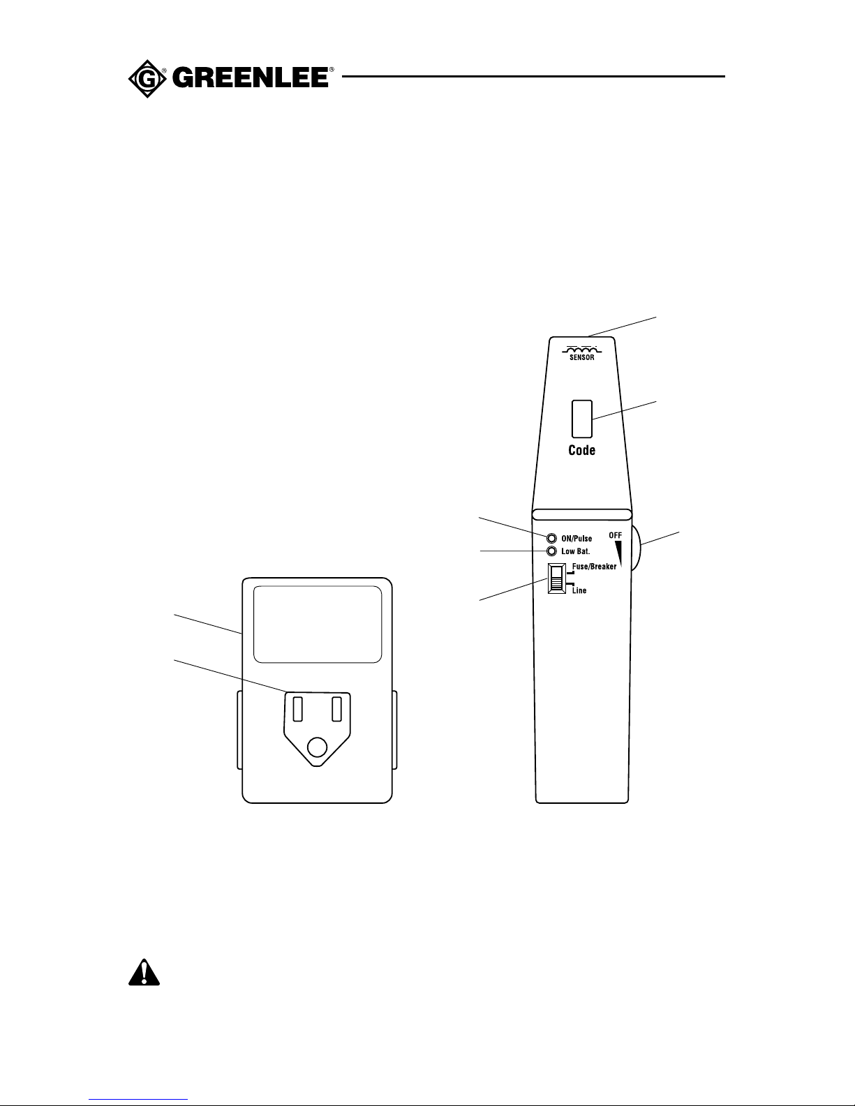
Identification
Receiver (2012-R)
1. Sensor
2. Code LED Display
3. OFF/Sensitivity Adjustment Knob
4. ON/Pulse LED
5. Low Battery LED
6. Selector
Transmitter (2012-T)
7. Main Unit
8. Plug (NEMA 5-15P)
Symbols on the Unit
Read the instruction manual.
1
2
3
4
5
6
7
8

2012
7
Introduction
The Greenlee 2012 Circuit Tracer consists of a transmitter and a
receiver. When plugged into an energized circuit, the transmitter will
generate a signal. This signal will be present along the entire circuit and
in any cords, tools or appliances connected to that circuit. The receiver
is then used to trace the circuit or locate the circuit breaker.
Operation
The receiver is more effective when it is held perpendicular to the
conductor it is tracing. See Typical Applications for illustrations of
typical uses.
Setup
1. Plug the transmitter into the circuit’s receptacle. (Receptable should
be NEMA 5-15R with 100 to 125 VAC, 50 to 60 Hz.)
2. Set the selector to “Line.”
3. Turn on the receiver by rotating the OFF/adjustment knob clockwise
until it clicks. The ON/Pulse LED will illuminate and a tone will
sound.
Note: If the ON/Pulse LED fails to illuminate, change the battery.
4. Rotate the knob counterclockwise until it meets resistance. This will
ensure that the test is started in the highest sensitivity.
5. Hold the receiver close to the transmitter. The ON/Pulse LED will
flash and an “H”will appear on the display.
•A series of tones will begin.
•As the receiver moves closer to the transmitter, the tone will
become higher pitched.
•If the tone sounds like a continuous hiss or buzz and the “H”is
not showing continuously, the transmitter does not have power.

8
6. Test the unit on a known functioning circuit or component.
(Receptable should be NEMA 5-15R with 100 to 125 VAC,
50 to 60 Hz.)
•If the unit does not function as expected on a known functioning
circuit, replace the battery in the receiver (2012-R).
•If the unit still does not function as expected, send the unit to
Greenlee for repair.
Tracing a Circuit
1. Set up the transmitter and receiver as described in Setup above.
2. Beginning at the transmitter, move the receiver in a sweeping
motion along the wall, floor or ceiling.
3. Using the tone and “H”display as a guide, trace the wiring. Adjust
the sensitivity according to the material of the wall, floor or ceiling.
•Decrease the signal’s intensity (and the receiver’s tone) by
turning the knob clockwise.
•Increase the signal’s intensity (and the receiver’s tone) by
turning the knob counterclockwise.
Note: If the signal becomes lost during this procedure, continue on to
where the circuit is likely to end (a junction box or fuse panel) and trace
back to the transmitter.
Locating a Circuit Breaker
1. Set up the transmitter and receiver as described in Setup above.
2. Slowly move the receiver toward the circuit breaker panel.
The ON/Pulse LED will blink and an “H”will appear on the display.
A series of tones will begin. The “H”will help distinguish the real
signal from interference or line noise.
Operation (cont’d)

2012
9
3. Back away from the panel and try again if the tone is a continuous
hiss or buzz.
4. Go to the next circuit breaker panel if no signal is emitted.
5. After locating the proper panel, open the panel door and set the
selector on the receiver to Fuse/Breaker.
6. Turn the knob clockwise until it meets resistance. This will ensure
that the test is started on the highest sensitivity.
7. Start at the top of the panel and scan each breaker, taking note of
which breakers give a signal.
8. Decrease the signal’s intensity (and the receiver’s tone) by turning
the knob counterclockwise.
9. Scan the breakers that previously gave a signal.
10. Repeat steps 7 through 9 until only one breaker gives a signal. The
transmitter is connected to the circuit powered by this circuit
breaker.
Note: If there is any doubt as to which is the correct breaker or fuse
(due to unusual breaker design, wiring or the possibility that two
breakers are feeding the same circuit), have the wiring checked by a
qualified electrician.
Operation (cont’d)

10
Typical Applications
Finding Breaker Panel Identifying Circuit Breakers
Tracing Wires
in Walls
Table of contents
Languages:
Other Greenlee Cable Tester manuals

Greenlee
Greenlee 38583 User manual

Greenlee
Greenlee 2011 Manual

Greenlee
Greenlee NETcat NC-500 User manual

Greenlee
Greenlee 46054 User manual

Greenlee
Greenlee 45053 User manual

Greenlee
Greenlee 45280 User manual

Greenlee
Greenlee 45395 User manual

Greenlee
Greenlee 45057 User manual

Greenlee
Greenlee NETcat NC-100 User manual

Greenlee
Greenlee 46053 User manual


