manuals.online logo
Brands
  1. Home
  2. •
  3. Brands
  4. •
  5. Greenlee
  6. •
  7. Cable Tester
  8. •
  9. Greenlee 45057 User manual

Greenlee 45057 User manual

INSTRUCTION MANUAL
999 2649.0 © 1998 Greenlee Textron IM 1327 1/98
Hazards or unsafe practices which, if not avoided, COULD result in
minor personal injury or property damage.
Hazards or unsafe practices which, if not avoided, COULD result in
severe personal injury or death.
Immediate hazards which, if not avoided, WILL result in severe
personal injury or death.
The symbol above is used to call your attention to instructions
concerning your personal safety. Watch for this symbol. It points out
important safety precautions. It means “ATTENTION! Become alert!
Your personal safety is involved!” Read the message that follows
and be alert to the possibility of personal injury or death.
SAFETY ALERT SYMBOL
A person who has not read and does not understand
all operating instructions is not qualified to operate
this tool.
Failure to read and understand safety instructions
could result in injury or death.
Do not attempt to repair this test instrument. It contains no
user-serviceable parts.
Failure to observe this precaution can result in injury and can damage
the instrument.
Electric shock hazard:
Do not use on live circuits. Contact with live circuits
can result in severe injury or death.
Do not use the test instrument if it is wet or damaged.
Electric shock can result.
Replace weak or discharged batteries as soon as either of these
conditions is detected.
IMPORTANT SAFETY INSTRUCTIONS
SAVETHESE INSTRUCTIONS
Additional copies of this manual are available
upon request at no charge.
Description
The Greenlee 45057 Multi-Network Cable Tester is intended to verify
the continuity and pin configuration of various communication circuits.
It consists of a self-contained transmitter/receiver and a remote receiver.
The transmitter/receiver can be used alone to verify the integrity of a cable
prior to installation, or used with the remote receiver to test cable after
installation. The 45057 can be used to check Ethernet 10 Base-T, RJ-45,
RJ-11, Token Ring, USOC 4, USOC 6, USOC 8, EIA/TIA 568A, EIA/TIA
568B, AT&T 258A, BNC Coax Cable, and others.
The transmitter/receiver requires a single 9-volt battery; the receiver draws
its power from the transmitter and does not require a separate battery.
Read and understand this material before
operating or servicing this test instrument.
Failure to understand how to safely operate
the test instrument could result in an
accident causing serious injury or death.
45057 MULTI-NETWORK
CABLE TESTER
5. On/Off Switch
6. Auto/Manual Switch
7. Test Button
8. Adapters
1. RJ45 Output Receptacle
2. RJ45 Input Receptacle
3. Pin-Out Indicator
4. Input Indicator
Features
Greenlee Textron / Subsidiary of Textron Inc.
4455 Boeing Drive, Rockford, IL 61109-2988 USA
Customer Service (International): 815/397-7070 • Fax: 815/397-1391
Customer Service (North America): 800/435-0786
Fax: 800/451-2632, 815/397-1865
Canada Fax: 800/524-2853 Printed in the U.S.A.
PR4
PR3
8-position
Token Ring BNC Plug
PR1
USOC 4 (Prs. 1 & 2)
USOC 6 (Prs. 1, 2 & 3)
PR2 PR3
PR1 PR2
Ethernet
10Base-T
PR4
USOC 8
PR1
PR2
PR3
PR1
PR3
EIA/TIA -
568A
PR2PR4 PR1
PR3PR4
PR2
EIA/TIA-568B
AT & T258A
Short Circuit across Pin 2 and Pin 3
Multiple Pin-Out Indicator and Input Indicator LED’s flash simultaneously.
Short Circuit Indication
Input Indicator LED does not flash in response to the corresponding
Pin-Out Indicator LED.
Open at Pin 6
Open Circuit Indication
Pin 3 and Pin 5 are Reversed
Miswire
Failure Results for Any Test:
Input Indicator LED flashes, but does not correspond to the correct
Pin-Out Indicator LED.
Operation
Loopback Test
1. Refer to the illustration labeled Loopback Test. Connect the cable to
the RJ45 output receptacle (labeled ▲) and the RJ45 input receptacle.
2. Turn the power ON. The Pin-Out Indicator LED’s will begin to flash in
sequence. The Input Indicator LED’s will flash in response.
Note: To test the cable manually, switch the Auto/Manual Switch to
Manual. Press the Test Button repeatedly until each conductor
has been tested.
Lifetime Limited Warranty
Greenlee warrants to the original purchaser of these goods for use that
these products will be free from defects in workmanship and material for
their useful life, excepting normal wear and abuse. This warranty is
subject to the same terms and conditions contained in Greenlee’s
standard one year limited warranty.
For all Test Instrument repairs, ship units Freight Prepaid to:
Greenlee Textron at
4411 Boeing Drive, Rockford, IL 61109-2932 USA.
Mark all packages: Attention TEST INSTRUMENT REPAIR. For items not
covered under warranty (such as dropped, abused, etc.), repair cost quote
available upon request.
Note: Prior to returning any test instrument, please check replaceable
batteries or make sure the battery is at full charge.
Remote Test
Remote Test
Electric shock hazard:
Do not use on live circuits. Contact with live circuits
can result in severe injury or death.
1. Refer to the illustration labeled Remote Test. Connect one end of the
cable to the RJ45 output receptacle (labeled ▲) of the transmitter/
receiver. Connect the other end of the cable to the RJ45 input jack of
another transmitter/receiver or the remote receiver. Use the adapters
if necessary.
2. Turn the power ON. The Pin-Out indicator LED’s will begin to flash in
sequence. The Input Indicators LED’s will flash in response.
Loopback Test
Normal Results:
Continuity at Shield
Continuity at Pin 1
Coaxial Cable
Continuity at Each Conductor
LED 1 - Center conductor. LED 2 - Shield

Other Greenlee Cable Tester manuals

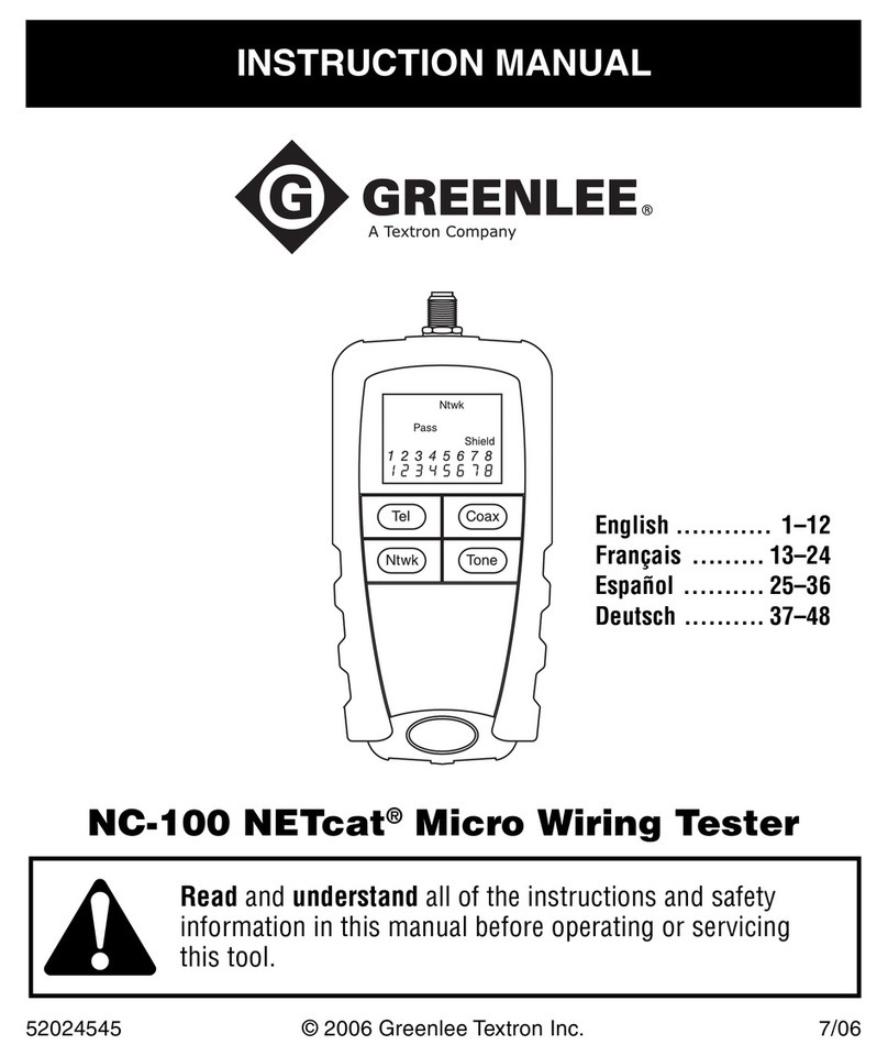
Greenlee NETcat NC-100 User manual

Greenlee

Greenlee NETcat NC-100 User manual

Greenlee PA1594 User manual

Greenlee

Greenlee PA1594 User manual

Greenlee 46053 User manual

Greenlee

Greenlee 46053 User manual

Greenlee 45053 User manual

Greenlee

Greenlee 45053 User manual

Greenlee 38583 User manual

Greenlee

Greenlee 38583 User manual

Greenlee 46054 User manual

Greenlee

Greenlee 46054 User manual

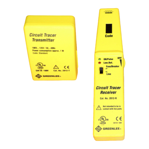
Greenlee 2012 User manual

Greenlee

Greenlee 2012 User manual

Greenlee 45280 User manual

Greenlee

Greenlee 45280 User manual

Greenlee NETcat NC-500 User manual

Greenlee

Greenlee NETcat NC-500 User manual

Greenlee 5123 User manual

Greenlee

Greenlee 5123 User manual

Greenlee 45395 User manual

Greenlee

Greenlee 45395 User manual

Greenlee 2011 Manual

Greenlee

Greenlee 2011 Manual

Popular Cable Tester manuals by other brands

Triplett TDR100 user manual

Triplett

Triplett TDR100 user manual

Softing CableMaster 200 quick start guide

Softing

Softing CableMaster 200 quick start guide

Supereyes NS-468 instruction manual

Supereyes

Supereyes NS-468 instruction manual

Platinum Tools VDV MapMaster 3.0 T130 user manual

Platinum Tools

Platinum Tools VDV MapMaster 3.0 T130 user manual

Fluke MicroScanner Series Getting started guide

Fluke

Fluke MicroScanner Series Getting started guide

ETT McCheck  ST-50 USB Reference manual

ETT

ETT McCheck ST-50 USB Reference manual

Sperry instruments Cable-Test TT64200 operating instructions

Sperry instruments

Sperry instruments Cable-Test TT64200 operating instructions

Velleman VTLAN6 user manual

Velleman

Velleman VTLAN6 user manual

RS PRO CT2690 instruction manual

RS PRO

RS PRO CT2690 instruction manual

Amprobe AT-5000 user manual

Amprobe

Amprobe AT-5000 user manual

Tripp Lite T040-001-HDMI owner's manual

Tripp Lite

Tripp Lite T040-001-HDMI owner's manual

Velleman VTTEST11N user manual

Velleman

Velleman VTTEST11N user manual

caberQU C2C v2.5k manual

caberQU

caberQU C2C v2.5k manual

TRENDnet TC-NT2 instruction manual

TRENDnet

TRENDnet TC-NT2 instruction manual

Krystufek PANCONTROL PAN Leckstromzange operating manual

Krystufek

Krystufek PANCONTROL PAN Leckstromzange operating manual

manuals.online logo
manuals.online logoBrands
  • About & Mission
  • Contact us
  • Privacy Policy
  • Terms and Conditions

Copyright 2025 Manuals.Online. All Rights Reserved.