Grifco GLMe2 User manual

- A300117

2
THESE ARE IMPORTANT SAFETY INSTRUCTIONS. FOLLOW ALL INSTRUCTIONS AS INCORRECT
INSTALLATION CAN LEAD TO SEVERE INJURY OR DEATH
An electrician must disconnect electric power to the commercial
door opener and control before making repairs or removing
covers.
Keep commercial door balanced.
Do not attempt to loosen, move or adjust
them.
Do not wear rings, watches or loose clothing
remove all
ropes connected to the commercial door
Connect the power supply cord only
to properly earthed mains if applicable.
labels
Disengage all existing commercial door locks
in a location where the commercial door is visible during
operation . Do not allow children to operate push button s) or
remote control s).
Activate opener only when the door is in full view, free of ob-
structions and opener is properly adjusted. No one should enter
or leave the building while the door is in motion.
After t e installation a final test of t e full function of t e sys-
tem and t e full function of t e safety devices must be done.Make sure t at people w o install, maintain or operate t e door
follow t ese instructions.
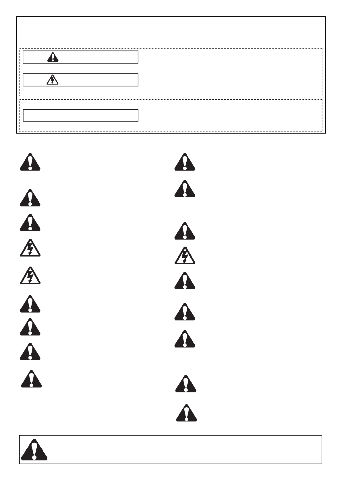
Safety Symbol and Signal Word review
WARNING
WARNING
CAUTION
Mec anical
Electrical
T e opener cannot be used wit a driven part incorporating a
wicket door
T e actuating member of a biased-off switc is to be located
wit in direct sig t of t e door
Unless it is key operated
not accessible to t e public
If t e opener is installed at a eig t less t an 2.5 metres from
floor level or any ot er level from w ic t e unit can be ac-
cessed (eg mezzanine) t e installer is responsible to fit guards to
t e opener to prevent access to t e c ain drive.
WARNING:
Important safety instructions. It is important for the
safety of persons to follow all instructions. SA E these instructions.
Use t e commercial door control for its intended purpose.

3
TABLE OF CONTENTS
Safety instructions 2
Introduction 4
Planning 4
Mounting 5
Connection 6-8
•
•
•
Control Interface Overview
Setup and Adjustment 10-11
•
•
•
Installing Entrapment Protection Devices 12
Wired Access Control / Toggle Input 12
Installation Expansion 13
Typical Car Park Application (example) 13
Main Control Board (MCB) layout 14
Accessories / Expansion 15-16
•
•
•
•
•
•
•
•
•
Auto Close & Wireless Accessory set up 17-18
•
Maintenance 19
•
Troubles ooting 20-21
•
Notes 22-23
•
Warranty 24

4
WARNING
INTRODUCTION
CAUTION
PLANNING

5
MOUNTING

6
Examples of compatible models: ML053M, ML103M,
MH103M & ML153M
Example of compatible model: ML051M
Example of compatible models: ML102M &
MH102M
ELECTRICAL CONNECTION
GLMe2 must
•
•
•
•
wit out
neutral
Examples of compatible models: ML053M,
ML103M, MH103M & ML153M
A WITH
C D
SUPPLY CONNECTION

7
Example of compatible Grifco model: ML051M
MOTOR CONNECTION
FOR THREE PHASE, DO NOT CONNECT ANY WIRE TO THE NEUTRAL TERMINAL!!
Examples of compatible Grifcomodels: ML053M, ML103M, MH103M & ML153M
Example of compatible Grifcomodels: ML102M & MH102M

8
LIMIT CONNECTION
Connection of t e primary wiring is now complete. Proceed to t e following pages for set up of t e
door operation before connecting any safety devices or access control systems.

9
GLMe2
OFF:
AUTO:
AUTO / MAN:
CONTROL INTERFACE
WARNING
Controller Key Switc

10
SETUP AND ADJUSTMENT
C ecking power
Door direction

11
Setting limits
WARNING: Limits are extremely sensitive; a small cam movement may correspond to a large amount of door travel.
SETUP AND ADJUSTMENT (cont)
WARNING
Entrapment Protection
WARNING
WARNING

12
Installing Entrapment Protection Devices
(may require terminal blocks P/N TBT2A-5)
must
Connection overview:
IR1:
IR2:
VDC OUT:
BUMP:
Note: W en installing Entrapment Protection Devices ensure t at t e door is at t e open limit position.
Note: All Entrapment Protection Devices need to be activated once after installation to be learned correctly. Normally closed
Entrapment Protection Devices and monitored Bump Edges require one simulated obstruction to be learned by t e opener.
Once learned, latc closing will be allowed w en set.
Erase Entrapment Protection Devices
Reactivate Entrapment Protection Devices
ENTRAPMENT PROTECTION DEVICE CONNECTION
WIRED ACCESS CONTROL / TOGGLE INPUT

13
INSTALLATION EXPANSION
Example of a Typical Car Park Application
Typical Car Park Configuration
•
•
•
•
Access Control Options
•
•
Transmitter Management
Exit Control
•
•
Note – T e Toggle Input will accept N/O inputs from multiple access control devices eg, bot a separate entry and exit control.
Auto Close Feature
Advanced Logic Functionality

14
MAIN CONTROL BOARD (MCB)
1 10
2 11
3 12
4 13
5 14
6 15
7
8
9
GLMe2.
Note: MCB layout may vary depending on build type
9 15
10
4
6
1 12
13
7
5
11
8
2
3
14

15
ACCESSORIES / EXPANSION
- Call 1800 GRIFCO for assistance wit any of t e above accessories, or ot er enquiries -
Model:
GPS15 - Reflective beam kit
GPS15RK – Above including 2 x E9 5G
transmitters
Send / Receive type also available:
GPS772 – Send/Receive beam kit
GPS772RK - Above including 2 x E9 5G
transmitters

16
ACCESSORIES / EXPANSION
P/N MinEB
1800 GRIFCO P/N EB1-G
Expansion Board: Model EB1-G
Mini Expansion Board: MinEB

17
UP
DOWN
STOP
SET
POWER ON
STATUS
LIMIT ERROR
LRN
RST
Lower Rig t corner of GLMe2 MCB
AUTO CLOSE & WIRELESS ACCESSORY SET UP
Action Button Sequence
SET AUTO TIMER TO CLOSE FROM
THE CONTROLLER
( wit no expansion board fitted)
• SETDOWN
green
• UP
• DOWN
• green
green
• SET
•
DOWN green
•
Controller Key Switc
Controller and MCB button reference

18
Action Button Sequence
LEARNING A NEW WIRELESS
ACCESSORY (e.g. a transmitter)
FROM THE CONTROLLER
• SETSTOP
green
• WIRELESS ACCESSORY BUTTON
orange
• STOP
LEARNING A NEW WIRELESS
ACCESSORY FROM THE MCB
• LRN
• WIRELESS ACCESSORY BUTTON
• LRN
ERASE ALL LEARNED WIRELESS
ACCESSORIES FROM THE
CONTROLLER
• SET
• STOP
•
LEARN THE E138G WIRELESS WALL
CONTROL FROM THE CONTROLLER
up/down
open/stop
up/down
Two C annel Wireless Wall Control
• SETSTOP
green
• WIRELESS ACCESSORY BUTTON
orange
•
• STOP
Dedicated Up/Down Wireless Wall Control (only for applications wit out entrapment protection)
• SETSTOP
green
• E138G TOP
LIMIT ERROR
• E138G LOWER
• STOP
• E138G LOWER
LEARN THE E840G WIRELESS
KEYPAD FROM THE CONTROLLER
• SET
• SET STOP
green
•
• ENTER
•
• STOP
• RADIO LOCK
NOTE:
•
•
NOTE:
AUTO CLOSE & WIRELESS ACCESSORY SET UP

19
MAINTENANCE
GLMe2
Mont ly
Quarterly
To view total cycles (limits must be set)
•
•
•
•
To read number of cycles, follow t e ‘Reading Status Flas es’ routine described below.
Reading Status Flas es
•
•
•
To reset error
4591014 15
•
•
HHDT (Hand eld Diagnostic Tool)
Power MUST be turned off before servicing or adjusting t e opener. Disconnect t e supply w en cleaning!

20
TROUBLESHOOTING
Status Indicator (Green) Flas / Problem Table
IMPORTANT NOTE
1800 GRIFCO customerservice@c amberlainanz.com in Australia or in New
Zealand call 0800 653 667.
No. flas es/
Problem
Meaning
Possible causes
Possible Solutions
This manual suits for next models
1
Table of contents
Other Grifco Door Opening System manuals