Griots Garage BATTERY MANAGER V User manual

BATTERY MANAGER V
AUTOMATICALLY MAINTAINS PEAK BATTERY CHARGE
FOR USE ON 6-VOLT & 12-VOLT BATTERIES
Have fun in your garage!®
FEATURES & SPECIFICATIONS
•
Reverse Polarity Protection
•
Safe, Multi-Phase Charging Process
•
Input: 120Vac ~60hz 1.0A 120W
•
Exercising Mode Maintains Battery Health
•
Output: 12Vdc 4.0A, 6Vdc 4.0A
•
Cable Clamps
•
Reconditions Dead & Weak Batteries
•
Hard-Wire Mount
•
Use With 6V Or 12V Batteries
•
Battery Manager IV Cable Adapter
•
Recovery Mode (Resumes Charging After Power Failure)
•
Cigarette Lighter Adapter
Read rear warning label
Battery Volts Selector
Battery Type Selector
Start/Stop Selector Reverse Polarity Indicator
Error Indicator
Recovery Mode Indicator
Power Indicator
Battery Voltage Indicators Battery Type Indicators
Charging Indicator Full Charge Indicator
ITEM 92232

Thank you for choosing this quality Griot's product. The Battery
Manager V features state-of-the-art technology to improve battery
performance, longevity, and overall condition. Please read and
understand all instructions before using the Battery Manager V.
Enjoy the best!
SAFETY PRECAUTIONS
WARNING: Read these instructions completely before using the
Battery Manager V and save them for future reference. Before
using the Battery Manager V to charge a battery, read these
instructions and the instruction manual/safety information provided
by the car, truck, boat or equipment manufacturer. Following all
manufacturers’ instructions and safety procedures will reduce the
risk of accident.
Working around lead-acid batteries may be dangerous. Lead-
acid batteries release explosive gases during normal operation,
charging and jump starting. Carefully read and follow these
instructions for safe use. Always follow the specific instructions in
this manual and on the Battery Manager V each time you use the
Battery Manager V. All lead-acid batteries (car, truck and boat)
produce hydrogen gas which may violently explode in the presence
of fire or sparks. Do not smoke, use matches or a cigarette lighter
while near batteries. Do not handle the battery while wearing vinyl
clothing because static electricity sparks are generated when vinyl
clothing is rubbed. Review all cautionary material on the Battery
Manager V and in the engine compartment.
Always wear eye protection, appropriate protective clothing and
other safety equipment when working near lead-acid batteries.
Do not touch eyes while working on or around lead-acid batteries.
If battery acid contacts skin or clothing, wash immediately with
soap and water. If acid enters eye, immediately flood eye with cold
running water for at least 10 minutes and get medical attention
immediately.
Always store clamps away from each other or common
conductors. Improper storage of clamps may cause the clamps to
come in contact with each other, or a common conductor, which
would be hazardous if the unit was plugged into an AC outlet.
Use extreme care while working within the engine compartment,
because moving parts may cause severe injury. Read and follow all
safety instructions published in the vehicle's Owner's Manual.
Batteries being charged with the Battery Manager V unit likely
contain liquid acids which are hazardous if spilled. Failure to follow
instructions may cause damage or explosion, always shield eyes.
Read entire instruction manual before use.
Warning: This product contains a chemical known to the State of
California to cause birth defects or other reproductive harm. Wash
hands after handling.
PREPARING TO CHARGE A BATTERY
1. I
f it is necessary to remove the battery from the vehicle to charge,
always remove the grounded terminal from the battery first. Make
sure all accessories in the vehicle are off, to avoid causing an arc.
2. Be sure the area around battery is well ventilated while battery
is being charged. Make sure there is no gasoline or other
combustible material in the vicinity.
3. Clean battery terminals with a mixture of baking soda and hot
water. Be careful to avoid corrosion coming in contact with eyes.
4. Add distilled water in each cell until battery acid reaches level
specified by battery manufacturer. This helps purge excessive
gas from cells. Do not overfill. For Maintenance-Free Batteries,
carefully follow the manufacturer's recharging instructions.
5. Study all battery manufacturer's specific precautions,
i.e. - removing/not removing cell caps while charging and
recommended rates of charge.
6. Determine voltage of battery by referring to vehicle owner's
manual and make sure that charger output voltage matches.
LOCATING THE CHARGER
1. Locate the charger as far away from the battery as the cables
permit.
2. Never place the charger directly above the battery being
charged; gases from the battery will corrode and damage the
charger.
3. Never allow battery acid to drip on the charger when reading
specific gravity or filling the battery.
4. Do not operate the charger in a closed area or restrict ventilation
in any way.
5. Do not set a battery on top of the charger.
6. Locate the charger at least 18" above the floor.
7. Do not place the charger where rain, snow or other moisture
could drip on it.
CONNECTING TO BATTERY INSTALLED IN A VEHICLE
Caution: A marine (boat) battery must be removed and charged
on shore. To charge it onboard requires equipment specially
designed for marine use.
Caution: A spark near the battery may cause battery explosion. To
reduce this risk:
1. Position AC and DC cords to reduce risk of damage by hood,
door or moving engine part.
2. Stay clear of fan blades, belts, pulleys and other parts that can
cause injury to persons.
3. Check polarity of battery posts. POSITIVE ( POS, P, + ) battery post
usually has larger diameter than NEGATIVE ( NEG, N, – ) post.
4. Determine which post of battery is grounded (connected) to
the chassis. If the negative post is grounded to the chassis (as in
most vehicles), see instruction 5a. If the positive post is grounded
to the chassis, see instruction 5b.
5. a) For NEGATIVE GROUNDED vehicle, connect POSITIVE
(Red) clip from the battery charger to the POSITIVE (POS, P, +)
ungrounded post of the battery.
b) For POSITIVE GROUNDED vehicle, connect the NEGATIVE
(Black) clip from the battery charger to the NEGATIVE (NEG, N, –)
ungrounded post of the battery. (This arrangement is usually found
in pre-1970 foreign vehicles or pre-1970 farm tractors. This is a rare
occurrence.)
6. Connect the remaining battery charger clip to the vehicle chassis
or engine block, as far away from the battery as possible. Do
not connect the clip to carburetor, fuel lines or sheet metal body
parts. Connect to a heavy gauge metal part of the frame or
engine block.
7. When disconnecting charger, turn charging sequence OFF by
depressing the "CHARGE" button, disconnect AC cord, remove
clip from vehicle chassis and remove clip from battery terminal.
8. Refer to the Operating Instructions for information on setting
selector switches.
CONNECTING TO BATTERY OUTSIDE OF A VEHICLE
1. Check polarity of battery posts. POSITIVE (POS, P, +) battery post
usually has a larger diameter than NEGATIVE (NEG, N, –) post.
2. Attach at least a 24" long, #6 gauge (AWG) insulated battery
cable (not included) to NEGATIVE (NEG, N, –) battery post.
3. Connect POSITIVE (RED) charger clip to POSITIVE (POS, P, +) post
of battery.

4. Position yourself and the free end of the cable (installed in step
#2) as FAR away from the battery as possible. FACING AWAY
FROM THE BATTERY, connect the NEGATIVE (Black) charger clip
to the free end of the cable.
5. When charging is complete, turn charging sequence off by
depressing the "CHARGE" button. Then disconnect charger,
always in reverse sequence of connecting procedure and break
first connection while as far away from battery as practical.
SELECTING THE BATTERY TYPE
For Conventional and Maintenance-Free flooded (wet) batteries, the
ideal Battery Type selection is "FLD." For batteries identified as AGM
construction, the ideal Battery Type selection is "AGM". For most
Spiral Wound batteries, the best Battery Type selection is "AGM".
For Deep Cycle & Marine batteries, determine whether it's a wet cell
or another type of of construction. This will determine the proper
Battery Type selection. For most Lithium starting batteries, the ideal
Battery Type selection is LiFe (LiFePO4 – Lithium Iron Phosphate).
Note: When charging lithium batteries, please note that there are
many different lithium battery chemistries. The Lithium charging
setting on this charger is specifically for Lithium Iron Phosphate
(LiFePO4) batteries and only these lithium batteries. The charger
should never be used for charging any other lithium battery type.
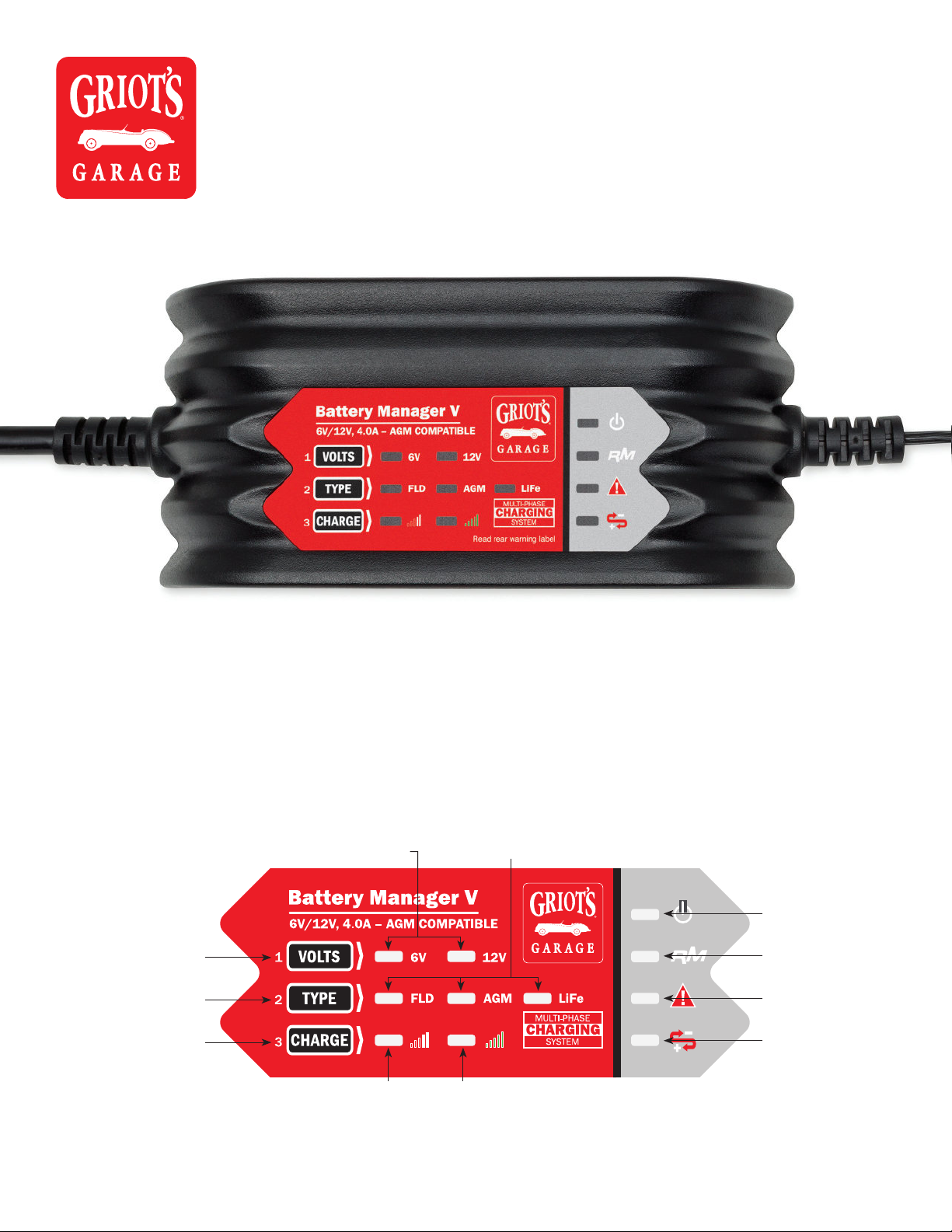
OPERATING INSTRUCTIONS
Upon making a proper battery connection, plug AC power cord
into an AC receptacle. All unit LEDs will light momentarily, then
only the LEDs corresponding to charging settings should stay lit.
The charger is now in Standby Mode. If an ERROR Indicator LED
illuminates, disconnect from AC power supply immediately and
determine the cause of the alarm. The POLARITY light indicates
reverse polarity error connection, while the ERROR light indicates
the detection of a battery fault, such as a shorted connection. To
charge a battery:
1. Choose a battery voltage charge setting. The default setting is
the 12V mode, which will apply to most charging applications. To
charge in 6V mode, push the voltage setting button until the "6V"
LED is lit.
2. Choose a battery type. Refer to "Selecting The Battery Type"
above.
3. Press the "CHARGE" button and the charging indicator LED
will illuminate. The charger will automatically commence and
complete the charging process. If you press the "CHARGE" button
at any point during the charging sequence, the charger will stop
charging and return to Standby Mode. Note 1: If the ERROR LED
illuminates, disconnect from AC power immediately and determine
the cause of the alarm. See Battery Manager V Features for a list
of conditions that might cause this warning. Note 2: The charger
is designed to protect against faults and shorts (see Battery
Manager V Features). If the battery to be charged has an open
circuit voltage of less than 1V, the charger will indicate a fault. If,
after unplugging unit, checking connections and verifying all
settings, you determine the problem causing the "fault" condition
is battery voltage below 1V, you can override the charger's
protection by holding down the "CHARGE" button for 3 seconds.
The charger will commence the charging sequence and, assuming
there are no other hindrances that caused the fault indication, will
complete the charging process and automatically turn off when
the battery has reached full charge.
4. When the battery approaches full charge and enters the
Completion Phase, the green FULL CHARGE indicator will light
and the CHARGING LED indicator will flash. At this point, if time
is critical, the battery can be put into service if it will be used
in a charging situation, such as in a vehicle that will be used
immediately. To reach a true 100% state of charge, the charger
should stay connected until the charger reaches the Rest Phase,
when only the green CHARGING COMPLETE is
slowly flashing.
5. When you are finished with the charging process, disconnect
AC power cord from AC outlet, then disconnect DC leads from
vehicle ground (if charging with battery in vehicle) and battery in
the reverse sequence of the connection procedure.
6. In the event of a power outage, your Battery Manager V is
equipped with a RECOVERY MODE feature. See back page for
details.
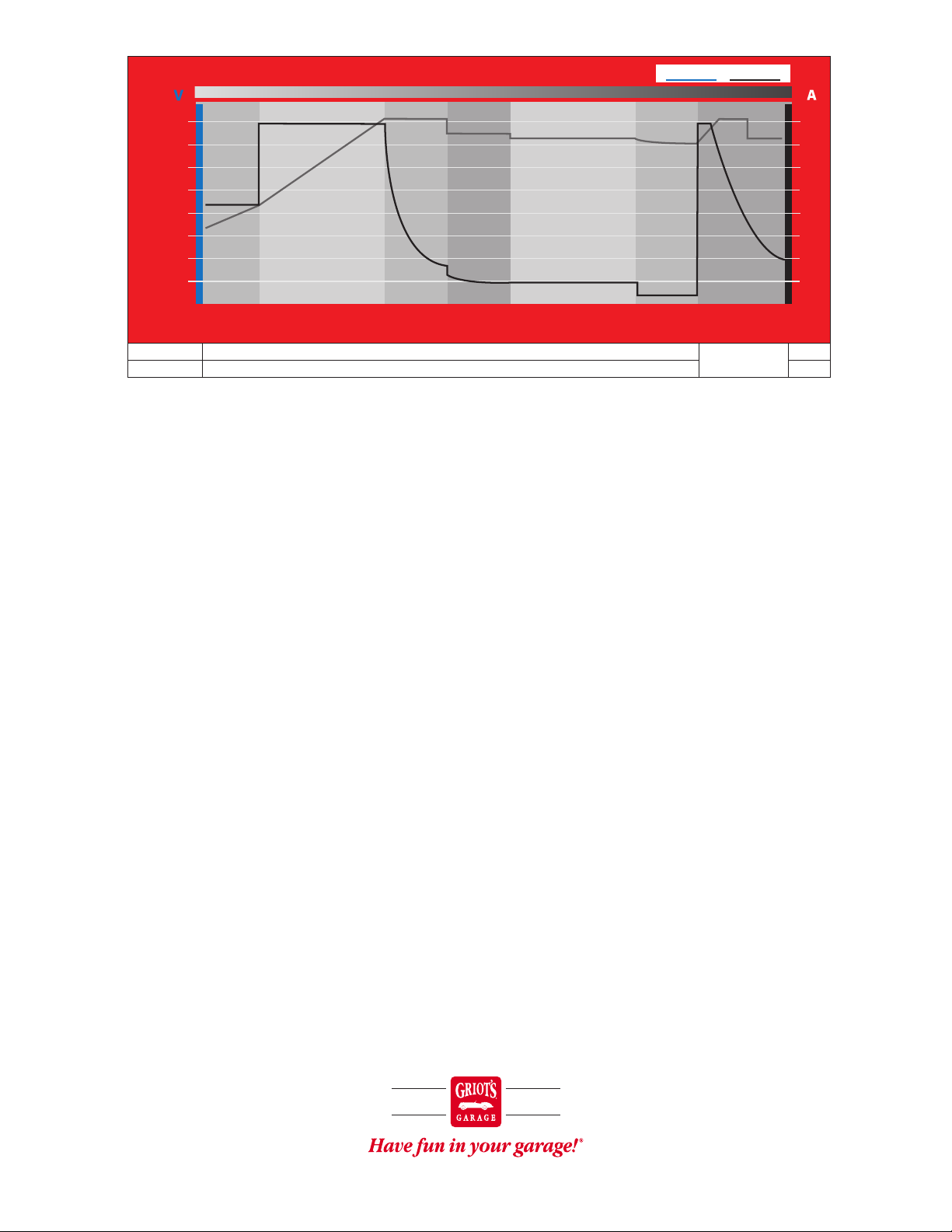
>>> SEE MULTI-PHASING CHART ON BACK PAGE <<<
BATTERY MANAGER V FEATURES
The charger uses a proprietary Multi-Stage charging process
designed to optimally charge and maintain batteries.
• Energizing Phase
The charging process includes an initial energizing mode in which
the charger determines the best charging path for the connected
battery. The charger then enters the Fast Charge stage (most cases),
Soft Start Mode, Battery Recondition Mode or stops the charging
routine because unsafe battery conditions (short, etc.) are detected.
• Soft Start Mode
Soft Start Mode is activated when the charger is connected to a
deeply discharged battery. This mode protects the battery during
the initial charge period, as the battery's voltage rises to a more
normal level, and is beneficial for the long-term health of the
battery.
• Battery Reconditioning Mode
During the Energizing Phase, if the charger detects the presence
of battery sulfation, it will activate this mode. If this occurs, the
CHARGING LED will flash. This indicates the charge time will be
extended while the charger attempts to recondition the battery.
• Ideal Battery Maintenance
A key feature of this charger is how it manages a battery that
remains on the charger after a complete charge has been achieved,
such as during the storage of a seasonal use vehicle. Once the
charger reaches the Resting Phase, its output is virtually turned off,
except to occasionally monitor battery condition. This is beneficial
for the connected battery, as it reduces chemical reaction within
the battery compared to traditional charger maintenance modes.
This greatly reduces the chance of damaging a battery in long-term
storage. In addition, during the exercising phase, it introduces a load
on the battery, simulating active use and recharges the battery to full
charge. This Exercising feature keeps the battery in optimal condition
during periods of storage and non-use.
• Compatible With Multiple Battery Types
The charger will properly charge a wide variety of battery types,
including Conventional, Maintenance-Free, AGM, Spiral Wound,
Depp Cycle, Marine and LiFePO4 Lithium batteries.
• Smart Clamp Technology
The charger will send power to the output leads only when a
proper battery connection is made.
• Reverse Polarity Protection
Guards against reverse connections. POLARITY LED will light on
control panel and power will not be sent to output cables if a
reverse connection is sensed.

• Temperature Compensation
The charger is equipped with temperature compensation
technology, which alters the charging parameters based on
ambient temperature. This is beneficial for battery health, as it is
critical in achieving an optimal charge because the battery’s needs
change based on temperature.
• Battery Fault Protection
Guards against excessively charging compromised batteries.
ERROR and CHARGING LED will flash indicating charging has
stopped and the charger has detected a compromised battery.
Conditions that cause this error include: if the battery voltage does
not rise appropriately during the charging process (indicating a
shorted cell) or if the maximum charge time has been exceeded.
• Short Circuit Protection
Guards against shorted connections. ERROR LED will light solid
on control panel and power will not be sent to output cables. This
condition is triggered if the charger detects less than 1V across
the clamps. See Operating Instructions Step 3 Note 2 for details
regarding this feature.
• Over-Voltage Protection
Guards against charging errors where the charger is programmed
to charge in a different voltage than the detected voltage of the
battery. When this safeguard is engaged, the ERROR indicator
will light. To reset the charger, disconnect from AC outlet, reset the
vehicle connections and reconnect to the AC outlet.
• Recovery Mode
The charger is equipped with the ability to react to the interruption
of power (power outage) in two different ways.
The factory default setting is Recovery Mode ON, under which
the charger will continue to monitor the battery during a power
outage situation and resume charging under the existing charging
parameters upon the resumption of AC power. This feature is best
utilized during periods when occasional monitoring of the charger
is not possible, such as when you are on vacation.
You can switch to Recovery Mode OFF, which turns the charger OFF
if there is any interruption of AC input power. So, if the power goes
out, the charger will stop charging and enter Standby Mode, with
default settings, upon the resumption of AC power.
To switch Recovery Mode from OFF to ON or ON to OFF, press and
hold both the Battery Type and CHARGE button and push the
Voltage Selection button twice. Recovery Mode status is indicated
by the RM LED – when the RM LED is lit, Recovery is ON.
When the charger is in Recovery Mode ON and a power interruption
occurs, all charger status LEDs will turn off, except the RM LED,
which will blink. After 36 hours, to conserve the charge on the
connected battery, all LEDs will turn off. Upon resumption of power,
the charger will resume normal operation in the existing settings
and status indicators will again be active.
• Low Energy Consumption Mode
The charger is designed to minimize energy consumption as much
as possible. Once a charging routine is initiated, if the unit is left for
10+ minutes without a key pressed, the POWER LED will illuminate
solid and all other lights will turn off. The unit is still functioning
and detecting what the battery needs but is now in Low Energy
Consumption Mode. At any time, you can wake the display by
pressing any button one time.
VOLTAGE CURRENT
MULTI-PHASE CHARGING PROCESS
TIME ELAPSED
Phase 1
Energizing
Phase 2
Fast Charge
Phase 3
Absorption
Phase 4
Completion
Phase 5
Resting
Phase 6
Exercising
Phase 7
Restoring
CONSTANT
VOLTAGE
CONSTANT
CURRENT
DISPLAY = EP
See Phases 2 - 4
Indicators
Flashing
Flashing
Off
Slowly Flashing
On
Off
On
Off
On
Off
Flashing
On
Charging LED
Complete LED
4.0
3.5
3.0
2.5
2.0
1.5
1.0
0.0
-1.0
14
12
10
8
6
4
2
0
ANSWERS TO YOUR QUESTIONS
Should you have any comments or questions about the use of your Battery Manager V, our Customer Service Department
can be reached by phone at 800-345-5789 or by email at info@griotsgarage.com.
100% Guaranteed
Learn about our full line of premium car care products at griotsgarage.com
© Griot’s Garage Inc., 3333 S. 38th St., Tacoma, WA 98409 | 800-345-5789
This manual suits for next models
1
Other Griots Garage Batteries Charger manuals