Grizzly G0602 User manual

WARNING: NO PORTION OF THIS MANUAL MAY BE REPRODUCED IN ANY SHAPE
OR FORM WITHOUT THE WRITTEN APPROVAL OF GRIZZLY INDUSTRIAL, INC.
LubricationMAINTENANCE Page 34
If you have any questions about this manual insert or machine lubrication and break-in, please contact
MODEL G0602
10" X 22" BENCHTOP
LATHE
MANUAL INSERT
GEARBOXES MUST
BE FILLED WITH OIL!
NO OIL SHIPPED WITH
MACHINE!
Requires Mobil® DTE®
Heavy-Medium
or
an equivalent oil.

COPYRIGHT © NOVEMBER, 2006 BY GRIZZLY INDUSTRIAL, INC. REVISED APRIL 2007.
WARNING: NO PORTION OF THIS MANUAL MAY BE REPRODUCED IN ANY SHAPE
OR FORM WITHOUT THE WRITTEN APPROVAL OF GRIZZLY INDUSTRIAL, INC.
#CR8520 PRINTED IN CHINA
MODEL G0602
10" X 22" BENCHTOP LATHE
OWNER'S MANUAL


G0602 10" X 22" Benchtop Lathe -1-
INTRODUCTION ............................................... 2
Foreword ........................................................ 2
Contact Info ................................................... 2
Machine Data Sheet ...................................... 3
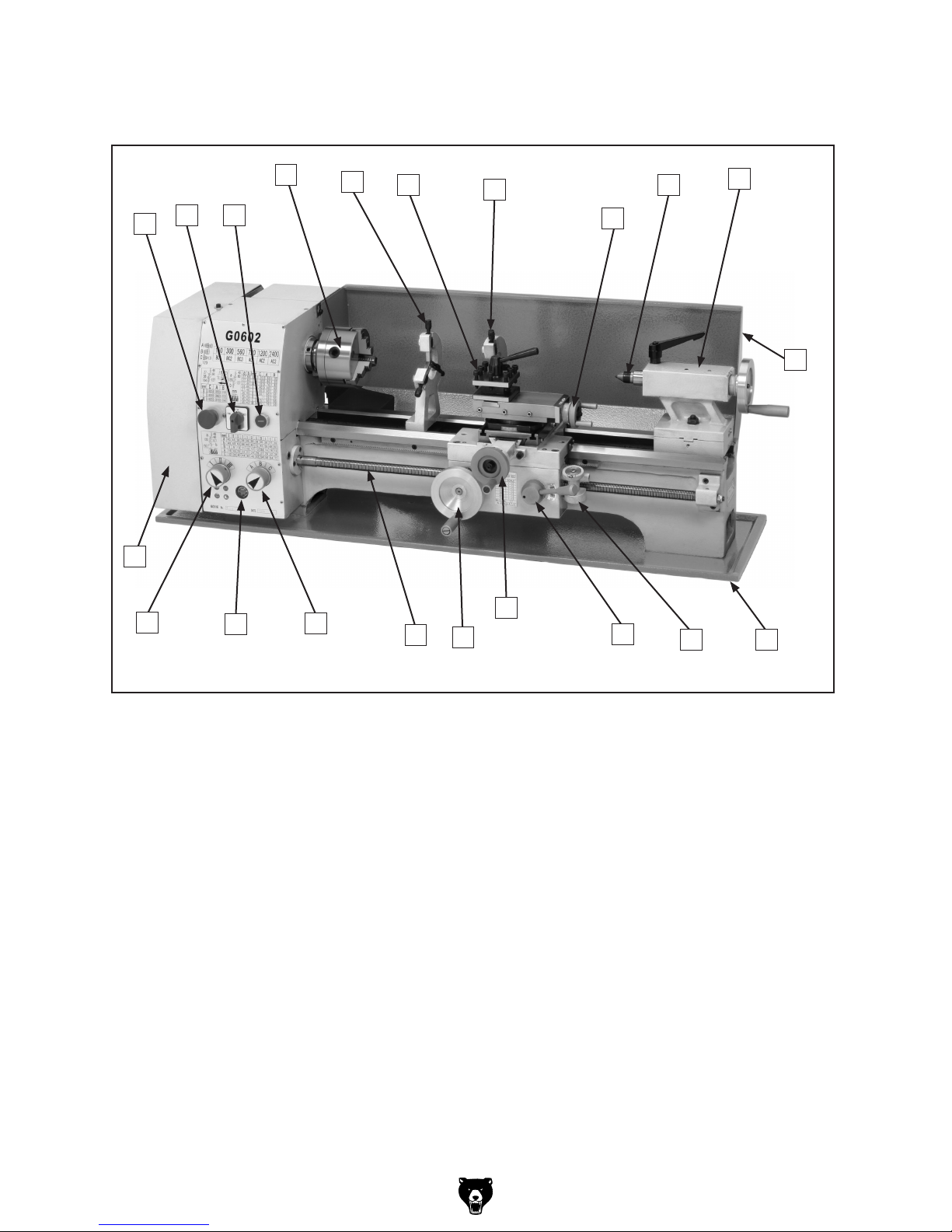
Identification ................................................... 5
SECTION 1: SAFETY ....................................... 6
Additional Safety Instructions for Lathes ....... 8
Glossary of Terms ......................................... 9
SECTION 2: CIRCUIT REQUIREMENTS ...... 10
110V Operation ............................................ 10
SECTION 3: SET UP ...................................... 11
Unpacking .................................................... 11
Inventory ...................................................... 12
Site Considerations ...................................... 13
Clean Up ...................................................... 13
Test Run & Break-In ................................... 14
SECTION 4: OPERATIONS ........................... 15
Operation Safety .......................................... 15
Power Supply ............................................... 15
Mounting Chuck or Faceplate ................... 16
Replacing Jaws ............................................ 17
Four-Jaw Chuck ........................................... 18
Faceplate ..................................................... 19
Tailstock ....................................................... 20
Drilling with the Tailstock ............................. 20
Cutting Shallow Tapers with Tailstock ......... 21
Aligning Tailstock ........................................ 21
Centers ........................................................ 23
Steady Rest ................................................. 24
Follow Rest .................................................. 24
Compound Rest ........................................... 25
Tool Post ...................................................... 25
Manual Feed Handwheels ........................... 26
Determining Correct Spindle RPM .............. 27
Setting Spindle ............................................ 28
RPM ............................................................. 28
Setting the Power Feed Rate ...................... 29
Inch Threads ................................................ 30
Metric Threads ............................................. 31
SECTION 5: ACCESSORIES ......................... 32
SECTION 6: MAINTENANCE ......................... 34
Basic Maintenance ...................................... 34
General Lubrication ..................................... 34
Belt Adjustment or Replacement ................. 35
SECTION 7: SERVICE ................................... 36
Troubleshooting ........................................... 36
Cross Slide Backlash Adjustment ................ 38
Gib Adjustments .......................................... 38
Electrical Component Connections .............. 39
Wiring Diagram ............................................ 40
SECTION 8: PARTS ....................................... 41
Spindle and Drive Belt ................................. 41
Apron ........................................................... 43
Tool Holder and Compound Rest ................ 44
Tailstock ....................................................... 45
Bed and Leadscew ...................................... 46
Steady Rest and Follow Rest ...................... 47
Motor and Electrical ..................................... 48
Gearbox Diagram A ..................................... 49
Gearbox Diagram B ..................................... 50
Cross Feed and Carriage ............................ 52
WARRANTY AND RETURNS ........................ 54
Table of Contents

-2- G0602 10" X 22" Benchtop Lathe
If you have any comments regarding this manual,
please write to us at the address below:
Grizzly Industrial, Inc.
C/O Technical Documentation Manager
P.O. Box 2069
Bellingham, WA 98227-2069
Email: [email protected]
We stand behind our machines. If you have any
service questions or parts requests, please call or
write us at the location listed below.
Grizzly Industrial, Inc.
1203 Lycoming Mall Circle
Muncy, PA 17756
Phone: (570) 546-9663
Fax: (800) 438-5901
E-Mail: [email protected]
Web Site: http://www.grizzly.com
Foreword
INTRODUCTION
Contact Info
We are proud to offer the Model G0602 10" X 22"
Benchtop Lathe. This machine is part of a grow-
ing Grizzly family of fine metalworking machinery.
When used according to the guidelines set forth in
this manual, you can expect years of trouble-free,
enjoyable operation and proof of Grizzly’s com-
mitment to customer satisfaction.
We are pleased to provide this manual with
the Model G0602. It was written to guide you
through assembly, review safety considerations,
and cover general operating procedures. It repre-
sents our effort to produce the best documenta-
tion possible.
The specifications, drawings, and photographs
illustrated in this manual represent the Model
G0602 as supplied when the manual was pre-
pared. However, owing to Grizzly’s policy of con-
tinuous improvement, changes may be made at
any time with no obligation on the part of Grizzly.
For your convenience, we always keep current
Grizzly manuals available on our website at www.
grizzly.com. Any updates to your machine will be
reflected in these manuals as soon as they are
complete. Visit our site often to check for the lat-
est updates to this manual!

G0602 10" X 22" Benchtop Lathe -3-
Machine Data Sheet
MODEL G0602 10" X 22" BENCHTOP LATHE
Customer Service #: (570) 546-9663 • To Order Call: (800) 523-4777 • Fax #: (800) 438-5901
MACHINE DATA
SHEET
General Specifications:
Machine Weight ..............................................................................................................................................330 lbs.
Overall Dimensions .................................................................................................32" Deep x 50" Long x 165⁄8" Tall
Footprint ................................................................................................................................ 121⁄2" Deep x 471⁄2" Long
Shipping Information:
Shipping Weight ..............................................................................................................................................440 lbs.
Crate Size ...................................................................................................................................551⁄4" x 221⁄2" x 221⁄4"
Electrical:
Power OFF Switch .................................................................... Emergency Push-button Kill Switch w/Manual Reset
Power ON Switch ......................................................................................................................................Push Button
Motor Direction Rotary Switch .................................................................................... 3-Position (FWD, STOP, REV)
Motor Control .......................................................................................................................Magnetic Contactor 110V
Switch Voltage ................................................................................................................................................110VAC
Cord Length ........................................................................................................................................................ 5 feet
Cord Gauge .................................................................................................................................................. 14 gauge
Recommended Breaker Size .................................................................................................................................20A
Plug ........................................................................................................................................................................ Yes
Motor:
Lathe Motor
Type................................................................................Reversible TEFC Capacitor Start and Run Induction
Horsepower ................................................................................................................................................ 1 HP
Voltage.......................................................................................................................................................110V
Phase ....................................................................................................................................................... Single
Amps .........................................................................................................................................................13.6A
Speed ................................................................................................................................................ 1725 RPM
Cycle .........................................................................................................................................................60 Hz
Power Transfer .....................................................................................................................Cogged-Belt Drive
Bearings ...................................................................................................................... Shielded and Lubricated
Lathe Information
Spindle Bore ............................................................................................................................................................. 1"
Spindle Taper ..................................................................................................................................................... MT #4
Tailstock Taper .................................................................................................................................................. MT #3
Tailstock Barrel Travel ........................................................................................................................................... 21⁄2"
Speeds .......................................................................................................150, 300, 560, 720, 1200, and 2400 RPM
Compound Slide Travel ......................................................................................................................................... 31⁄2"
Cross Slide Travel .................................................................................................................................................. 61⁄2"
Carriage Travel .................................................................................................................................................... 181⁄2"
Thread Range (inches) ........................................................................................................................33 @ 8–72 TPI
Thread Range (metric) .................................................................................................................. 26 @ 0.25–3.5 mm
Longitude Feed ......................................................................................................................... 9 @ 0.0023-0.013 r⁄inch
Lead Screw ............................................................................................................................................... 3⁄4" x 12 TPI
Swing Over Bed ..................................................................................................................................................... 95⁄8"
Swing Over Cross Slide ......................................................................................................................................... 61⁄8"
Distance Between Centers ..................................................................................................................................... 22"
Spindle Thread .......................................................................................................................................... 13⁄4" x 8 TPI
Maximum Tool Size .........................................................................................................................................1⁄2" x 1⁄2"

-4- G0602 10" X 22" Benchtop Lathe
Other Specifications:
Country of Origin .................................................................................................................................................China
Warranty .............................................................................................................................................................1 Year
Serial Number Location .......................................................................................................Data Label on Headstock
Features:
4-Jaw Chuck .......................................................................................................................................................... 61⁄2"
3-Jaw Chuck .............................................................................................................................. w/Int. & Ext. Jaws, 5"
Faceplate ................................................................................................................................... w/Int. & Ext. Jaws, 8"
Tool Holder .............................................................................................................................4-Way Turret Tool Post
Change Gears ...................................................................................................................................................... Steel
Dead Center ........................................................................................................................................................ MT#3
Tool Box w/Tool Kit ......................................................................................................................................................
Steady Rest .................................................................................................................................................................
Follow Rest ..................................................................................................................................................................
Chip Tray .....................................................................................................................................................................
Back Splash .................................................................................................................................................................
Oil Lubricated Gearbox ................................................................................................................................................

G0602 10" X 22" Benchtop Lathe -5-
Identification
L. Chip Tray
M. Thread Dial
N. Half Nut Lever
O. Cross Feed Handwheel
P. Carriage Feed Handwheel
Q. Lead Screw
R. Threading Dial (Alpha)
S. Gearbox Oil Level Sight Glass
T. Threading Dial (Numeric)
U. Change Gear and Belt Safety Cover
A. Emergency Stop Button Switch
B. Motor Direction Selector Switch
C. Power ON Push Button Switch
D. 3-Jaw Chuck
E. Steady Rest
F. 4-Way Tool Holder
G. Follow Rest
H. Compound Rest Handwheel
I. MT#3 Dead Center
J. Tailstock
K. Back Splash
U
TSRQP
O
NM L
K
J
I
H
G
F
E
D
CB
A

-6- G0602 10" X 22" Benchtop Lathe

G0602 10" X 22" Benchtop Lathe -7-

-8- G0602 10" X 22" Benchtop Lathe
No list of safety guidelines can be complete.
Every shop environment is different. Always
consider safety first, as it applies to your
individual working conditions. Use this and
other machinery with caution and respect.
Failure to do so could result in serious per-
sonal injury, damage to equipment, or poor
work results.
Like all machinery there is potential danger
when operating this machine. Accidents are
frequently caused by lack of familiarity or
failure to pay attention. Use this machine
with respect and caution to lessen the pos-
sibility of operator injury. If normal safety
precautions are overlooked or ignored, seri-
ous personal injury may occur.
1. UNDERSTANDING THE MACHINE: Read
and understand this manual before operat-
ing machine.
2. CLEANING MACHINE: To avoid entangle-
ment and lacerations, do not clear chips by
hand. Use a brush, and never clear chips
while the lathe is operating.
3. USING CORRECT TOOLING: Always select
the right cutter for the job, and make sure
cutters are sharp. The right tool decreases
strain on the lathe components and reduces
the risk of unsafe cutting.
4. ELIMINATING A PROJECTILE HAZARD:
Always remove the chuck key, and never
walk away from the lathe with the chuck key
installed.
5. SECURING A WORKPIECE: Make sure
workpiece is properly held in chuck before
starting lathe. A workpiece thrown from the
chuck could cause severe injury.
6. AVOIDING OVERLOADS: Always use the
appropriate feed and speed rates.
7. MAINTAINING A SAFE WORKPLACE:
Never leave lathe unattended while it is run-
ning.
8. PREVENTING A CUTTING TOOL -CHUCK
CRASH: Always release automatic feeds
after completing a job.
9. AVOIDING STARTUP INJURIES: Make
sure workpiece, cutting tool, and tool post
have adequate clearance before starting
lathe. Check chuck clearance and saddle
clearance before starting the lathe. Make
sure spindle RPM is set correctly for part
diameter before starting the lathe. Large
parts can be ejected from the chuck if the
chuck speed is set too high.
10. CHUCK SAFETY: Chucks are surprisingly
heavy and awkward to hold, so protect your
hands and the lathe ways. Always use a
chuck cradle or piece of plywood over the
lathe ways.
11. WORKPIECE SUPPORT: Support a long
workpiece if it extends from the headstock
so it will not wobble violently when the lathe
is turned ON. If workpiece extends more
than 2.5 times its diameter from the chuck,
support it by a center or steady rest, or it
may deflect and fall out of the chuck while
cutting.
12. AVOIDING ENTANGLEMENT INJURIES:
Never attempt to slow or stop the lathe
chuck or mill spindle by hand; and tie back
long hair, ponytails, loose clothing, and
sleeves so they do not dangle.
Additional Safety Instructions for Lathes

G0602 10" X 22" Benchtop Lathe -9-
The following is a list of common definitions, terms and phrases used throughout this manual as they relate
to this lathe and metalworking in general. Become familiar with these terms for assembling, adjusting or
operating this machine. Your safety is VERY important to us at Grizzly!
Arbor: A machine shaft that supports a cutting
tool.
Backlash: Wear in a screw or gear mechanism
that may result in slippage, vibration, and loss
of tolerance.
Carriage: A main housing that consists of the
apron and the saddle.
Cross Slide: A fixture attached to the lathe car-
riage that holds the compound rest and can be
moved in and out.
Compound Rest: A fixture attached to the cross
slide that holds the tool holder and can be
moved in and out.
Cutting Speed: The distance a point on a cutter
moves in one minute, expressed in meters or
feet per minute.
Dial Indicator: An instrument used in setup
and inspection work that shows on a dial the
amount of error in size or alignment of a part.
Dividing Head: A milling machine accessory
used to divide a circular object into a number
of equal parts.
Down Milling or Climb Milling: Feeding the
workpiece in the same direction as the cutter
rotation.
Facing: In lathe work, cutting across the end of a
workpiece, usually to machine a flat surface.
Feed: The movement of a cutting tool into a
workpiece.
Fixture: A device that securely holds the
workpiece in place during cutting operation
as opposed to a jig which is used to hold and
guide a workpiece through an operation.
Gib: A tapered wedge located along a sliding
member to take up wear or to ensure a proper
fit.
Headstock: The major lathe component that
houses the spindle and motor drive system to
turn the workpiece.
Lathe Center: A lathe accessory with a 60°
point which is inserted into the headstock or
tailstock of the lathe and is used to support the
workpiece.
Leadscrew: Lathe—The long screw that is driv-
en by the end gears and supplies power to the
carriage. Mill—The screws that move the table
in longitudinal, transverse, or vertical direc-
tions.
Saddle: The upper portion of carriage that rides
on the lathe ways and supports the cross feed
and the follow rest.
Spindle: The revolving shaft that holds and
drives the workpiece or cutting tool.
Tailstock: A moveable fixture opposite of the
headstock on a lathe that has a spindle used
to support one end of a workpiece and for hold-
ing tools.
Tool Post: The part of the compound rest that
holds the tool holder.
Turret: Lathe—A machine fixture that holds mul-
tiple tools and can be revolved and indexed to
position. Mill—The part of a mill which rotates
on the column and can be set to a specific
degree.
Ways: The precision machined and flat tracks on
a lathe or mill on which the carriage, tailstock,
and the mill table and knee slide.
Glossary of Terms

-10- G0602 10" X 22" Benchtop Lathe
Serious personal injury could occur if you
connect the machine to the power source
before you have completed the set up pro-
cess. DO NOT connect the machine to the
power source until instructed to do so.
110V Operation
Amperage Draw
The Model G0602 motor draws the following
amps under maximum load:
Motor Draw ......................................... 13.6 Amps
Circuit Recommendations
We recommend connecting your machine to a
dedicated and grounded circuit that is rated for
the amperage given below. Never replace a circuit
breaker on an existing circuit with one of higher
amperage without consulting a qualified electri-
cian to ensure compliance with wiring codes. If
you are unsure about the wiring codes in your
area or you plan to connect your machine to a
shared circuit, consult a qualified electrician.
110V Circuit ........................................... 20 Amps
This machine must have a ground prong in
the plug to help ensure that it is grounded.
DO NOT remove ground prong from plug
to fit into a two-pronged outlet! If the plug
will not fit the outlet, have the proper outlet
installed by a qualified electrician.
Extension Cords
We do not recommend the use of extension cords,
but if you find it absolutely necessary:
• Use at least a 12 gauge cord that does not
exceed 50 feet in length!
• The extension cord must also contain a
ground wire and plug pin.
• A qualified electrician MUST size cords over
50 feet long to prevent motor damage.
SECTION 2: CIRCUIT REQUIREMENTS
Electrocution or fire could
result if this machine is
not grounded correctly or
if your electrical configu-
ration does not comply
with local and state codes.
Ensure compliance by
checking with a qualified
electrician!

G0602 10" X 22" Benchtop Lathe -11-
SECTION 3: SET UP
The Model G0602 weighs approximately
440 lbs. DO NOT attempt to lift and position
this machine without using power lifting
equipment. Inspect all lifting equipment
and make sure that all is in perfect work-
ing order and is rated for the load before
attempting to lift and move this lathe.
Ignoring this warning may lead to serious
personal injury or death.
The Model G0602 was carefully packed when it
left our warehouse. If you discover the machine
is damaged after you have signed for delivery,
please immediately call Customer Service at
(570) 546-9663 for advice.
Save the containers and all packing materials for
possible inspection by the carrier or its agent.
Otherwise, filing a freight claim can be difficult.
When you are completely satisfied with the condi-
tion of your shipment, inventory the contents.
Unpacking

-12- G0602 10" X 22" Benchtop Lathe
After all the parts have been removed from your
shipment, you should have the following items:
Installed Accessories (Figure 1) .................... Qty.
A. 5" Three-Jaw Chuck ..................................... 1
B. Steady Rest .................................................. 1
C. 4-Way Tool Post and Compound Rest ........ 1
D. Compound Slide ........................................... 1
Packaged Accessories (Figure 2)
E. Hex Wrench Set (2.5, 3, 4, 5, 6 mm) ..... 1 EA
F. Tool Box .......................................................1
G. 8" Faceplate ................................................. 1
H. 61⁄2" Four-Jaw Universal Chuck .................... 1
I. Low Range Belt ............................................ 1
High Range Belt (Installed) .......................... 1
J. #2 Phillips and Standard Screwdriver .... 1 EA
K. Wrench Set (12/14, 12/14, 19/17 mm) ... 1 EA
L. Three-Jaw Chuck Internal Jaw Set .............. 1
M. Three-Jaw Chuck Key .................................. 1
N. Four-Jaw Chuck Key .................................... 1
O. Oil Bottle ....................................................... 1
P. Cross Feed Handle ...................................... 1
Q. Carriage Feed Handle .................................. 1
R. Dead Center MT#3 ...................................... 1
S. Change Gear Set ......................................... 1
— Change Gear (27-tooth, Installed) ........... 1
— Change Gear (36-tooth) .......................... 1
— Change Gear (40-tooth) .......................... 1
— Change Gear (44-tooth) .......................... 1
— Change Gear (46-tooth) .......................... 1
— Change Gear (48-tooth, Installed) ........... 1
— Change Gear (52-tooth) .......................... 1
— Change Gear (45-tooth) .......................... 1
— Change Gear (56-tooth, Installed) ........... 1
— Change Gear (60-tooth) .......................... 1
— Plastic Drive Gear (60-tooth, Installed) ... 1
— Change Gear (104-tooth, Installed) ......... 1
— Change Gear (120-tooth) ........................ 1
— Change Gear (127-tooth, Installed) ......... 1
Figure 1. Installed accessories.
D
ABC
Inventory
In the event that any nonproprietary parts are
missing (e.g. a nut or a washer), we would be
glad to replace them, or for the sake of expedi-
ency, replacements can be obtained at your local
hardware store.
NOTICE
Some hardware/fasteners on the inventory
list may arrive pre-installed on the machine.
Check these locations before assuming that
any items from the inventory list are miss-
ing.
Figure 2. Packaged accessories.
F
G
H
I
JKLMN
O
P
RS
E
Q

G0602 10" X 22" Benchtop Lathe -13-
Workbench and Floor Load
Your lathe is a heavy load (330 lbs.) distributed over
a small footprint. Bolt it to a workbench, cabinet, or
machine table that can support the machine and the
workpiece. If there is any tipping risk, bolt the work-
bench, cabinet, or machine table to the shop floor.
Make sure the floor will hold the accumulated load of
the machine, workpiece, workbench, and operator.
Placement Location
Consider existing and anticipated needs, motor
access, length of rods to be loaded into the lathe,
and space for auxiliary stands, work tables or other
machinery when establishing a location for your
lathe (see Figure 3 for minimum wall clearances).
The ways and other unpainted parts of your lathe
are coated with a waxy grease that protects
them from corrosion during shipment. Clean this
grease off with a solvent cleaner or citrus-based
degreaser. DO NOT use chlorine-based sol-
vents such as brake parts cleaner, lacquer thin-
ner, or acetone—if you happen to splash some
onto a painted surface, you will ruin the finish.
Figure 3. Mounting bolt pattern and minimum working clearances.
Unsupervised children and
visitors inside your shop
could cause serious per-
sonal injury to themselves.
Lock all entrances to the
shop when you are away and
DO NOT allow unsupervised
children or visitors in your
shop at any time!
Site Considerations Clean Up
Gasoline and petroleum
products ignite easily.
DO NOT use gasoline or
petroleum products to
clean the machinery.
Many of the solvents
commonly used to clean
machinery can be toxic
when inhaled or ingest-
ed. Lack of ventilation
while using these sol-
vents could cause seri-
ous personal health risks
or fire. Take precautions
from this hazard by only
using cleaning solvents
in a well ventilated area.

-14- G0602 10" X 22" Benchtop Lathe
5. Move the numeric gearbox dial to I, and the
alpha gearbox dial to C, (see Figure 5).
Note: You may have to slightly rotate the
chuck by hand to engage the gears.
6. Push the green power button, then turn
the selector to FWD. The top of the chuck
should now be turning toward you.
7. Push the emergency stop button. The lathe
should stop. If not, disconnect power and
refer to Troubleshooting on Page 35.
8. Return the selector to STOP, reset the emer-
gency stop button, restart the lathe, and let
the lathe run for a minimum of 10 minutes.
—If you hear squealing or grinding noises,
turn the lathe OFF immediately and cor-
rect any problem before further operation.
—If the problem is not readily apparent,
refer to Troubleshooting on Page 35.
9. Turn the lathe OFF, disconnect power, and
move the drive belt to the next highest RPM
and run the lathe for 10 minutes.
10. Repeat Step 9 for the rest of the speeds
progressively increasing the speed. When
you are complete, the lathe is broken in.
11. Change the lubricant in the headstock with
Mobil DTE® Oil or an equivalent, and re-lubri-
cate the lathe. Refer to General Lubrication
on Page 33 for steps and locations.
Test Run & Break-In
The purpose of the test run is to make sure the
lathe and safety features operate correctly before
proceeding with additional setup.
To begin the test run & break-in procedure:
1. Make sure the lathe is lubricated and the
headstock oil level is full. Refer to General
Lubrication on Page 33.
2. Make sure the chuck is correctly secured to
the spindle. Refer to Mounting Chuck or
Faceplate on Page 16 for details.
3. Change the belt position so the spindle will
rotate at 150 RPM, and disengage the half
nut with the lever shown in Figure 4. Refer
to Setting the Spindle RPM on Page 26 for
clarification.
Motor Direction Selector
Pointing to STOP
Emergency
Stop Button
Figure 5. Headstock and gearbox controls.
Make sure the half nut lever is disengaged
before you start the lathe! Thoroughly
familiarize yourself with all the controls and
their functions before using the longitudinal
feed! NEVER SHIFT LATHE GEARS WHEN
MACHINE IS OPERATING.
NOTICE
Figure 4. Half nut lever in the disengaged
position.
Half-Nut
Lever Pulled Up
(Disengaged)
4. Rotate the red emergency stop button (Figure
5) clockwise so it pops out, and make sure
the motor direction selector points to STOP.
Numeric
Dial Alpha
Dial

G0602 10" X 22" Benchtop Lathe -15-
Pressing the red emergency stop button (Figure
6) cuts power to the machine. Twisting the emer-
gency stop button clockwise and letting it pop
out resets the lathe, so when you push the green
power ON button lathe operations can begin
again.
Disconnect power to the lathe, and make sure
the spindle is stopped before proceeding
with any adjustments or maintenance.
Failure to comply may result in serious
personal injury or death.
Figure 6. Lathe electrical controls.
Emergency
Stop Button
Power ON
Button
Motor
Direction
Switch
Operation Safety
SECTION 4: OPERATIONS
Power Supply
Damage to your eyes, lungs, and ears could
result from using this machine without
proper protective gear. Always wear safety
glasses, a respirator, and hearing protection
when operating this machine.
Loose hair and cloth-
ing could get caught in
machinery and cause seri-
ous personal injury. Keep
loose clothing and long
hair away from moving
machinery.
NOTICE
If you have never used this type of machine
or equipment before, WE STRONGLY REC-
OMMEND that you read books, trade maga-
zines, or get formal training before begin-
ning any projects. Regardless of the con-
tent in this section, Grizzly Industrial will
not be held liable for accidents caused by
lack of training.
Complete the Test Run & Break-In proce-
dure on Page 14 before using this lathe for
any cutting or threading operations; other-
wise, gear box damage will occur.
NOTICE

-16- G0602 10" X 22" Benchtop Lathe
Mounting Chuck or
Faceplate
4. Insert the chuck wrenches as shown in
Figure 8, and hold the spindle and loosen
the chuck.
Note: The chuck loosens in the counter-
clockwise direction.
The three-jaw scroll chuck will automatically self-
center the workpiece. It has hardened steel exter-
nal jaws that hold the workpiece on the outside
diameter of the part. An extra set of jaws is includ-
ed for holding larger workpieces on the inside
diameter of the part.
The four-jaw chuck has hardened steel jaws
that must be independently adjusted to center
the workpiece. Each jaw can be removed from
the chuck body and reversed for clamping odd-
shaped workpieces.
If either chuck cannot hold your workpiece, the
cast-iron faceplate has slots for T-bolts that hold
standard or custom clamping fixtures. With the
correct clamping hardware, this faceplate will hold
non-cylindrical parts such as castings.
Both chucks and the faceplate are removed and
installed the same way.
To remove and install the chuck or faceplate:
1. DISCONNECT POWER TO THE LATHE!
2. Lay a piece of plywood over the bedways to
protect the precision-ground way surfaces.
3. Use a 5mm hex wrench to remove the two
cap screws and the chuck locks (Figure 7).
Figure 8. Inserting chuck keys to loosen or
tighten the chuck onto the spindle.
Figure 9. Spindle.
Figure 7. Cap screw, chuck lock and lock hole.
Chuck Lock
Cap Screw
Spindle Lock Hole
5. Support the chuck from falling off of the
spindle, unscrew and remove the chuck.
6. Clean, inspect, deburr, and lightly oil all
threads and mating surfaces (Figure 9).
7. Install the faceplate or the other chuck in the
reverse order of the previous steps.
Clean, deburr, and oil threads
and all mating surfaces shown.

G0602 10" X 22" Benchtop Lathe -17-
The three-jaw scroll chuck has removable hard-
ened steel jaws (Figure 10). The outside of the
jaws are used to hold the workpiece from the outer
diameter.
Figure 10. Chuck and jaw selection.
To remove a set of jaws:
1. DISCONNECT POWER TO THE LATHE!
2. Place a piece of wood over the ways to pro-
tect them from potential damage.
3. Turn the chuck key counterclockwise and
back the jaws out.
4. Clean the jaw mating surfaces and apply a
film of white lithium grease to the mating sur-
faces.
5. Set the old jaws aside in a safe place free of
moisture and abrasives.
6. Rotate the chuck key clockwise until you see
the tip of the scroll-gear lead thread just begin
to enter jaw guide #1 (see Figure 12).
7. Insert jaw #1 into jaw guide #1 and hold the
jaw against the scroll-gear.
8. Rotate the chuck key clockwise one turn to
engage the tip of the scroll-gear lead thread
into the jaw. To verify the jaw is engaged with
the lead thread, pull on the jaw; it should be
locked into the jaw guide.
9. Install the other jaws in the same manner.
— If installed correctly, the three jaws will
converge together at the center of the
chuck.
— If the jaws do not come together, repeat
this procedure until they do.
Figure 12. Lead thread on scroll gear.
Lead Thread
Numbered from 1–3, the jaws must be used in the
matching numbered jaw guides (see Figure 11).
Figure 11. Jaw guide number.
Jaw Guide #1 Jaw Numbers
Note: The chuck need not be removed from the
spindle to swap the jaws.
Replacing Jaws
Other manuals for G0602
3
Table of contents
Other Grizzly Lathe manuals

Grizzly
Grizzly G0509 User manual

Grizzly
Grizzly G0698 User manual

Grizzly
Grizzly G8691 User manual

Grizzly
Grizzly G0625 User manual

Grizzly
Grizzly G4003G User manual

Grizzly
Grizzly G9731 User manual

Grizzly
Grizzly G0632 User manual

Grizzly
Grizzly G0579 Quick start guide

Grizzly
Grizzly G9972Z User manual

Grizzly
Grizzly G0750GV User manual

Grizzly
Grizzly G8688 User manual

Grizzly
Grizzly G9730 User manual

Grizzly
Grizzly G0670 User manual

Grizzly
Grizzly G0600 User manual

Grizzly
Grizzly G0773 User manual

Grizzly
Grizzly G0602 User manual

Grizzly
Grizzly G9972Z User manual

Grizzly
Grizzly T32794 User manual

Grizzly
Grizzly G0791 User manual

Grizzly
Grizzly G0584 User manual