Grizzly G0875 User manual

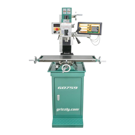
MODEL G0875
7" X 24" ENCLOSED CNC MILL
OWNER'S MANUAL
(For models manufactured since 3/19)

This manual provides critical safety instructions on the proper setup,
operation, maintenance, and service of this machine/tool. Save this
document, refer to it often, and use it to instruct other operators.
Failure to read, understand and follow the instructions in this manual
may result in fire or serious personal injury—including amputation,
electrocution, or death.
The owner of this machine/tool is solely responsible for its safe use.
This responsibility includes but is not limited to proper installation in
a safe environment, personnel training and usage authorization,
proper inspection and maintenance, manual availability and compre-
hension, application of safety devices, cutting/sanding/grinding tool
integrity, and the usage of personal protective equipment.
The manufacturer will not be held liable for injury or property damage
from negligence, improper training, machine modifications or misuse.
Some dust created by power sanding, sawing, grinding, drilling, and
other construction activities contains chemicals known to the State
of California to cause cancer, birth defects or other reproductive
harm. Some examples of these chemicals are:
• Lead from lead-based paints.
• Crystalline silica from bricks, cement and other masonry products.
• Arsenic and chromium from chemically-treated lumber.
Your risk from these exposures varies, depending on how often you
do this type of work. To reduce your exposure to these chemicals:
Work in a well ventilated area, and work with approved safety equip-
ment, such as those dust masks that are specially designed to filter
out microscopic particles.

Table of Contents
1 Safety
1.1Safety instructions for machinery ................... 5
1.2 Additional safety for CNC mills/lathes ............ 7
1.3 Safety instructions (warning notes) ................. 8
1.4 Intended use ............
....................................... 9
1.5 Reasonably foreseeable misuse
..................... 10
1.6 Possible dangers w/CNC machines ............... 10
1.7Qualification of personnel ............................... 11
1.8 User positions ................................................ 13
1.9 Safety devices ............................................... 13
1.10 Safety check .................................................. 15
1.11Safety during operation
................................ 16
1.12
Safety during maintenance
............................. 17
1.13
Disconnecting/securing CNC machine
.......... 17
1.14Unattended operation .................................... 18
1.15Accident report ................................................ 18
1.16Electronics ..................................................... 18
1.17Inspection deadlines ....................................... 19
1.18Clamping devices ................................. 19
0.1Machine data sheet ........................................ 3
2.1 Availability ...................................................... 20
2.2 Full-load current rating ................................... 20
2.3 Circuit information .......................................... 20
2.4 Circuit requirements for 220V ........................ 20
2.5 Connection type ............................................. 21
2.6Grounding instructions ................................... 21
2.7 Extension cords .............................................. 21
3.1 Scope of delivery ............................................ 22
3.2 Transport ........................................................ 22
3.3 Setup and assembly ....................................... 24
3.4 Installation plan .............................................. 26
3.5 Corrosion protection ....................................... 28
3.6 Electrical connection ....................................... 28
3.7 Refill coolant ................................................... 28
3.8 Refill central lubrication system ...................... 30
2 Power supply
3 Assembly and commissioning
5.1 Compensation of geometry ............................ 48
5.2 Coordinate systems on CNC machin
es ......... 48
5.3 NC mathematics ............................................. 51
5.4 Trigonometric functions .................................. 52
5 General information about CNC
4.1 Screen arrangement ......
................................. 33
4.2 Operating elements on the PPU ..................... 34
4.3 Elements on the MCP .................................... 39
4.4 Protection levels ............................................. 44
4 User interface, machine control panel
1.19Environmental protection ........................ 19
3.9 Warming up the machine ................................ 32
6.1Safety .......................................................... 53
6.2
Control and indicating elements
................. 53
6.3
Operational modes
...................................... 54
6.4 Programming ............
.................................... 54
6.5 Operation of the machine
............................ 55
6.6
Inserting tool
............................................... 60
6.7
Switching off CNC machine
........................ 60
6.8
Operational modes
...................................... 60
6.9
Programming
............................................. 60
6.10
Starting the program
.................................. 61
6.11Central lubrication system
......................... 61
6.12 Data interfaces and current collection
........ 62
8.1
M-function for milling machines
.................. 235
8.2
G functions to PAL
...................................... 237
6.13 Selecting the speed
................................... 62
Preparation
................................................. 65
Switch on and referencing
.......................... 71
Tool Setup
.................................................. 75
Workpiece setup
......................................... 91
7.1
7.2
7.3
7.4
Create part program: part 1
........................ 100
Create part program: part 2
........................ 116
Simulate program
....................................... 141
Test program
.............................................. 145
7.5
7.6
7.7
7.8
Machine pieces
.......................................... 149
Program restart
........................................... 155
Additional information: part 1
..................... 159
Additional information: part 2
...................... 179
7.9
7.10
7.11
7.12
Sample program
......................................... 197
ISO mode
.................................................... 210
Appendix
.................................................... 229
7.13
7.14
7.15
10
Maintenance
Operating material
...................................... 242
10.1
Safety
.......................................................... 243
10.2
Inspection and maintenance
....................... 244
10.3
Polycarbonate windows
.............................. 246
10.4
Sliding door interlock switch
........................ 247
10.5
Drain the compressed air service unit
......... 247
10.6
Recommended wearing parts
..................... 247
10.7
Cooling lubricants and tanks
....................... 248
10.8
9
Notes, messages and error messages .......... 238
8M - code list, M functions
7Brief instructions for 808D milling
6Operation
Table of Contents (Cont.)
Housing
........................................................ 253
Stand
.......................................................... 254
Base
........................................................... 255
Column
........................................................ 256
12
Parts
12.1
12.2
12.3
12.4
13
Warranty & returns
.............................................. 261
Wiring safety instructions
............................ 249
11
Wiring Diagrams
11.1
System wiring diagrams (1-2)
..................... 250
11.2
Handwheel wiring diagram
......................... 252
11.5
X/Y/Z motors wiring diagram
...................... 252
11.4
System wiring diagrams (3-4)
..................... 251
11.3
Milling head
................................................. 257
Milling table
................................................ 258
Pneumatic system
..................................... 259
Labels & cosmetics
..................................... 260
12.5
12.6
12.7
12.8

Model G0875 (Mfd. Since 3/19) -3-
Page 1 of 3Model G0875
MODEL G0875 7" X 24" ENCLOSED CNC MILL
Customer Service #: (570) 546-9663 · To Order Call: (800) 523-4777 · Fax #: (800) 438-5901
Product Dimensions:
Weight .........................................................................................................................................................................1190 lbs.
Width (side-to-side) x Depth (front-to-back) x Height .......................................................................................65 x 42 x 78 in.
Footprint (Length/Width) ............................................................................................................................................65 x 68 in.
Shipping Dimensions:
Type ........................................................................................................................................................................ Wood Crate
Content .......................................................................................................................................................................... Machine
Weight ..........................................................................................................................................................................1320 lbs.
Length x Width x Height ...............................................................................................................................71-1/2 x 46 x 85 in.
Must Ship Upright .................................................................................................................................................................Yes
Electrical:
Power Requirement ................................................................................................................................ 220V, 3-Phase, 60 Hz
Full-Load Current Rating ................................................................................................................................................... 11.8A
Minimum Circuit Size ........................................................................................................................................................... 15A
Connection Type .........................................................................................................Permanent (Hardwire to Shutoff Switch)
Power Cord Gauge ....................................................................................................................................................... 14 AWG
Motor:
Spindle
Horsepower ............................................................................................................................................................1.5 HP
Phase .......................................................................................................................................................... Single-Phase
Amps ......................................................................................................................................................................... 5.1A
Speed ...............................................................................................................................................................3000 RPM
Type ................................................................................................................................................................... DC Brush
Power Transfer .................................................................................................................................................. Belt Drive
Bearings ................................................................................................................... Shielded & Permanently Lubricated
X-Axis
Horsepower ...............................................................................................................................................................1 HP
Phase .................................................................................................................................................................. 3-Phase
Amps ......................................................................................................................................................................... 2.1A
Speed ...............................................................................................................................................................3000 RPM
Type ......................................................................................................................................................................... Servo
Power Transfer ...............................................................................................................................................Direct Drive
Bearings ......................................................................................................................Sealed & Permanently Lubricated
Y-Axis
Horsepower ...............................................................................................................................................................1 HP
Phase .................................................................................................................................................................. 3-Phase
Amps ......................................................................................................................................................................... 2.1A
Speed ...............................................................................................................................................................3000 RPM
Type ......................................................................................................................................................................... Servo
Power Transfer ...............................................................................................................................................Direct Drive
Bearings ......................................................................................................................Sealed & Permanently Lubricated

-4- Model G0875 (Mfd. Since 3/19)
Model G0875Page 2 of 3
Z-Axis
Horsepower ...............................................................................................................................................................1 HP
Phase .................................................................................................................................................................. 3-Phase
Amps ......................................................................................................................................................................... 2.1A
Speed ...............................................................................................................................................................3000 RPM
Type ......................................................................................................................................................................... Servo
Power Transfer ...............................................................................................................................................Direct Drive
Bearings ......................................................................................................................Sealed & Permanently Lubricated
Coolant Pump
Horsepower ........................................................................................................................................................ 37 Watts
Phase .......................................................................................................................................................... Single-Phase
Amps ......................................................................................................................................................................... 0.4A
Speed ...............................................................................................................................................................2800 RPM
Type ..........................................................................................................................................................TEFC Induction
Power Transfer ...............................................................................................................................................Direct Drive
Bearings ................................................................................................................... Shielded & Permanently Lubricated
Main Specifications:
Operation Information
Max Distance Spindle to Column .........................................................................................................................7-3/4 in.
Max Distance Spindle to Table ................................................................................................................................11 in.
Longitudinal Table Travel (X-Axis) ...........................................................................................................................14 in.
Cross Table Travel (Y-Axis) .......................................................................................................................................6 in.
Vertical Head Travel (Z-Axis) .....................................................................................................................................9 in.
Position Resolution ........................................................................................................................
± 0.002 in. (0.050mm)
Repeat Position Resolution ........................................................................................................... ± 0.002 in. (0.050mm)
Table Info
Table Length ......................................................................................................................................................24-3/8 in.
Table Width ................................................................................................................................................................7 in.
Table Thickness .................................................................................................................................................1-5/16 in.
Table Height (from Floor/Base) ................................................................................................................................45 in.
Table Weight Capacity ...........................................................................................................................................66 lbs.
Number of T-Slots ...........................................................................................................................................................3
T-Slot Size .............................................................................................................................................................7/16 in.
T-Slots Centers ..........................................................................................................................................................2 in.
X-Axis Rapid Feed Rate ...................................................................................................................................... 240 IPM
Y-Axis Rapid Feed Rate ...................................................................................................................................... 240 IPM
Z-Axis Rapid Feed Rate ...................................................................................................................................... 240 IPM
Spindle Info
Spindle Taper ........................................................................................................................................................... BT30
Pull Stud ..........................................................................................................................................................
BT30 x 45°
Range of Vertical Spindle Speeds ...........................................................................................................
90 - 3000 RPM
Spindle Bearings (Size & Type) ...............................................................................................Angular Contact Bearings
Fluid Capacities
Coolant Capacity ...............................................................................................................................................
5 Gallons
Construction
Spindle Housing/Quill ................................................................................................................................................Steel
Table ................................................................................................................................................................... Cast Iron
Head ................................................................................................................................................................... Cast Iron
Column/Base ...................................................................................................................................................... Cast Iron
Base ................................................................................................................................................................... Cast Iron
Stand .................................................................................................................................................................. Cast Iron
Paint Type/Finish ...................................................................................................................................................Enamel

Model G0875 (Mfd. Since 3/19) -5-
ELECTRICAL EQUIPMENT INJURY RISKS.
You can be shocked, burned, or killed by touching
live electrical components or improperly grounded
machinery. To reduce this risk, only allow qualified
service personnel to do electrical installation or
repair work, and always disconnect power before
accessing or exposing electrical equipment.
DISCONNECT POWER FIRST.
Always discon-
nect machine from power supply BEFORE mak-
ing adjustments, changing tooling, or servicing
machine. This prevents an injury risk from unin-
tended startup or contact with live electrical com-
ponents.
EYE PROTECTION. Always wear ANSI-approved
safety glasses or a face shield when operating or
observing machinery to reduce the risk of eye
injury or blindness from flying particles. Everyday
eyeglasses are NOT approved safety glasses.
OWNER’S MANUAL. Read and understand this
owner’s manual BEFORE using machine.
TRAINED OPERATORS ONLY. Untrained oper-
ators have a higher risk of being hurt or killed.
Only allow trained/supervised people to use this
machine. When machine is not being used, dis-
connect power, remove switch keys, or lock-out
machine to prevent unauthorized use—especially
around children. Make your workshop kid proof!
DANGEROUS ENVIRONMENTS. Do not use
machinery in areas that are wet, cluttered, or have
poor lighting. Operating machinery in these areas
greatly increases the risk of accidents and injury.
MENTAL ALERTNESS REQUIRED. Full mental
alertness is required for safe operation of machin-
ery. Never operate under the influence of drugs or
alcohol, when tired, or when distracted.
For Your Own Safety, Read Instruction
Manual Before Operating This Machine
The purpose of safety symbols is to attract your attention to possible hazardous conditions.
This manual uses a series of symbols and signal words intended to convey the level of impor-
tance of the safety messages. The progression of symbols is described below. Remember that
safety messages by themselves do not eliminate danger and are not a substitute for proper
accident prevention measures. Always use common sense and good judgment.
Indicates a potentially hazardous situation which, if not avoided,
MAY result in minor or moderate injury. It may also be used to alert
against unsafe practices.
Indicates a potentially hazardous situation which, if not avoided,
COULD result in death or serious injury.
Indicates an imminently hazardous situation which, if not avoided,
WILL result in death or serious injury.
Alerts the user to useful information about proper operation of the
machine to avoid machine damage.
NOTICE
Safety Instructions for Machinery
SAFETY

-6- Model G0875 (Mfd. Since 3/19)
WEARING PROPER APPAREL. Do not wear
clothing, apparel or jewelry that can become
entangled in moving parts. Always tie back or
cover long hair. Wear non-slip footwear to reduce
risk of slipping and losing control or accidentally
contacting cutting tool or moving parts.
HAZARDOUS DUST. Dust created by machinery
operations may cause cancer, birth defects, or
long-term respiratory damage. Be aware of dust
hazards associated with each workpiece mate-
rial. Always wear a NIOSH-approved respirator to
reduce your risk.
HEARING PROTECTION. Always wear hear-
ing protection when operating or observing loud
machinery. Extended exposure to this noise
without hearing protection can cause permanent
hearing loss.
REMOVE ADJUSTING TOOLS. Tools left on
machinery can become dangerous projectiles
upon startup. Never leave chuck keys, wrenches,
or any other tools on machine. Always verify
removal before starting!
USE CORRECT TOOL FOR THE JOB. Only use
this tool for its intended purpose—do not force
it or an attachment to do a job for which it was
not designed. Never make unapproved modifica-
tions—modifying tool or using it differently than
intended may result in malfunction or mechanical
failure that can lead to personal injury or death!
AWKWARD POSITIONS. Keep proper footing
and balance at all times when operating machine.
Do not overreach! Avoid awkward hand positions
that make workpiece control difficult or increase
the risk of accidental injury.
CHILDREN & BYSTANDERS. Keep children and
bystanders at a safe distance from the work area.
Stop using machine if they become a distraction.
GUARDS & COVERS. Guards and covers reduce
accidental contact with moving parts or flying
debris. Make sure they are properly installed,
undamaged, and working correctly BEFORE
operating machine.
FORCING MACHINERY. Do not force machine.
It will do the job safer and better at the rate for
which it was designed.
NEVER STAND ON MACHINE. Serious injury
may occur if machine is tipped or if the cutting
tool is unintentionally contacted.
STABLE MACHINE. Unexpected movement dur-
ing operation greatly increases risk of injury or
loss of control. Before starting, verify machine is
stable and mobile base (if used) is locked.
USE RECOMMENDED ACCESSORIES. Consult
this owner’s manual or the manufacturer for rec-
ommended accessories. Using improper acces-
sories will increase the risk of serious injury.
UNATTENDED OPERATION. To reduce the
risk of accidental injury, turn machine OFF and
ensure all moving parts completely stop before
walking away. Never leave machine running
while unattended.
MAINTAIN WITH CARE. Follow all maintenance
instructions and lubrication schedules to keep
machine in good working condition. A machine
that is improperly maintained could malfunction,
leading to serious personal injury or death.
DAMAGED PARTS. Regularly inspect machine
for damaged, loose, or mis-adjusted parts—or
any condition that could affect safe operation.
Immediately repair/replace BEFORE operating
machine. For your own safety, DO NOT operate
machine with damaged parts!
MAINTAIN POWER CORDS. When disconnect-
ing cord-connected machines from power, grab
and pull the plug—NOT the cord. Pulling the cord
may damage the wires inside. Do not handle
cord/plug with wet hands. Avoid cord damage by
keeping it away from heated surfaces, high traffic
areas, harsh chemicals, and wet/damp locations.
EXPERIENCING DIFFICULTIES. If at any time
you experience difficulties performing the intend-
ed operation, stop using the machine! Contact our
Technical Support at (570) 546-9663.

Model G0875 (Mfd. Since 3/19) -7-
Additional Safety for CNC Mills/Lathes
UNDERSTAND ALL CONTROLS. Make sure
you understand the function and proper use of all
controls before starting. This will help you avoid
making mistakes that result in serious injury.
AVOIDING ENTANGLEMENT. DO NOT wear
loose clothing, gloves, or jewelry, and tie back
long hair. Keep all guards in place and secure.
Always allow spindle to stop on its own. DO NOT
stop spindle using your hand or any other object.
EYE INJURIES. Operator and bystanders MUST
wear ANSI-approved safety glasses to help pro-
tect eyes from thrown metal shards and chips.
USE CORRECT SPINDLE SPEED. Follow rec-
ommended speeds and feeds for each size and
type of cutting tool. This helps avoid tool breakage
during operation and ensures best cutting results.
INSPECT CUTTING TOOL. Inspect cutting tools
for sharpness, chips, or cracks before each use.
Replace dull, chipped, or cracked cutting tools
immediately.
UNATTENDED MACHINE. Operator MUST be
present to immediately stop machine in case of
malfunction to prevent injury to bystanders and
machine damage.
POWER DISRUPTION. In event of power outage
during operation, turn spindle switch OFF to avoid
a possible sudden startup once power is restored.
You can be seriously injured or killed by getting clothing, jewelry, or long hair entangled with
rotating cutter/spindle. You can be severely cut or have fingers amputated from contact with
rotating cutters. You can be blinded or struck by broken cutting tools, metal chips, workpieces,
or adjustment tools thrown from the rotating spindle with great force. To reduce your risk of
serious injury when operating this machine, completely heed and understand the following:
SECURE WORKPIECE TO TABLE. Clamp work-
piece to table or secure in a vise mounted to table,
so workpiece cannot unexpectedly shift or spin
during operation. NEVER hold workpiece by hand
during operation.
DISCONNECT POWER FIRST. To reduce risk of
electrocution or injury from unexpected startup,
make sure mill/drill is turned OFF, disconnected
from power, and all moving parts have come to
a complete stop before changing cutting tools or
starting any inspection, adjustment, or mainte-
nance procedure.
CLEAN MACHINE SAFELY. Metal chips or shav-
ings can be razor sharp. DO NOT clear chips
by hand or compressed air that can force chips
farther into machine—use a brush or vacuum
instead. Never clear chips while spindle is turning.
PROPERLY MAINTAIN MACHINE. Keep
machine in proper working condition to help
ensure that it functions safely and all guards and
other components work as intended. Perform rou-
tine inspections and all necessary maintenance.
Never operate machine with damaged or worn
parts that can break or result in unexpected move-
ment during operation.
SAFE OPERATING LOCATION. DO NOT place
machine where it can be exposed to rain or mois-
ture. Exposure to water creates a shock hazard
and will reduce life of machine.

-8- Model G0875 (Mfd. Since 3/19)
1.3 Safety instructions (warning notes)
1.3.1 Classification of hazards
We classify the safety warnings into different categories. The table below gives an overview of
the classification of symbols (ideogram) and the warning signs for each specific danger and its
(possible) consequences.
1.3.2 Other pictograms
Symbol Alarm expression Definition / consequence
DANGER! Impending danger that will cause serious injury or death to people.
WARNING! A danger that can cause serious injury or death.
CAUTION! A danger or unsafe procedure that can cause personal injury or damage
to property.
ATTENTION!
A situation that could cause damage to the CNC machine, the product or
other types of damage.
No risk of injury to persons.
INFORMATION
Practical tips and other important or useful information and notes.
No dangerous or harmful consequences for people or objects.
In case of specific dangers, we replace the pictogram with
general danger with a warning of injury to hands, hazardous electrical
voltage,
rotating parts.
Activation forbidden! Do not step into the
machine!
Do not extinguish with
water!
Access forbidden!
Wear safety shoes! Use ear protection! Wear protective glasses! Read the operating instruc-
tion before commissioning!

Model G0875 (Mfd. Since 3/19) -9-
1.4 Intended use
WARNING!
In the event of improper use of the CNC machine
will endanger personnel,
the CNC machine and other material property of the operating company will be
endangered,
the correct function of the CNC machine may be affected.
The CNC machine is designed and manufactured to be used for milling and drilling cold metals
or other non-flammable materials or materials that do not constitute a health hazard by using
commercial milling and drilling tools.
Using this machine it is possible to perform dry processing as well as processing by using cool-
ing lubricants. "Cooling lubricants“ on page 242
The limit values of the balances of the tools need to be observed.
The CNC machine must only be installed and operated in a dry and well-ventilated place.
The CNC machine is designed and manufactured to be used in a non-explosive environment.
Intended useIf the CNC machine is used in any way other than described above, modified without the
approval of Grizzly Industrial, Inc., then the CNC machine is being used improperly.
We will not be held liable for any damages resulting from any operation which is not in accord-
ance with the intended use.
We expressly point out that the guarantee or CE conformity will expire, if any constructive, tech-
nicalor procedural changes are not performed by Grizzly Industrial, Inc.
It is also part of the intended use that you
the limits of performance of the CNC machine are observed,
the operating manual is observed,
the inspection and maintenance instructions are observed.
WARNING!
Extremely severe injuries due to non-intended use.
It is forbidden to make any modifications or alternations to the operation values of the
CNC machine. They could endanger the personnel and cause damage to the CNC
machine.
Warning: suspended loads! Warning of oxidizing sub-
stances!
Caution, danger of explo-
sive substances!
Warning: danger of slip-
ping!
Protect the environment! Contact address

-10- Model G0875 (Mfd. Since 3/19)
1.5 Reasonably foreseeable misuse
Any other use other than that specified under "Intended use" or any use beyond the described
use shall be deemed as non-intended use and is not permissible.
Any other use has to be discussed with the manufacturer.
It is only permissible to process metal, cold and non-inflammable materials with the milling
machine.
In order to avoid misuse, it is necessary to read and understand the operating instructions
before first commissioning.
Operators must be qualified.
1.5.1 Avoiding misuse
Use of suitable cutting tools.
Adapting the speed setting and feed to the material and workpiece.
Clamp workpieces firmly and free of vibration.
ATTENTION!
The workpiece is always to be fixed by a machine vice, jaw chuck or by another
appropriate clamping tool such as for the clamping claws.
WARNING!
Risk of injury caused by flying workpieces.
Clamp the workpiece in the machine vice. Make sure that the workpiece is firmly clamped in the
machine vice and that the machine vice is firmly clamped onto the machine table.
Use cooling and lubricating agents to increase the durability of the tool and to improve the
surface quality.
Clamp the cutting tools and workpieces on clean clamping surfaces.
Sufficiently lubricate the machine.
Set the bearing clearance and guides correctly.
ATTENTION!
Do not use the drill chuck as a milling tool. Never clamp a milling cutter into a drill
chuck. Use a collet chuck with collets for the end mill.
1.6 Possible dangers caused by the CNC machine
The CNC machine has been tested for operational safety. The construction and type are state
of the art.
Nevertheless, there is a residual risk as the CNC machine operates with
rotating parts,
electrical voltage and currents,
compressed air,
rapid moves.
We have used construction resources and safety techniques to minimize the health risk to per-
sonnel resulting from these hazards.
If the CNC machine is used and maintained by personnel who are not duly qualified, there may
be a risk resulting from incorrect or unsuitable maintenance of the CNC machine.
INFORMATION
Everyone involved in the assembly, commissioning, operation and maintenance must
be duly qualified,

Model G0875 (Mfd. Since 3/19) -11-
and strictly follow these operating instructions.
In the event of improper use
there may be a risk to personnel,
there may be a risk of damage to the CNC machine and other material values,
the correct function of the CNC machine may be affected.
Always switch off the CNC machine and disconnect it from the mains, when cleaning or mainte-
nance work is carried out.
WARNING!
The CNC machine may only be operated with functional safety devices. Disconnect the
CNC machine immediately, whenever you detect a failure in the safety devices or when
they are not fitted!
All additional parts of the machine which had been added by the customer need to be
equipped with the prescribed safety devices.
This is your responsibility being the operating company!
1.7 Qualification of personnel
1.7.1 Target group
This manual is addressed to
the operating companies,
operators having sufficient specialist knowledge,
the maintenance personnel.
Therefore, the warning notes refer to both, operation and maintenance personnel of the CNC
machine.
Determine clearly and explicitly who will be responsible for the different activities on the CNC
machine (operation, setting up, maintenance and repair). Please note the name of the responsi-
ble person into an operators´s log.
INFORMATION
Unclear responsibilities constitute a safety risk!
Always lock the main switch after switching off the CNC machine. This will prevent it from being
used by unauthorized persons.
The qualifications of the personnel for the different tasks are mentioned below:
Operator
The operator has been instructed by the operating company regarding the assigned tasks and
possible risks in case of improper behaviour. Any tasks which need to be performed beyond the
operation in standard mode must only be performed by the operator, if so indicated in these
instructions and if the operator has been expressively commissioned by the operating com-
pany.
Qualified electrician
With professional training, knowledge and experience as well as knowledge of respective
standards and regulations, qualified electricians are able to perform work on the electrical sys-
tem and recognise and avoid any possible dangers.
Qualified electricians have been specially trained for the working environment, in which they are
working and know the relevant standards and regulations.

-12- Model G0875 (Mfd. Since 3/19)
Qualified personnel
Due to their professional training, knowledge and experience as well as knowledge of relevant
regulations, qualified personnel are able to perform the assigned tasks and to independently
recognise and avoid any possible dangers.
Instructed person
Instructed persons were instructed by the operating company regarding the assigned tasks and
any possible risks of improper behaviour.
1.7.2 Authorized persons
INFORMATION
Sufficient expertise is required for working on the CNC machine. No one must work on
the machine without having the necessary training, not even for a short while.
We recommend the use of the CNC software SinuTrain as an aid for training and
operation.
SinuTrain made by Siemens is the perfect software supplement for the CNC machine made by Grizzly
Industrial, Inc.
This training software supports the efficient training for the operation of the SINUMERIK 808D
control unit. SinuTrain allows employees with little CNC experience to learn the basics of DIN
programming so that they can write and test programs using SINUMERIK 808D cycles.
Please visit the Website to obtain SinuTrain and further information.
http://www.cnc4you.siemens.com
WARNING!
Inappropriate operation and maintenance of the CNC machine constitutes a danger to
the personnel, objects and the environment.
Only authorized personnel may operate the CNC machine !
Persons authorized to operate and maintain should be trained technical personnel and
instructed by the ones who are working for the operating company and for the manufacturer.
The operating company must
Obligations of
the operating
company
train the personnel,
instruct the personnel in regular intervals (at least once a year) on
- all safety standards that apply to the CNC machine,
- operation of the CNC machine,
- generally accepted engineering standards.
- possible emergency situations,
check the personnel‘s knowledge level,
document training/instruction in a operation book,
require personnel to confirm participation in training/instructions by means of a signature,
check whether the personnel is working safety and risk-conscious and observes the operat-
ing instructions.
The operator must
Obligations of
the operator
be specially trained in handling and programming the CNC machine,
know and understand the program sequence and the effects of the individual process
parameters,
keep an operator‘s log,
before taking the machine in operation
- have read and understood the operating manual,
- be familiar with all safety devices and instructions.

Model G0875 (Mfd. Since 3/19) -13-
Additional
requirements
regarding the
qualification
For work on the following CNC- machine parts there are additional requirements:
Electric components or operating materials: Must only be worked on by a qualified electri-
cian or person working under the instructions and supervision of a qualified electrician.
1.8 User positions
The operator position is in front of the CNC machine at the sight window or on the machine con-
trol panel.
1.9 Safety devices
Use the CNC machine only with properly functioning safety devices.
Stop the CNC machine immediately, if a safety device fails or is faulty or becomes ineffective.
It is your responsibility!
If a safety device has been activated or has failed, the drilling machine must only be used if you
the cause of the fault has been eliminated,
you have verified that there is no danger to personnel or objects.
WARNING!
If you bypass, remove or deactivate a safety device in any other way, you are
endangering yourself and other personnel working with the CNC machine. The possible
consequences are:
injuries due to tools, workpieces or fragments hereof which are flying off at high
speed,
contact with rotating or moving parts,
fatal electrocution,
pulling-in of clothes.
The CNC machine features the following safety devices:
a lockable main switch,
One emergency stop push-button on the machine control panel and on the electronic hand-
wheel,
A locked, separating protective guard around the CNC milling machine with sight windows
made of break-proof polycarbonate.
Locking switch on the separating safety devices.
1.9.1 Lockable master switch
In the "0" position, the lockable main switch can be secured against accidental or non-author-
ised switching on by means of a padlock.
The power supply is cut off when the master switch is in the off position.
Except for the areas marked by the pictogram in the margin. In these areas there might be volt-
age, even if the main switch is switched-off.
Img.1-1: Main switch

-14- Model G0875 (Mfd. Since 3/19)
WARNING!
Dangerous voltage even if the main switch is switched off.
The areas marked by the pictogram might contain live parts, even if the master switch is
switched off.
1.9.2 Emergency-stop button
CAUTION!
Only press the emergency stop button in a genuine emergency. Do not use the
emergency stop button to stop the machine during normal operation.
When the emergency stop is activated, the drive control is switched off.
ATTENTION!
If a emergency-stop push button is activated, the drives are stopped with the maximum
possible braking torque. The spindle drive continues to run for a while depending on the
moment of inertia of all components and the mass of the tool in use.
After having actuated the emergency-stop switch, turn the knob ofthe particular push
button to the right in order to restart the machine.
1.9.3 Control technical protection
WARNING!
If you bypass a controller you endanger yourself and other persons working on the CNC
machine.
injuries due to tools, workpieces or fragments hereof which are flying off at high
speed,
contact with rotating parts,
fatal electrocution,
pulling-in of clothes.
If you temporarily bypass a controller in exceptional cases (e.g. during electrical repairs), you
must continuously monitor the CNC machine.
1.9.4 Polycarbonate windows
Polycarbonate viewing window in chip protection, must be visual inspected by the customer
responsible personnel at regular intervals to guarantee the operational safety of the CNC
machine.
Polycarbonate viewing panes are subject to an aging process and are classified as wear
parts.

Model G0875 (Mfd. Since 3/19) -15-
The aging of polycarbonate windows can not be detected by visual inspection. It is therefore
necessary to replace the polycarbonate windows after a certain time.
Prolonged exposure from polycarbonate windows to cutting fluids can lead to accelerated age-
ing, i.e. deterioration of the mechanical properties (brittleness). Coolant vapours, detergents,
greases and oils or other corrosive substances from the operator side can also lead to a deteri-
oration of the polycarbonate windows. The result in reduced impact resistance of the polycar-
bonate windows.
1.9.5 Prohibition, warning and mandatory signs
INFORMATION
All warning and mandatory signs must be legible. They must be checked regularly.
1.10 Safety check
Check the CNC machine at least once per shift. Inform the person responsible immediately of
any damage, defects or changes in the operating function.
Check all safety devices
at the beginning of each shift (when the machine is operated continuously),
once per day (during one-shift operation),
once per week (when operated occasionally),
after all maintenance and repair work.
Check that prohibition, warning and information signs and the labels on the CNC machine
are legible (clean them, if necessary)
and complete (replace them, if necessary).
INFORMATION
Organise the checks according to the following table;
General check
Equipment Check OK
Protective housing Switching function, firmly bolted and not damaged
Signs, Markings Installed and legible
Sight window Check for mechanical damage (scratches, cracks)
"Polycarbonate windows“ on page 14
Date: Checked by (signature):
Functional check
Equipment Check OK
Emergency stop
push button
After actuating an EMERGENCY STOP push button the CNC
machine must be switched off.
Switch cabinet cooling The cabinet cooling must be running.
Separating protective
equipment around the
CNC machine
If the protective equipment is open it must not be possible to
start program.
Date: Checked by (signature):

-16 - Model G0875 (Mfd. Since 3/19)
1.10.1 Personal protective equipment
For certain work personal protective equipment is required.
Protect your face and your eyes: Wear a safety helmet with facial protection when performing
work where your face and eyes are exposed to hazards.
Wear protective gloves when handling pieces or tools with sharp edges.
Wear safety shoes when you assemble, disassemble or transport heavy components.
Use ear protection if the noise level (emission) in the workplace exceeds 80 dB (A).
Before starting work make sure that the required personal protective equipment is available at
the work place.
CAUTION!
Dirty or contaminated personal protective equipment can cause illness. It must be cleaned
after each use and at least once a week.
1.11 Safety during operation
WARNING!
Before activating the CNC machine, ensure that this will not endanger other persons or
cause damage to equipment.
Avoid any unsafe work methods:
The instructions mentioned in these operating instructions have to be strictly observed dur-
ing assembly, operation, maintenance and repair.
Do not work on the CNC machine, if your concentration is reduced, for example, because
you are taking medication.
�Stay on the CNC machine until the program is termi-
nated.
The running program can be identified by means of
the signal lamp.
- Green light: Program run active
- Yellow light: Malfunction
- Red light: Pressed emergency stop button
Img.1-3: Signal lamp
�Safely and firmly clamp the workpiece in place, before switching the CNC machine on.
�Never change the dosing of the coolant supply during operation.
�Never open the sliding door of the separating protective unit when the CNC-program is run-
ning.
WARNING!
When chipping magnesia materials (aluminum/magnesium alloys), spontaneously
inflammable or explosive particles (powder, dust, chips) might be generated, which
might cause a fire and/or explosion (deflagration).
Magnesium is designated a dangerous material in the list of dangerous materials and
preparations according to para. 4a of the Ordinance of Hazardous Substances.
In case of a fire with magnesium, only use appropriate and admitted extinguishing
agents. Never extinguish using water. If burning magnesium is extinguished with water, this
might lead to dangerous reactions (hydrogen gas). Water would be decomposed in its
components hydrogen (H) and oxygen (O).
Only the following extinguishing agents are permissible:

Model G0875 (Mfd. Since 3/19) -17-
solid extinguishing agent of fire class D (fires involving metals)
dry covering salts for magnesium
a mixture of sand and cast chips
argon (Ar) or nitrogen (N2)
If fine mist and smoke is generated at the workplace, suction units must be provided in
order to avoid the accumulation of ignitable mixtures and emissions.
We provide information about the specific dangers when working with and on the CNC machine
in the descriptions for these types of work.
1.12 Safety during maintenance
Inform the operators in good time of any maintenance and repair works.
Report all safety-relevant changes and performance characteristics of the CNC machine. Any
changes must be documented, the operating instructions updated and machine operators
instructed accordingly.
1.13 Disconnecting and securing the CNC machine
Turn off the main switch of the CNC machine before starting any maintenance or repair work.
Use a padlock to prevent the switch from being turned on without authorization and keep the
key in a safe place.
All machine parts as well as all dangerous voltages are switched off.
Excepted are only the positions which are marked with the adjoining pictogram. These positions
may be live, even if the main switch is switched off.
Place a warning sign on the CNC machine.
WARNING!
Live parts and moves of machine parts can injure you or others dangerously!
Proceed with extreme caution if you
switch due to required works (e.g. functional control).
1.13.1 Using lifting equipment
WARNING!
The use of unstable lifting and load suspension equipment that might break under load
can cause severe injuries or even death. Observe the accident prevention regulations
issued by your Employers Liability Insurance Association or other supervisory
authorities responsible for your company.
Check that the lifting and load-suspension equipment are of sufficient load-bearing
capability and are in perfect condition.
Fasten the loads carefully.
Never walk under suspended loads!

-18- Model G0875 (Mfd. Since 3/19)
1.13.2
Mechanical maintenance work
Remove or install protection safety devices before starting or after completing any mainte-
nance work; this include:
covers,
safety instructions and warning signs,
grounding cables.
If you remove protective or safety devices, re-fit them immediately after the completing the
work.
Check if they are working properly!
1.14 Unattended Operation
CNC machines are designed for unattended operation. However, it may not be safe to let your
machining process run unmonitored. As it is the shop owner’s responsibility to set up the
machine safely and use best practice machining techniques, it is also their responsibility to
manage the progress of these methods. The machining process must be monitored to prevent
damage in case of a hazardous situation.
For example, if there is a risk of fire due to the machined material, an appropriate fire suppres-
sion system must be installed to reduce the risk of harm to personnel, equipment and the build-
ing. Have a specialist supplier install monitoring tools, before allowing machines to run
unattended.
It is especially important to select monitoring equipment that can immediately perform an appro-
priate action without human intervention to prevent an accident, should a problem be detected.
1.15 Accident report
Inform yoursupervisors and Grizzly Industrial, Inc.immediately in the event of
accidents, possible sources of danger and any actions which almost led to an accident (near
misses).
There are many possible causes for "near misses".
The sooner they are notified, the quicker the causes can be eliminated.
INFORMATION
We provide information about the specific dangers when working with and on the CNC machine
in the descriptions for these types of work.
1.16 Electronics
Have the machine and/or the electric equipment checked regularly. Immediately eliminate all
defects such as loose connections, defective wires, etc.
A second person must be present during work on live components to disconnect the power in
the event of an emergency. Disconnect the CNC machine immediately if there is a malfunction
in the power supply!
Comply with the required inspection intervals in accordance with the factory safety directive,
operating equipment inspection.
The operating company responsible for the machine must ensure that the electrical systems
and operating equipment are inspected with regards to their proper condition, namely,
by a qualified electrician or under the supervision and direction of a qualified electrician,
prior to initial commissioning and after modifications or repairs, prior to recommissioning
and at set intervals.
The intervals must be set so that foreseeable defects can be detected in a timely manner, when
they occur.
The relevant electro-technical rules must be followed during the inspection.
Table of contents
Other Grizzly Power Tools manuals

Grizzly
Grizzly H3236 User manual

Grizzly
Grizzly G0490W User manual

Grizzly
Grizzly G0822 User manual

Grizzly
Grizzly T10050 User manual

Grizzly
Grizzly G1128 User manual

Grizzly
Grizzly G1201 User manual

Grizzly
Grizzly H8096 User manual

Grizzly
Grizzly G0559 User manual

Grizzly
Grizzly G0945 User manual

Grizzly
Grizzly G4016 User manual

Grizzly
Grizzly G8689 User manual

Grizzly
Grizzly G8689 User manual

Grizzly
Grizzly Power Feeder G4176 User manual

Grizzly
Grizzly G0654 User manual

Grizzly
Grizzly G0925 User manual

Grizzly
Grizzly G7153 User manual

Grizzly
Grizzly T10165 User manual

Grizzly
Grizzly T32540 User manual

Grizzly
Grizzly T10828 User manual

Grizzly
Grizzly G4173 User manual