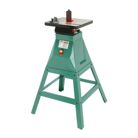
Grizzly G1071 User manual

VERTICAL SPINDLE SANDER
MODEL G1071
INSTRUCTION MANUAL
COPYRIGHT © 1995 BY GRIZZLY INDUSTRIAL, INC. REG # TX 4 060 296
WARNING: NO PORTION OF THIS MANUAL MAY BE REPRODUCED IN ANY SHAPE
OR FORM WITHOUT THE WRITTEN APPROVAL OF GRIZZLY INDUSTRIAL, INC.
REVISED FEBRUARY, 1999. PRINTED IN U.S.A.

-2-

- 1 -
G1071 Oscillating Spindle Sander
TABLE OF CONTENTS PAGE
I. INTRODUCTION....................................................................................................................2
II. SAFETY RULES FOR ALL TOOLS..................................................................................3-4
III. ELECTRICAL SERVICE REQUIREMENTS ........................................................................5
A. CIRCUIT LOADING ..................................................................................................5
B. GROUNDING ............................................................................................................5
C. GENERAL INFORMATION........................................................................................5
IV. SITE PLANNING ..................................................................................................................6
A. FLOOR LOAD ............................................................................................................6
B. WORKING CLEARANCES ........................................................................................6
C. LIGHTING AND OUTLETS........................................................................................6
V. UNPACKING ........................................................................................................................6
VI. PIECE INVENTORY..............................................................................................................7
VII. CLEAN UP BEFORE ASSEMBLY ......................................................................................7
VIII. ASSEMBLY ..........................................................................................................................8
A. SPINDLES..................................................................................................................8
B. LUBRICATION ..........................................................................................................8
C. INSERTS....................................................................................................................9
D. SANDING SLEEVES ................................................................................................9
E. DUST COLLECTION ................................................................................................9
IX. TABLE ANGLE ..................................................................................................................10
X. SANDER SAFETY ..............................................................................................................11
XI. OPERATIONS ....................................................................................................................12
XII. MAINTENANCE ..................................................................................................................13
A. LUBRICATION ........................................................................................................13
B. SANDING SLEEVE MAINTENANCE ......................................................................13
XIII. TROUBLESHOOTING ........................................................................................................14
XIV. CLOSURE............................................................................................................................15
MACHINE DATA..................................................................................................................16
MAIN BODY PARTS DIAGRAM..........................................................................................18
SPINDLE PARTS DIAGRAM ..............................................................................................19
PARTS LIST ..................................................................................................................20-21
XV. WARRANTY AND RETURNS ............................................................................................22

- 2 - G1071 Oscillating Spindle Sander
We are proud to offer the Model G1071
Oscillating Spindle Sander. The Model G1071 is
part of a growing Grizzly family of fine wood-
working machinery.
When used according to the guidelines set forth
in this manual, you can expect years of trouble-
free, enjoyable operation and proof of Grizzly’s
commitment to customer satisfaction.
The Model G1071 is intended for use in a home
or small professional shop. This spindle sander
features a 1 HP, 110V/220V single phase motor
which rotates at 1,720 RPM with 72 oscillations
per minute. At a net working weight of 284 lbs.,
the Model G1071 is one of the heaviest and most
powerful vertical spindle sanders on the market.
All running parts utilize shielded ball bearings,
which require no lubrication for the life of the
bearings.
We are also pleased to provide this instructional
manual with the Model G1071 Oscillating Spindle
Sander. This manual was written to guide you
through assembly, review safety considerations
and cover general operating procedures.
If you have any criticisms that you feel we should
address in our next printing, please write to us at
the Bellingham, WA address at the end of this
section.
Most important, we stand behind our machines.
We have excellent regional service departments
at your disposal should the need arise. If you
have any service questions or parts requests,
please call or write to us at the location listed
below.
Grizzly Industrial, Inc.
1203 Lycoming Mall Circle
Muncy, PA 17756
Phone: (570) 546-9663
Fax: (800) 438-5901
E-Mail: [email protected]
Web Site: http://www.grizzly.com
To comment on this manual write to:
Grizzly Industrial, Inc.
C/OTechnical Documentation
P.O. Box 2069
Bellingham, WA 98227-2069
To operate this or any power tool safely and effi-
ciently, it is essential to become as familiar with it
as possible. The time you invest before you begin
to use your Model G1071 will be time well spent.
DO NOT operate this machine until you are
completely familiar with the contents of this
manual. Serious personal injury may occur
if used without proper training.
I. INTRODUCTION

- 3 -
G1071 Oscillating Spindle Sander
II. SAFETY RULES FOR ALL TOOLS
The Model G1071 is inherently dangerous. Using the tool with respect and caution will
lessen the possibility of mechanical damage or operator injury. If normal safety precau-
tions are overlooked or ignored, serious personal injury may occur.
This machine is specifically designed for wood sanding operations. Modifications or
improper use of this tool can result in damage to the machine and possible operator injury,
and will void all warranties. If you are confused about any aspect of this machine, DO NOT
use it until you have resolved any questions you might have. The following are important
safety rules for all tools:
1. KNOW YOUR POWER TOOL. Read
the owner’s manual carefully. Learn the
tool’s applications and limitations, as
well as its hazards.
2. KEEP ALL GUARDS IN PLACE and in
working order.
3. GROUND ALL TOOLS. If an adapter is
used to accommodate a two-prong
receptacle, the adapter plug must be
attached to a known ground. Never
remove the grounding prong.
4. REMOVE ADJUSTING KEYS AND
WRENCHES. Make it a habit to check
that keys and adjusting wrenches are
removed from the machine before turn-
ing it on.
5. KEEP WORK AREA CLEAN.
Cluttered areas and benches invite
accidents.
6. AVOID DANGEROUS ENVIRON-
MENTS. Do not use power tools in
damp or wet locations or expose them
to rain. Keep your work area well light-
ed.
7. KEEP CHILDREN AND VISITORS
AWAY. All children and visitors should
be kept a safe distance away from your
work area. Serious injuries could occur.
8. MAKE WORKSHOP CHILD-PROOF
with padlocks, master switches, or by
removing starter keys.
9. DO NOT FORCE TOOL. Tools work
better and more safely when they are
allowed to work at their own speed.
10. USE THE RIGHT TOOL. Do not use a
tool or an attachment to do a job that it
was not intended to perform.
11. WEAR PROPER APPAREL. Do not
wear loose clothing, gloves, neckties, or
jewelry that might get caught in moving
parts. Non-slip footwear is also recom-
mended. Wear a hat or other protective
head wear if your hair is long.
12. USE SAFETY GLASSES AND EAR
PROTECTION. Also use a dust mask if
the sanding operation is dusty.
13. SECURE YOUR WORK. Use clamps or
a fixture to hold your work. It is safer
than using your hands and frees up
both hands for operating the tool.
14. DO NOT OVERREACH. Keep proper
footing and balance at all times.
15. MAINTAIN TOOLS IN TOP CONDI-
TION. Keep tools sharp and clean for
best and safest performance. Follow
instructions for lubricating and changing
accessories.

- 4 - G1071 Oscillating Spindle Sander
II. SAFETY RULES FOR ALL TOOLS - CONT’D
16. DISCONNECT TOOLS FROM
POWER before servicing and when
changing accessories such as sanding
sleeves.
17. USE ONLY RECOMMENDED
ACCESSORIES. Consult the current
catalog for recommended accessories.
Using improper accessories may be
hazardous.
18. AVOID ACCIDENTAL STARTING.
Make sure the switch is in the “OFF”
position before plugging in the cord.
19. NEVER STAND OR LEAN ON TOOL.
Serious injury could occur if the tool is
tipped or if the spindle is accidentally
contacted while running.
20. CHECK DAMAGED PARTS. Before
further use of the tool, any part or guard
that is damaged should be promptly
repaired or replaced. Do not operate
the machine until you are certain that it
is in perfect running condition. Failure
to follow this precaution could result in
further mechanical damage and opera-
tor injury.
21. ALWAYS FEED YOUR WORK
AGAINST THE DIRECTION OF SPIN-
DLE TRAVEL. Workpieces fed in the
same direction as the spindle travel
could be forced out of your control.
22. NEVER LEAVE THE TOOL RUNNING
UNATTENDED - TURN POWER OFF.
Do not leave the tool unattended until it
comes to a full stop.
23. DO NOT OPERATE THE TOOL
UNDER THE INFLUENCE OF
DRUGS, ALCOHOL, OR ANY MED-
ICATION. Never operate machinery
when overly fatigued.
24. DO NOT WORK IN HASTE or operate
machine if you are mentally or physi-
cally fatigued.
25. IF THERE IS SOMETHING YOU DO
NOT KNOW OR UNDERSTAND, DO
NOT OPERATE MACHINE! Ask for
help first. Confusion can be dangerous.
26. BAD HABITS ARE DANGEROUS.
Review all safety procedures often.
These safety rules, while expansive,
may not cover every situation in a wood-
shop. Please consider your unique con-
ditions when setting up and using your
sander.

- 5 -
G1071 Oscillating Spindle Sander
III. ELECTRICAL SERVICE REQUIREMENTS
C. GENERAL INFORMATION
If converting to 220V, it will be necessary to
connect a plug that matches your 220V recep-
tacle. If you will be installing a new receptacle
and plug, we recommend either of the follow-
ing styles.
EXTENSION CORDS: If used, extension
cords must be rated hard service – grade S –
or better. Conductor size must be 12 AWG for
cords up to 50 feet in length. Your extension
cord must also contain a ground wire and plug
pin. Repair or replace extension cords if they
become damaged.
A. CIRCUIT LOADING
The G1071 motor will safely draw about 14
amps at 110V (7A @ 220V) under load. If you
operate the sander on any circuit that is
already close to its capacity, it might blow a
fuse or trip a circuit breaker. However, if an
unusual load does not exist, and power fail-
ure still occurs, have the circuit inspected by
a qualified electrician.
CIRCUIT BREAKERS/FUSES: A 15 amp cir-
cuit breaker or fuse should be used for a
110V undedicated circuit. A 10 amp circuit
breaker or fuse should be used for a 220V
undedicated circuit. The general rule is to use
the lightest breaker or fuse that will hold
under regular loads. Circuit breakers or fuses
that are rated higher may not adequately pro-
tect the motor.
B. GROUNDING
This machine must be electrically ground-
ed. We have furnished the sander with a cord
suitable for use with a grounded, domestic
110V circuit.
220V/240V
20A
NEMA 6-20
220V/240V
20A
NEMA L6-20
Standard Locking
Figure 1 220V plug/receptacles.
In this section we have covered some basic
electrical requirements for the safe opera-
tion of your sander. Keep in mind that these
requirements are not necessarily compre-
hensive. Further, you must be sure that your
particular electrical configuration complies
with local and state codes. The best way to
ensure compliance is to check with your
local municipality or licensed electrician.
Please verify that any circuit you intend to
use is actually grounded. If the circuit is not
grounded, it will be necessary to run a sep-
arate 12 AWG copper grounding wire from
the machine frame to a grounding terminal
in your electric service panel.
If you are not sure about wiring your
sander, don’t take chances: consult the
service department or an electrician.
The Model G1071 has a 1 HP motor that
operates at 110V/220V. It has been pre-wired
for 110V, single phase operation. Please con-
sult the wiring diagram for information about
conversion to 220V.

- 6 - G1071 Oscillating Spindle Sander
The sander is shipped from the factory in a
carefully-packed carton. If you find the
machine to be damaged after you’ve signed
for delivery and the truck and driver are
already gone, you will need to file a freight
claim with the carrier. Save the containers and
all packing materials for inspection by the car-
rier or its agent. Without the packing materi-
als, filing a freight claim can be difficult. If you
need advice regarding this situation, please
contact us immediately.
When you are completely satisfied with the
condition of your shipment, you should inven-
tory its parts.
V. UNPACKING
A. FLOOR LOAD
Your G1071 Sander represents a large weight
load in a small footprint. Most commercial
floors are suitable for the Model G1071. Some
residential floors may require additional build
up to support both machine and operator.
B. WORKING CLEARANCES
Working clearances can be thought of as the
distances between machines and obstacles
that allow safe operation of every machine
without limitation. Consider existing and antic-
ipated machine needs, size of material to be
processed through each machine, and space
for auxiliary stands and/or work tables. Also
consider the relative position of each machine
to one another for efficient material handling.
Be sure to allow yourself sufficient room to
safely run your machines IN ANY FORESEE-
ABLE OPERATION.
C. LIGHTING AND OUTLETS
Lighting should be bright enough to eliminate
shadows and prevent eye strain. Electrical cir-
cuits should be dedicated or large enough to
handle combined motor amperage loads.
Outlets should be located near each machine
so power or extension cords do not obstruct
high-traffic areas. Be sure to observe local
electrical codes for proper installation of new
lighting, outlets, or circuits.
IV. SITE PLANNING
The G1071 is a very heavy machine (300
lbs. shipping weight). DO NOT over-
exert yourself while unpacking or mov-
ing your machine – get assistance. In
the event that your sander must be
moved up or down a flight of stairs, be
sure that the stairs are capable of sup-
porting the combined weight of the
machine and the people moving it.

- 7 -
G1071 Oscillating Spindle Sander
Take a quick inventory of the parts and put
them aside for later assembly.
Since the majority of the spindle sander is
pre-assembled at the factory, there aren’t a lot
of items to inventory. You should have the fol-
lowing items:
• Spindle Sander Unit
• Sanding Spindles (10)
• Table Inserts (3)
• Spindle Wrenches (2)
• Allen®Wrench (1)
VI. PIECE INVENTORY
The table is coated with a waxy oil to protect it
from corrosion during shipment. Remove the
protective coating with common paint thinner
(mineral spirits) and paper towels.
VII. CLEAN UP
Follow the safety rules listed below
when working with solvents.
1. Read and follow all directions and
warnings on the solvent label.
2. Work only in a well ventilated area.
3. Do not work near any type of open
flame (e.g., pilot lights, kerosene
heaters, wood stoves and so on).
4. DO NOT smoke while working with
flammable material.
5. Paper towels from the cleaning
process are extremely combustible.
Dispose of waste towels so they do
not create a fire hazard.
Do not use gasoline or other petroleum-
based solvents because of their extremely
low flash points. Do not use acetone or
chlorine-based solvents – if you happen to
splash some onto painted surfaces, you’ll
damage the sander’s finish.
All die-cut metal parts have a sharp edge
(called “flashing”) on them after they are
formed. This is removed at the factory.
Sometimes, though, a bit of flashing
might escape inspection. Please exam-
ine the edges of all die-cut metal parts
before handling them.

- 8 - G1071 Oscillating Spindle Sander
The Model G1071 comes equipped with a
wrench for spindle removal. It should be kept
close to the machine for easy access. The
Model G1071 features two spindle racks
which hold spindles in a handy location when
they are not in use. The spindles are held in
place on the racks by hex nuts.
To install sanding spindles on the Model
G1071:
1. Pick out the appropriate spindle and
remove it from the rack.
2. Drop the threaded end of the spindle into
the spindle hole. Make sure the hole
and the shaft are lightly greased.
3. Screw the spindle in by hand. Sanding
action will further tighten the spindle so it
is unnecessary to over tighten. Figure 2.
4. The spindle is now mounted.
To remove the sanding spindle:
1. Use your spindle wrench provided with
the machine to hold the jam nuts above
the spindle cover while loosening the
spindle retainer nut with another wrench.
2. Unscrew the sanding spindle and return it
to the storage rack.
Assembly of the G1071 is straightforward.
We have organized the assembly process
into steps. Please follow them in sequence.
Review the parts diagrams and lists frequent-
ly to become familiar with all of the parts
before you begin.
ORDER OF ASSEMBLY
A. Spindles
B. Lubrication
C. Table Inserts
D. Sanding Sleeves
E. Dust Collection
TOOLS REQUIRED: Common hand tools
are necessary to assemble this machine. In
addition to the tools provided with your
sander, you will need a large Phillips®head
screwdriver and a set of Allen®wrenches.
VIII. ASSEMBLY
Figure 2 Closeup of a mounted spindle.
Spindle Cover
Jam Nuts
Spindle Retainer Nut
A. SPINDLES
Spindle size should be based on needs of the
project. Straight or gently curved surfaces will
be best suited to the largest of the spindles.
Tighter, more-intricate workpieces will require
the smaller spindles. Avoid the temptation to
leave the same spindle on until its sanding
sleeve wears out. You’ll get much more life
from each of your sanding spindles if they are
used only for specific jobs.
B. LUBRICATION
Check the gear oil level using the dipstick
which is located at the front of the machine
just below the table. See Figure 7. This oil
level should indicate full before the intitial run
of the machine. See Maintenance Section for
more details on lubrication of the Spindle
Sander.

- 9 -
G1071 Oscillating Spindle Sander
2. Remove the sleeve from the spindle. If
you have worn the sleeve out on one end,
you can extend the life of the sleeve by
flipping it over and refitting it on the spin-
dle. If the entire sleeve is worn out,
replace with a new sleeve of the correct
diameter.
3. Re-tighten the hex nut at the top of the
spindle (or setscrews at the base) and
begin using again.
E. DUST COLLECTION
The Model G1071 is capable of creating a
large amount of dust while in use. If you have
a dust collection system in your shop, you
should create a duct to service the spindle
sander. The exhaust hood is designed to
accommodate 4" flexible collection hose. Note
the location of the Dust Port in Figure 3.
If a dust collection system is not available, you
might consider purchasing adapters that will
enable you to use your shop vacuum to work
as a portable dust collection tool. The Grizzly
catalog provides a wide variety of dust collec-
tors and dust collection accessories. See the
latest issue of the Grizzly catalog for more
information.
VIII. ASSEMBLY - CONT’D
C. TABLE INSERTS
The three inserts included with the Model
G1071 are sized to provide free sanding spin-
dle movement while minimizing the gap
between the abrasive surface and the table
top. The holes in the inserts are shaped to
allow the sanding spindles to rotate freely
even when the table is angled to its maximum
45° pitch.
Place the insert with the smallest diameter
which allows free movement of the spindle
over the top of the spindle and lower it into the
hole in the table top. The insert is fitted with
pins which only allow it to fit securely in one
position on the table. That position allows the
table to tilt without impeding the movement of
the spindle.
Each insert is fitted with setscrews which
enable you to adjust the insert’s height. Use
those setscrews to adjust the insert to match
the height of the tabletop. Smooth movement
of your workpiece is essential for proper
sander operation. Make sure your inserts are
aligned as closely to the table as possible.
D. SANDING SLEEVES
Grizzly offers sleeves in 60, 80, 100, 120 and
150 grit. Please refer to the Grizzly catalog
for ordering information.
To replace the sleeves:
1. Loosen the hex nut at the top of the
sanding spindle (spindles 5/8" and small-
er have setscrews at their bases that
secure the sleeves to the spindle).

- 10 - G1071 Oscillating Spindle Sander
The Angle Adjustment Levers enable the
table top to be tilted up to 45° to the front and
20° to the rear. Figure 3. Both levers must be
released to allow the table to tilt. The levers
are located under the table on both the left
and right sides of the sander. The angle indi-
cator shows the degree of pitch.
To calibrate the angle indicator:
1. Use a quality machinist’s square and
bring the table perpendicular (90°) to the
spindle. Move the square around the
sanding spindle to ensure that the table
is square in all directions. Figure 4.
2. Lock the levers down when your table is
square to the sanding spindle. You can
now calibrate the angle indicator arrow
(shown in Figure 3) by loosening its
retaining screw and turning the arrow
until it points directly to “zero” on the
angle guide.
There is a positive stop bolt (#54) that, when
adjusted correctly, allows you to return the
table square to the spindle with little effort.
The positive stop bolt is a long bolt located
below the table.
To adjust the positive stop bolt:
1. Loosen the jam nut on the positive stop
bolt.
2. With the table square to the spindle and
tightened securely, adjust the positive
stop bolt so it just touches the table.
3. Re-tighten the jam nut.
4. If angling the table over the dust port, first
loosen the jam nut and then remove the
stop bolt completely. You can then tilt the
table back to 20°. Don’t forget to re-cali-
brate the stop bolt when you put it back
in.
Figure 3 Location of angle adjustment and dust
port.
Figure 4 Squaring the table to the spindle.
IX. TABLE ANGLE
Angle Indicator Arrow
Angle Adjustment Lever
Dust Port

- 11 -
G1071 Oscillating Spindle Sander
X. SANDER SAFETY
9. BE SURE TO OBSERVE ELECTRI-
CAL REQUIREMENTS SUCH AS
FUSE SIZING, WIRE SIZING, AND
GROUNDING.
10. ENSURE THAT THE SWITCH IS IN
THE OFF POSITION BEFORE PLUG-
GING THE MACHINE INTO ITS
POWER SOURCE.
11. DO NOT stand directly in line with sand-
ing accessories when turning the
machine on.
12. DO NOT force the workpiece against
the spindle during operation. Firmly
grasp the workpiece in both hands and
ease it against the spindle using light
pressure.
13. DO NOT wear loose clothing while
operating this machine. Roll up sleeves
or button sleeves at the cuff.
14. DO NOT place hands near, or in contact
with sanding sleeve during operation.
15. PERFORM MACHINE INSPECTIONS
and maintenance service promptly
when called for.
16. ANY PROBLEM that is concerned at all
with any moving parts or accessories
must be investigated and corrected with
the power disconnected, and after
everything has come to a complete
stop.
It cannot be assumed that additional safety
measures are not needed under particular or
exceptional circumstances or conditions.
Consider safety at all times.
1. MAINTAIN A SECURE GRIP ON THE
WORKPIECE. The spindle rotates at
more than 1700 R.P.M. If control is lost,
the workpiece could be shot from the
machine at extreme speed.
2. CREATE A SAFETY ZONE AROUND
THE SANDING SURFACE. If you can't
control your workpiece with your hands
at least 6" away from the sanding
sleeve, you should create a jig or other
device to hold the workpiece safely.
3. DON’T OPERATE THE SPINDLE
SANDER if the proper insert is not in
place.
4. REPLACE SLEEVES WHEN WORN
OR DAMAGED. A torn or damaged
sleeve could be unexpectedly expelled
from the machine if not replaced.
5. KEEP YOUR WORKPIECE SOLIDLY
ON THE SANDER TABLE. A well-
secured workpiece is less likely to lose
control during sanding operations.
6. INSPECT MATERIALS FOR
DEFECTS. Knots and splinters can
shoot from the machine with great
force. Make sure defective materials
are not used on the spindle sander.
Foreign objects such as nails and sta-
ples should also be removed before
sanding.
7. TURN OFF THE SANDER WHEN NOT
IN USE. Never leave a machine run-
ning unattended.
8. ALWAYS wear eye protection and a
respirator.
When the guidelines illustrated in this manual
are followed, the Model G1071 is a safe and
enjoyable tool to use, even for the novice
woodworker. Please follow these specific
safety rules before beginning to use your
machine.

- 12 - G1071 Oscillating Spindle Sander
XI. OPERATIONS
BEFORE STARTING YOUR SANDER FOR
THE FIRST TIME, CHECK OIL LEVEL AND
GREASE POINTS. See Maintenance
Section for more information. Check at least
monthly thereafter.
Also before starting the sander, be sure you
have followed all the guidelines for set up. If
everything checks out, push the “ON” button
and let the machine run. After a few moments,
turn the machine off and use a piece of scrap
wood to get a feel for the machine. As we
noted in the sander safety guidelines, you
should be sure that any wood you use is free
of defects and foreign objects.
The Model G1071 is designed to give clean
finished edges to your work, so when pre-cut-
ting with your jigsaw or bandsaw, make a
habit of cutting about 1/16" outside the edges of
your finished workpiece. Mark a clean line
with a pencil or scribe along the desired out-
side edge of your workpiece, or in this case,
your test piece.
When you’ve marked your material, turn the
Model G1071 on again. Let it reach its work-
ing speed and slide the test piece against the
sanding surface. The sander requires little
pressure between the spindle and workpiece.
Move your test piece against the rotation of
the sanding spindle. To achieve the best
results, remove excess material in several
passes. Your results will be more even and
you’ll have less chance of accidentally remov-
ing too much material or burning your work.
Using this method will also decrease wear on
your sanding sleeves.
Now, try bevel sanding. Turn off the machine
and tilt the table to the angle of bevel you
desire. Spin the sanding spindle by hand to
ensure there is free movement. When bevel-
ing, always place your scribe marks at the
outside (longest) edge of your bevel, so you
can see the marks from above. After restart-
ing the machine, gently press the test piece
against the sanding spindle and take several
passes until your scribe lines are reached.
Placing a 1" or thicker false table over the
sander’s table will offer several advantages. It
will raise the working surface up and make
beveled sanding with the larger spindles eas-
ier. It will bring your working surface closer to
the spindle for better control of smaller work-
pieces. It will allow you to more fully utilize the
entire length of your sanding sleeves, espe-
cially when working with thin workpieces. The
false table can be moved around on the
sander’s table and secured by C-clamps.
Figure 6 Angled or bevel sanding (45°).
Figure 5 Flat sanding.

- 13 -
G1071 Oscillating Spindle Sander
XII. MAINTENANCE
Your Model G1071 Spindle Sander requires
very little maintenance. Cleaning will increase
the machine’s durability and efficiency by
removing grime which can gum up moving
parts. If you find that the machine sands less
efficiently than usual, inspect the sanding
sleeves and clean with a gum rubber belt
cleaner (available in the Grizzly catalog) or
replace them as needed. An occasional appli-
cation of good quality automotive paste wax
(one which does not contain silicone or other
synthetics) will keep the sander table and
other bare metal parts from rusting and pit-
ting.
A. LUBRICATION
Bearings:
The Model G1071 features factory-sealed
bearings. A sealed bearing requires no lubri-
cation during its lifetime.
Should a bearing fail, your spindle sander will
probably develop a noticeable rumble, which
will increase when the machine is put under
load. Bearings must be replaced when this
occurs. Bearings are standard sizes and can
be replaced through Grizzly.
Gear Oil:
Gear oil should be changed yearly (if sander
is used daily) with a high-quality 90 Wt. gear
oil. The oil cap w/dipstick is located at the
front of the machine, just below the table.
Figure 7. The drain plug is at the base of the
gear housing and is accessed through the
door on the cabinet. The sander takes approx.
2.8 quarts.
In addition to yearly replacement, the oil level
should be checked at least monthly and oil
added when indicated by the dipstick.
The sander is equipped with a breather valve
to allow heated vapors to escape from the oil
housing. DO NOT TRY TO ADJUST THE
BREATHER VALVE WITHOUT FIRST CON-
SULTING THE SERVICE DEPARTMENT!
Trunnions:
The trunnions should be lubricated with medi-
um grease as needed to make table adjust-
ment easier.
B. SANDING SLEEVE
MAINTENANCE
Sanding sleeves should be inspected periodi-
cally for wear or damage. Damaged sleeves
should be replaced before further use. Do not
allow the rubber portion of the spindle to come
in contact with workpieces during operation.
Damage to the rubber will occur.
Figure 7 Locations of the oil cap and breather
valve. The spindle grease fitting is on the other
side of the spindle from these parts.
Oil Cap w/Dipstick Breather Valve
Spindle Cover

G1071 Oscillating Spindle Sander
SYMPTOM
Motor will not start.
Motor will not start;
fuses or circuit
breakers blow.
Motor fails to devel-
op full power (power
output of motor
decreases rapidly
with decrease in
voltage at motor ter-
minals).
Motor overheats.
Motor stalls (result-
ing in blown fuses or
tripped circuit).
Machine slows
when operating.
Spindle Collar rubs
the edge of the table
when tilted to 45°.
Sanding sleeve
slips.
Sanding sleeve
burns the wood.
XIII. TROUBLESHOOTING
POSSIBLE CAUSE
1. Low or no voltage.
2. Open circuit in motor or
loose connections.
1. Short circuit in line cord
or plug.
2. Short circuit in motor or
loose connections.
3. Incorrect fuses or circuit
breakers in power line.
1. Power line overloaded
with lights, appliances,
and other motors.
2. Undersized wires or cir-
cuits too long.
3. General overloading of
power company facili-
ties.
1. Motor overloaded.
2. Air circulation through
the motor restricted.
1. Short circuit in motor or
loose connections.
2. Low voltage.
3. Incorrect fuses or circuit
breakers in power line.
4. Motor overloaded.
Applying too much
pressure to workpiece.
Table slightly out of
place.
Sleeve loose on spin-
dle.
Worn out sleeve.
CORRECTIVE ACTION
1. Check power line for proper voltage.
2. Inspect all lead connections on motor for
loose or open connections.
1. Inspect cord or plug for damaged insula-
tion and shorted wires.
2. Inspect all connections on motor for loose
or shorted terminals or worn insulation.
3. Install correct fuses or circuit breakers.
1. Reduce load on power line.
2. Increase wire sizes or reduce length of
wire.
3. Request a power check from the power
company.
1. Reduce load on motor.
2. Clean out motor to provide normal air cir-
culation.
1. Inspect connections on motor for loose or
shorted terminals or worn insulation.
2Correct the low voltage conditions.
3. Install correct fuses or circuit breakers.
4. Reduce load on motor.
Feed workpiece slower.
Loosen the 4 bolts that mount the tables
to the trunnions. Shift the table slightly to
eliminate contact.
Tighten upper sanding sleeve nut.
Replace sleeve.
Turn switch off and disconnect from power source before troubleshooting the machine.
- 14 -

-15-
The following pages contain general machine
data, parts diagram, parts list and Warranty/Return
information for your Model G1071 Oscillating
Spindle Sander.
If you need parts or help in assembling your
machine, or if you need operational information,
we encourage you to call the appropriate region-
al Service Department. Our trained service tech-
nicians will be glad to help you.
If you have comments dealing specifically with
this manual, please write to our Bellingham,
Washington location using the address in the
Introduction. The specifications, drawings, and
photographs illustrated in this manual represent
the Model G1071 as supplied when the manual
was prepared. However, due to Grizzly’s policy of
continuous improvement, changes may be made
at any time with no obligation on the part of
Grizzly. Whenever possible, though, we send
manual updates to all owners of a particular tool
or machine. Should you receive one, add the new
information to this manual and keep it for refer-
ence.
We have included some important safety mea-
sures that are essential to this machine’s opera-
tion. While most safety measures are generally
universal, Grizzly reminds you that each work-
shop is different and safety rules should be con-
sidered as they apply to your specific situation.
We recommend you keep a copy of our current
catalog for complete information regarding
Grizzly's warranty and return policy. If you need
additional technical information relating to this
machine, or if you need general assistance or
replacement parts, please contact the appropri-
ate regional Service Department listed in the
introduction.
Additional information sources are necessary to
realize the full potential of this machine. Trade
journals, woodworking magazines, and your local
library are good places to start.
As with all power tools, there is danger
associated with the Model G1071
Oscillating Spindle Sander. Use the tool
with respect and caution to lessen the pos-
sibility of operator injury or mechanical
damage. If normal safety precautions are
overlooked or ignored, serious personal
injury is possible.
The Model G1071 was specifically designed
for spindle sanding operations. If you are
confused about any aspect of this machine,
DO NOT use it until you have answered all
your questions.
XIV. CLOSURE
Do not modify and/or use this OSCILLATING
SPINDLE SANDER for any other purpose
other than those for which it was designed.
Modifications or improper use of this tool
could result in serious personal injury and
property damage and will void the warranty.
G1071 Oscillating Spindle Sander

Customer Service #: (570) 326-3806 • To Order Call: (800) 523-4777 • Fax #: (800) 438-5901
- 16 - G1071 Oscillating Spindle Sander
Design Type...................................................................................................... Floor Model
Overall Dimensions:
Table..........................................................................................................251⁄8" x 251⁄8"
Table Height ..........................................................................................................361⁄4"
Base Size ........................................................................................................16" x 16"
Spindle Sizes ......................................................1⁄4", 3⁄8", 1⁄2", 5⁄8", 3⁄4",1", 11⁄2", 2", 3", 4"
Dust Port.................................................................................................................... 4"
Shipping Weight .............................................................................................. 300 lbs.
Construction:
Stand ......................................................................Stamped Steel- Welded Assembly
Table ................................................................................................ Ground Cast Iron
Motor:
Type......................................................................................................................TEFC
Horsepower ............................................................................................................1 HP
Phase ⁄ Cycle .............................................................................. Single Phase ⁄ 60 Hz
Voltage..................................................................................110/220V -prewired 110V
Amps ......................................................................................................................14⁄7
RPM ......................................................................................................................1720
Bearings........................................................Shielded & Permanently Lubricated Ball
Switch ..............................................................................On/Off Toggle w/Safety Lock
Power Transfer ..........................................................................................Direct Drive
Features:
Stroke Length ..........................................................................................................11⁄2''
Table Opening ........................................................................................................67⁄8''
Table Inserts ................................................................................................................3
Table Tilt ..................................................................................................45° Left ⁄ 20°
Oscillations ..................................................................................................72 ⁄ minute
Specifications, while deemed accurate, are not guaranteed.
GRIZZLY MODEL G1071
OSCILLATING SPINDLE SANDER
MACHINE DATA
SHEET
REVISED 2/99

- 17 -
G1071 Oscillating Spindle Sander
NOTES

- 18 - G1071 Oscillating Spindle Sander
MAIN BODY PARTS DIAGRAM
85
66
67
89
866160
97
35
12
98
121
101
76
100
24101
23
23
22
97
16
99
13 18
19 18
89
89 89
89
90
20
91
17
15
9
8
104
103
69
87
54
114
10
20 21
21
102
93
82
25
95
94
96
68
55
A
A
73
66
5
85
6
80
80
82
65
70
92
82
119 81
82
113
72
75
123
74
62
71
112
107
108
117
11
89 89
14 81
88
7
82 82
82
4
81
82
82 465
2
84
118
83
83 83
3
184
84
Other manuals for G1071
4
Table of contents
Other Grizzly Sander manuals

Grizzly
Grizzly G9980 User manual

Grizzly
Grizzly G1183/G1276 User manual

Grizzly
Grizzly G9983 User manual

Grizzly
Grizzly G0563 User manual

Grizzly
Grizzly G0527 User manual

Grizzly
Grizzly G1014Z User manual

Grizzly
Grizzly H0590 Quick start guide

Grizzly
Grizzly G0472 User manual

Grizzly
Grizzly H3143 Guide

Grizzly
Grizzly T25942 User manual

Grizzly
Grizzly G0487 User manual

Grizzly
Grizzly G0486/G0487 User manual

Grizzly
Grizzly G0538 Quick start guide

Grizzly
Grizzly G1066 User manual

Grizzly
Grizzly H8253 User manual

Grizzly
Grizzly G1071 User manual

Grizzly
Grizzly G0581 User manual

Grizzly
Grizzly G1079R User manual

Grizzly
Grizzly G8749 User manual

Grizzly
Grizzly H7761 Quick start guide