Groen HY-3E User manual

PIMPORTANT INFORMATION PKEEP FOR OPERATOR PIMPORTANT INFORMATION P
Old Model
New Model
OPERATOR MANUAL OM-HY-3E
Part Number 121004 - Rev. B DOMESTIC
MODELS: HY-3E,(2)HY-3E, (3)HY-3E
HyPerSteam™
Atmospheric Convection
Steamer
Self-Contained
Electric Heated
Capacity: 3 Steamer Pans [per cavity]
(12" x 20" x 2½”)
THIS MANUAL MUST BE RETAINED FOR FUTURE REFERENCE. READ,
UNDERSTAND AND FOLLOW THE INSTRUCTIONS AND WARNINGS
CONTAINED IN THIS MANUAL.
FOR YOUR SAFETY
DO NOT STORE OR USE GASOLINE OR OTHER FLAMMABLE VAPORS AND
LIQUIDS IN THE VICINITY OF THIS OR ANY OTHER APPLIANCE.

OM-HY-3E
2
IMPORTANT — READ FIRST — IMPORTANT
WARNING: THE UNIT MUST BE INSTALLED BY PERSONNEL QUALIFIED TO WORK WITH
ELECTRICITY AND PLUMBING. IMPROPER INSTALLATION CAN CAUSE INJURY TO
PERSONNEL AND/OR DAMAGE TO THE EQUIPMENT. THE UNIT MUST BE INSTALLED IN
ACCORDANCE WITH APPLICABLE CODES.
CAUTION: SHIPPING STRAPS ARE UNDER TENSION AND CAN SNAP BACK WHEN CUT.
CAUTION: DO NOT INSTALL THE UNIT IN ANY WAY WHICH WILL BLOCK THE RIGHT OR LEFT SIDE
VENTS, OR WITHIN 12 INCHES OF A HEAT SOURCE SUCH AS A BRAISING PAN, DEEP
FRYER, CHAR BROILER OR KETTLE.
CAUTION: LEVEL THE UNIT FRONT TO BACK, OR PITCH IT SLIGHTLY TO THE REAR, TO AVOID
DRAINAGE PROBLEMS.
WARNING: TO AVOID DAMAGE OR INJURY, FOLLOW THE WIRING DIAGRAM EXACTLY WHEN
CONNECTING A UNIT.
CAUTION: DO NOT USE PLASTIC PIPE. DRAIN MUST BE RATED FOR BOILING WATER.
WARNING: DO NOT CONNECT THE DRAIN DIRECTLY TO A BUILDING DRAIN.
WARNING: BLOCKING THE DRAIN IS HAZARDOUS.
IMPORTANT: Improper drain connection will void warranty.
IMPORTANT: Do not allow any water traps in the line. A trap can cause pressure to build up inside the
cavity during steaming, which will make the door gasket leak.
WARNING: WHEN YOU OPEN THE DOOR, STAY AWAY FROM STEAM COMING OUT OF THE UNIT.
STEAM CAN CAUSE BURNS.
WARNING: BEFORE CLEANING THE OUTSIDE OF THE STEAMER, DISCONNECT THE ELECTRIC
POWER SUPPLY. KEEP WATER AND CLEANING SOLUTIONS OUT OF CONTROLS AND
ELECTRICAL COMPONENTS. NEVER HOSE OR STEAM CLEAN ANY PART OF THE UNIT.
WARNING: ALLOW COOKING CHAMBER TO COOL BEFORE CLEANING.
WARNING: CAREFULLY READ THE WARNINGS AND FOLLOW THE DIRECTIONS ON THE LABEL OF
EACH CLEANING AGENT. USE SAFETY GLASSES AND RUBBER GLOVES AS
RECOMMENDED BY DELIMING AGENT MANUFACTURER.
WARNING: DO NOT MIX DE-LIMING AGENTS (ACID) AND DE-GREASERS (ALKALI).
WARNING: DO NOT PUT HANDS OR TOOLS INTO THE COOKING CHAMBER UNTIL THE FAN HAS
STOPPED TURNING.
WARNING: DO NOT OPERATE THE UNIT UNLESS THE REMOVABLE RIGHT SIDE PANEL HAS BEEN
RETURNED TO ITS PROPER LOCATION.
NOTICE: DO NOT USE A CLEANING OR DE-LIMING AGENT THAT CONTAINS ANY SULFAMIC ACID
OR ANY CHLORIDE, INCLUDING HYDROCHLORIC ACID. IF THE CHLORIDE CONTENT OF
ANY PRODUCT IS UNCLEAR, CONSULT THE MANUFACTURER.
NOTICE: DO NOT USE ANY DE-GREASER THAT CONTAINS POTASSIUM HYDROXIDE OR SODIUM
HYDROXIDE OR THAT IS ALKALINE.
WARNING: USE OF ANY REPLACEMENT PARTS OTHER THAN THOSE SUPPLIED BY GROEN OR
THEIR AUTHORIZED DISTRIBUTOR VOIDS ALL WARRANTIES AND CAN RESULT IN
BODILY INJURY TO THE OPERATOR AND DAMAGE THE EQUIPMENT. SERVICE BY
OTHER THAN FACTORY-AUTHORIZED PERSONNEL WILL VOID ALL WARRANTIES.
WARNING: HIGH VOLTAGE EXISTS INSIDE CONTROL COMPARTMENTS. DISCONNECT FROM
BRANCH BEFORE SERVICING. FAILURE TO DO SO CAN RESULT IN SERIOUS INJURY OR
DEATH.

OM-HY-3E
3
Table of Contents
OPERATOR WARNINGS .................................................................... 2
REFERENCES ............................................................................. 3
EQUIPMENT DESCRIPTION ................................................................. 4
INSPECTION AND UNPACKING .............................................................. 4
WATER CONDITIONING/REQUIREMENTS ..................................................... 4
INSTALLATION AND START-UP INSTRUCTIONS ................................................ 6
OPERATING INSTRUCTIONS ............................................................... 10
CLEANING ............................................................................... 12
MAINTENANCE AND TROUBLESHOOTING .................................................... 14
PARTS LIST .............................................................................. 15
SCHEMATICS [New Models] ................................................................. 18
SCHEMATICS [Old Models] .................................................................. 19
SERVICE LOG ............................................................................ 22
WARRANTY PROTECTION ................................................................. 23
References
UNDERWRITERS LABORATORIES, INC.
333 Pfingsten Road
Northbrook, Illinois 60062
KLENZADE SALES CENTER
ECOLAB, Inc.
370 Wabasha
St. Paul, Minnesota 55102
800 328-3663 or 612 293-2233
NATIONAL FIRE PROTECTION
ASSOCIATION
60 Battery March Park
Quincy, Massachusetts 02269
NFPA/70 The National Electrical Code
NATIONAL SANITATION FOUNDATION
3475 Plymouth Road
Ann Arbor, Michigan 48106

OM-HY-3E
4
The new model can be identified by its unique
control panel, and fewer side panel louvers.
The HY-3E steamer holds three standard 12"x
20"x 2-½" deep pans [old model shown].
Equipment Description
Your Groen HY-3E HyPerSteam Convection
Steamer is designed to give years of service. It has
a stainless steel cavity (cooking chamber) which is
served by an independent atmospheric steam
generator which is electrically-heated. A powerful
blower circulates the steam in the cavity to increase
heating efficiency.
The cavity holds up to three steam table pans (12" x
20" x 2½" deep). A 16 gauge stainless steel case
encloses the cavity, the steam generator and the
control compartment that houses electrical
components. Door hinges are reversible (the door
may be set to open from the left or right). Operating
Controls are on the front panel.
Newer model HY-3E steamers (manufactured since
February, 1999) are equipped with fully electronic
controls and a button-activated, pre-programmed
CLEAN cycle. These units are readily identified by
their unique control panels. The On-Off switch on
older models has been replaced by touch pad
controls, and the distinctive symbol for steam is
integrated into the panel. The new models also have
fewer panel louvers on the right side.
From the rear the newer unit is distinguished by the
addition of a “fuse box” which allows the operator to
change fuses without removing panels.
The drain system on all models includes a spray
condenser, which helps keep steam from escaping
from the chamber and cools drain water.
Inspection and Unpacking
The HY3-E will be delivered completely assembled in
a heavy shipping carton attached to a skid. On
receipt, inspect the carton carefully for exterior
damage.
CAUTION
SHIPPING STRAPS ARE UNDER TENSION AND
CAN SNAP BACK WHEN CUT.
Carefully cut the straps around the carton and detach
the sides of the carton from the skid. Pull the carton
up off the unit. Be careful to avoid personal injury or
equipment damage from staples which might be left in
the carton walls.
CAUTION
THIS UNIT WEIGHS 180 POUNDS (82 KG). YOU
SHOULD GET HELP AS NEEDED TO LIFT THIS
WEIGHT SAFELY.
Write down the model number, serial number and
installation date. Keep this information for reference.
Space for these entries is provided at the top of the
Service Log in the back of this manual.
When starting installation, lift the unit straight up off
the skid. Check packing materials to make sure
loose parts such as the condensate drip tray are not
discarded with this material.

OM-HY-3E
5
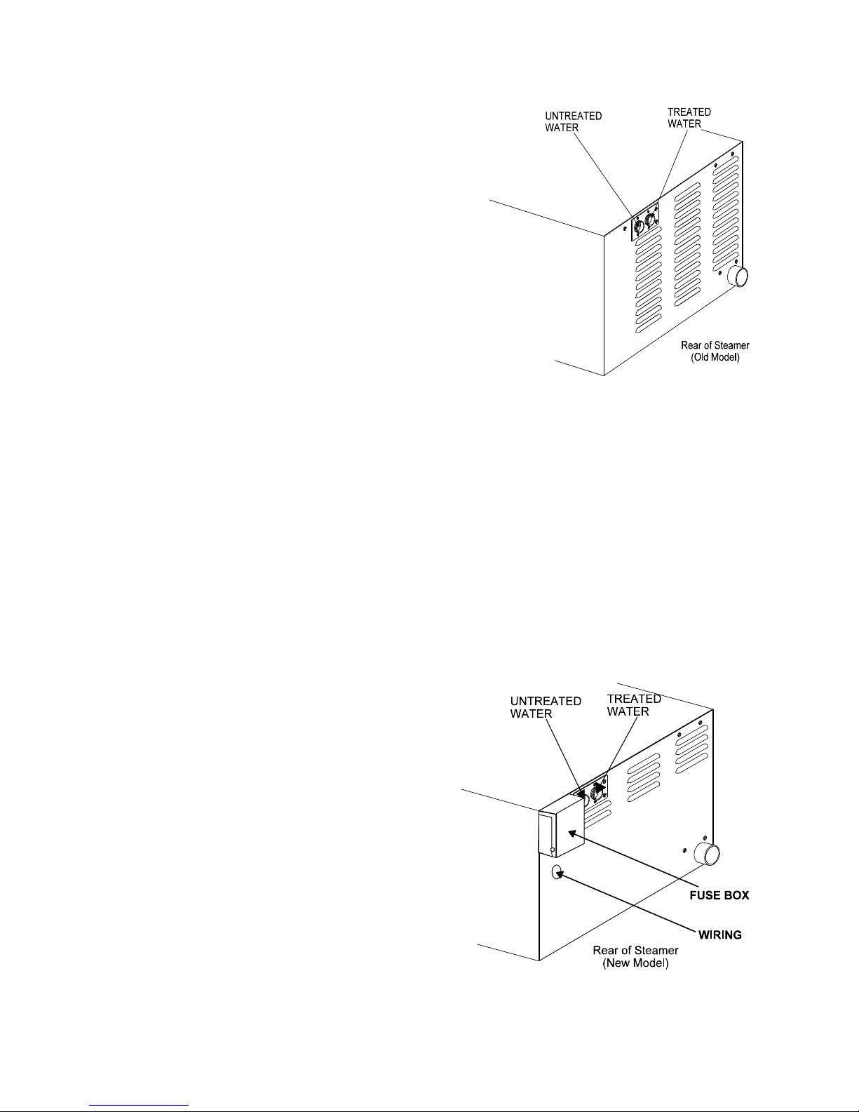
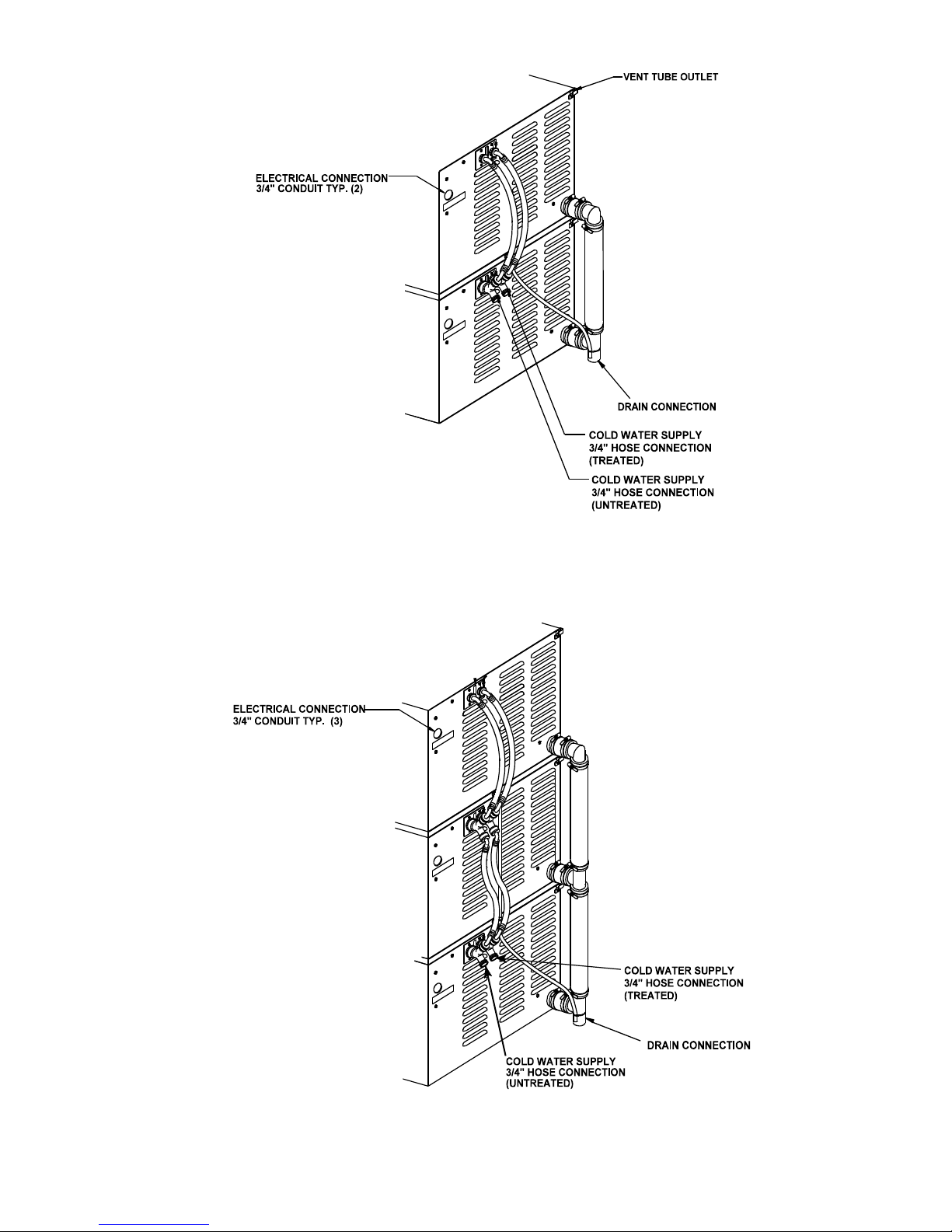
The optional second water connection can reduce
treated water requirements.
New models have a fuse box mounted on
the rear.
Water Conditioning
It is essential to supply the steam generator with water
that will not form scale. Even though the steam
generator is engineered to minimize scale formation,
scale development depends on water hardness and
the number of hours per day you operate the
equipment. In some areas, water is low enough in
mineral content to avoid scale formation. But most
water supplies are full of minerals which form scale. It
is this scale which could lead to an early component
failure.
Your water utility can tell you about the minerals in your
water. For the steam generator's water level sensing
system to function properly, the water must conduct
electrical current. This typically requires it to have a
minimum of 40 parts per million (ppm) total dissolved
solids (TDS) as measured with a Groen Test Kit (P/N
110889). At high TDS concentrations, however,
serious scaling problems may occur. Consult your local
water utility for information and referral regarding
effective water treatment in your area. Please follow
these simple precautions:
1. Do not rely on unproven water treatments
which are sold for scale prevention or scale
removal. The best way to prevent scale is to
supply water with minimum levels of dissolved
solids (but at least 40 ppm TDS).
2. If your water contains scale-forming minerals, as
most water does, use a well-maintained water
softener. Whether an exchangeable softener
cartridge or a regenerating system is chosen, a
regular replacement or regeneration program is
essential.
IMPORTANT: ENSURE ANY WATER TREATMENT
SYSTEM DELIVERS SUFFICIENT WATER VOLUME
AND FLOW RATE.
3. Installing a water meter between the softener and
the steamer will provide an accurate gauge of
water use, and will help determine when to
exchange cartridges or regenerate the softener.
Using a water softener will provide longer
generator life, higher steam capacity, and reduce
maintenance requirements.
4. If you notice a slowdown in steam production, have
the unit checked for scale build-up. Heavy scale
reduces the unit’s ability to boil water, and can
even cause heating elements in the steam
generator to overheat and burn out.
Groen Steamers are also available with an option for
two separate water intakes — one for the steam
generator (soft water), the other for the spray
condenser (untreated water). The steam generator
only uses 14 to 31% of a steamer’s water.
Since softener systems are typically sized by total
GPH (gallons per hour), the second intake could
reduce treatment requirements by up to 80%,
resulting in significant savings.
On the HY-3E, the twin water connections are side
by side on the rear of the unit. When facing the back
of the unit, the treated (softened) water intake is on
the right.

OM-HY-3E
6
Installation and Start-Up
WARNING
THE UNIT MUST BE INSTALLED BY PERSONNEL WHO ARE QUALIFIED TO WORK WITH ELECTRICITY
AND PLUMBING. IMPROPER INSTALLATION CAN CAUSE INJURY TO PERSONNEL AND/OR DAMAGE TO
THE EQUIPMENT. THE UNIT MUST BE INSTALLED IN ACCORDANCE WITH APPLICABLE CODES.
CAUTION
DO NOT INSTALL THE UNIT WITH THE RIGHT OR LEFT SIDE VENTS BLOCKED OR WITHIN 12 INCHES OF
A HEAT SOURCE (SUCH AS A BRAISING PAN, DEEP FRYER, CHAR BROILER OR KETTLE).
TO AVOID DRAINAGE PROBLEMS, LEVEL THE UNIT FRONT TO BACK.
1. Electrical Supply Connection
A. Panel Removal
Open the wiring and control panel by removing
two screws (three on new model) on the right
side panel. Slide the panel forward, and set it
aside.
B. Supply Voltage
The unit must be operated at the rated
nameplate voltage, plus or minus 10 percent.
C. Phase Selection
Refer to heater schematics (Pages 17 thru 20)
for wiring information.
CAUTION
THE UNIT MUST HAVE ASEPARATE GROUND
WIRE FOR SAFE OPERATION.
D. Terminal Block
The terminal block for incoming power is located
at the back of the control compartment. The
ground terminal is located in the wiring
compartment above the terminal block.
Minimum size for the ground wire is 10 AWG.
Supply wire
To determine the type of wire you need for the
power supply, find the operating voltage and
phase on the unit data plate. Refer to the table
below or to the label on the unit’s back for
correct wire size and temperature rating. The
“Electrical Supply Connection” label on back
right side of the unit gives directions for proper
connection of the terminal block jumpers. The
specified wire must be used, or the unit will not
meet Underwriters Laboratories and National
Electric Code requirements. The knockout hole
is sized for a ¾ inch conduit fitting.
WARNING
TO AVOID DAMAGE OR PERSONAL INJURY,
FOLLOW THE ELECTRICAL SCHEMATIC
EXACTLY WHEN CONNECTING THE UNIT..
ELECTRICAL SUPPLY CONNECTIONS
FIELD WIRING TABLE - USE ONLY COPPER WIRE
208 VOLT 240 VOLT 480 VOLT INSULATION
RATING
1 PHASE 3 PHASE 1 PHASE 3 PHASE 3 PHASE
8 AWG 10 AWG 8 AWG 10 AWG 14 AWG THHN (90ºC)

OM-HY-3E
7
E. Branch Circuit Protection
Each HY-3E Steamer should have its own
branch circuit protection. Current and power
demands for the different units are as follows:
VOLTAGE PHASE AMPS MAX. KW
208 1
339
23 8
8
240 1
333
20 8
8
480 3 10 8
2. Water Connection(s)
Install a check valve to prevent back flow in the
incoming cold water line, as required by local
plumbing codes. Water pressure in the line
should be between 30 and 60 PSIG (210 and
420 kPa). If pressure is above 60 PSIG, a
pressure regulator will be needed.
A ¾ inch NH connector (garden hose type) is
used to attach the water supply to the inlet valve.
Minimum water feed line diameter is ½ inch
(13mm). Use a washer in the hose connection.
Do not allow the connection to leak, no matter
how slowly. For the twin water connection
option, treated (softened) water goes to the right
(facing the rear of the unit), and untreated water
to the left. Connections for both are made as
described above.
3. Drain Connection
Level the steamer front to back, or even pitch it
slightly to the rear by adjusting the bullet feet on
the stand or cabinet base.
A 1½ inch (38mm) ID hose may be attached to
the drain pipe (supplied).
WARNING:
DO NOT CONNECT THE DRAIN DIRECTLY TO A
BUILDING DRAIN.BLOCKING THE DRAIN IS
HAZARDOUS.
There must be a free air gap between the end of
the hose and the building drain. The free air gap
should be as close as possible to the unit drain.
There must also be no other elbows or other
restrictions between the unit drain and the two
inch free air gap.
CAUTION
DO NOT USE PLASTIC PIPE. DRAIN MUST BE
RATED FOR VERY HOT WATER.
Install the drain line with a constant downward pitch.
IMPORTANT: Do not allow water traps in the
line. A trap can cause pressure build-up in the
cavity, which may cause the door gasket to leak.
DRAIN LINE INSTALLATION
(OLDER MODELS WITH DRAIN BOX)
OPTION ONE: Use 1½” Drain Kit (P/N 118948) to
nearby floor drain, or from Stainless Elbow (P/N
092272), use “Radiator” Hose (rated at least 212oF),
and an additional clamp (P/N 073259).
OPTION TWO: Using the hose (P/N 073254) and
two hose clamps (P/N 073259), connect 1½” copper
tubing to the floor drain. NOTE: Drain lines must be
pitched downward approximately ¼” per foot.
No water traps are allowed in the drain line.
(NEW MODELS WITHOUT DRAIN BOX)
From the Muller Brass coupling-reducer (P/N W-
1095), connect 1½”“ copper tubing to the floor drain.
For stacked units use Drain Kit P/N 125777.

OM-HY-3E
8
Proper Drain Line Connection — Drain Line
must have a constant downward pitch of at
least ¼” per foot.
Rear view of (2) HY-3E — Note: The drain
hoses, required for installation, are packed
inside one of the steamer cavities.
4. Factory Stacked Units
This section is applicable only if you are installing
factory-mounted stacked units. If you plan to stack
steamers yourself, whether purchasing a new one for
stacking or a kit to stack two units you already own,
you will require OM-HY-3E(S), RETROFIT
SUPPLEMENT (Part Number 121014).
Installing the (2) HY-3E and (3) HY-3E stacked
steamers is similar to installing a single unit. The
steamers are stacked and assembled at the factory
and delivered with the water connections and drain
hoses required for a single point connection.
a. Water Connection
As the drawings on Page 10 show, the same
water supply connection is used. At the water
inlet valve a ¾ inch NH connector (garden hose
type) is used for the water supply. If you have
the second water connection option, there are
two connections to be made. Treated water
(softened) is connected to the right valve fitting
(facing the rear of the unit) and untreated water
to the left valve fitting.
b. Electrical Supply Connection
Separate, individual electrical connections
will be required for each steamer in the stack.
We also strongly recommend that each HY-
3E Steamer have its own branch circuit
protection.
c. Drain Connection
HY-3E steamers must be leveled front to back,
or pitched slightly to the rear by adjusting the
bullet feet on the cabinet or stand base.
A 1½ inch (38.1 mm) ID hose may be attached
to the unit drain. It must be rated for very hot
water.
WARNING
DO NOT CONNECT THE UNIT DRAIN DIRECTLY
TO THE BUILDING DRAIN.
Ensure that there is a free air gap between the end
of the unit drain and the building drain. This gap
should be as close as possible to the unit drain. Do
not allow elbows or restrictions between the unit and
the free air gap.
CAUTION
DO NOT USE PLASTIC PIPE. DRAIN MUST BE
RATED FOR VERY HOT WATER.
Install the line with a constant downward pitch.

OM-HY-3E
9
Figure 2 - Drain and Water Connections for (2) HY-3E with
optional twin hose connections. (Drain Kit P/N 125777)
Figure 3 - Drain and Water Connections for (3) HY-3E with optional twin hose
connections. (Drain Kit P/N 125777).

OM-HY-3E
10
New Models Older Models
Operation
WARNING
ANY POTENTIAL USER OF THE EQUIPMENT SHOULD BE TRAINED IN SAFE AND CORRECT OPERATING
PROCEDURES.
A. Controls
Operator controls are on the front right of the unit.
The control panel on new models has the following
touch pads and indicator lights:
!The ON/OFF touch pad gets the
HyPerSteam ready for use, or shuts it off.
!The READY indicator light shows that the
steam generator is at standby temperature
and the cavity is hot enough to begin
steaming.
!The CLEANING indicator light is lit when the
unit is operating in the cleaning mode.
!The SERVICE indicator light shows when
the water level probes have stopped
working, and need to be cleaned (normally
an indication of lime deposits).
When one probe is not working, the
SERVICE light flashes briefly every few
seconds. When both probes fail, the light
will flash continuously and the beeper will
sound.
!The HI TEMP indicator light comes on when
the steam generator is too hot.
The unit will automatically shut off, and
cannot be turned on again until the steam
generator cools and the HI TEMP indicator
light goes out.
!The TIMING indicator light stays on when
the timer is running.
!The CLEAN touch pad is used to start the
automatic 50 minute cleaning cycle.
Older models have fewer but similar controls and
indicators:
!The ON/OFF switch gets the HyPerSteam
ready for use, or shuts it off.
!The READY indicator light shows that the

OM-HY-3E
11
steam generator is at standby temperature
and the cavity is hot enough to begin
steaming.
!The CLEAN indicator light is lit when the unit
requires de-liming/de-scaling.
The ON button/switch readies the HyPerSteam for
use or shuts it off. The READY light shows the
steam generator is at standby temperature and the
cavity is hot enough to start steaming.
The timer is used in three ways:
1In the OFF position the steam generator
stays at a low boil or “holding” temperature.
2When a cook time is set, the unit steams
until the timer runs down to OFF. At that
time steaming stops, a red light comes on
and a beeper sounds.
3With the timer turned to the ON position, the
unit steams continuously. The green light
stays lit. The steamer will not time down.
B. Operating Procedure
1. Press the ON switch/pad for the steamer. The
steam generator will fill, and heat until the
READY light comes on. (About 10 minutes.)
2. Load food into pans in uniform layers. Pans
should be filled to about the same levels, and
should be even on top.
3. Open the door and slide the pans onto the
supports. If you will only be steaming one pan,
put it in the middle position.
4. Close the door. With the READY indicator lit,
take one of the following steps:
!If you want to steam the food for a certain
length of time, set the timer for that period.
The timer will automatically run the steamer
for the set time and then turn it off. A red
light will come on and a beeper will sound.
Steam production stops.
!If you want to steam continuously, turn the
timer to the manual ON position. A green
light will come on. The unit will continue
steaming until you stop it by turning the timer
to OFF. When steaming continuously YOU
MUST CONTROL STEAMING TIME.
WARNING
WHEN YOU OPEN THE DOOR, STAY AWAY
FROM THE STEAM COMING OUT OF THE UNIT.
THE STEAM CAN CAUSE BURNS.
5. Open the door. Remove the pans from the
steamer, using hot pads or oven mitts to protect
your hands from the hot pans.
6. To shut down the unit, press the ON switch/pad
to OFF. The steam generator will automatically
drain.

OM-HY-3E
12
Cleaning
To keep your HY-3E Steamer in proper working condition, use the following procedure to clean the unit. This
regular cleaning will reduce the effort required to clean the steam generator and cavity.
A. Suggested Tools
1. Mild detergent
2. Stainless steel exterior cleaner such as
Zepper®
3. Steam generator de-liming agent, such as
Groen Delimer Descaler, Lime-Away® or an
equivalent. A liquid de-liming agent will be
easier to use than crystals or powders. See the
warning about chlorides, below
4. De-greaser, such as EncompasS®, Malone 34®,
Puritan Puribrute®, or Con-Lie®
5. Cloth or sponge
6. Plastic wool or a brush with soft bristles
7. Spray bottle
8. Measuring cup
9. Nylon pad
10. Towels
11. Plastic disposable gloves
12. Funnel
B. Procedure
1. Exterior Cleaning
a. Prepare a warm solution of the mild detergent
as instructed by the supplier. Wet a cloth with
this solution and wring it out. Use the moist
cloth to clean the outside of the unit. Do not
allow freely running liquid to touch the
controls, the control panel, any electrical part,
or any open louver.
b. To remove material which may be stuck to the
unit, use plastic wool, a fiber brush, or a plastic
or rubber scraper with a detergent solution.
c. Stainless steel surfaces may be polished with a
recognized stainless steel cleaner such as
Zepper®.
WARNING
DISCONNECT THE POWER SUPPLY
BEFORE CLEANING THE OUTSIDE OF
THE STEAMER.
KEEP WATER AND CLEANING
SOLUTIONS OUT OF CONTROLS AND
ELECTRICAL COMPONENTS. NEVER
HOSE OR STEAM CLEAN ANY PART OF
THE UNIT.
DON’T MIX DE-LIMING AGENTS (ACID)
WITH DE-GREASERS (ALKALI)
ANYWHERE IN THE UNIT
AVOID CONTACT WITH ANY
CLEANERS, DE-LIMING AGENT OR DE-
GREASER AS RECOMMENDED BY THE
SUPPLIER. MANY ARE HARMFUL.
READ THE WARNINGS AND FOLLOW
THE DIRECTIONS!
EVEN WHEN THE UNIT HAS BEEN SHUT
OFF, DON’T PUT HANDS OR TOOLS
INTO THE COOKING CHAMBER UNTIL
THE FAN HAS STOPPED TURNING.
DON’T OPERATE THE UNIT UNLESS
THE REMOVABLE PARTITION HAS
BEEN PUT BACK IN ITS PROPER
LOCATION.
DON’T USE ANY CLEANING OR DE-
LIMING AGENT THAT CONTAINS ANY
SULFAMIC AGENT OR ANY CHLORIDE,
INCLUDING HYDROCHLORIC ACID
(HCl). TO CHECK FOR CHLORIDE
CONTENT SEE ANY MATERIAL SAFETY
DATA SHEETS PROVIDED BY THE
CLEANING AGENT MANUFACTURER.
IMPORTANT
DO NOT USE ANY METAL MATERIAL (SUCH AS METAL SPONGES) OR METAL IMPLEMENTS (SUCH AS
ASPOON, SCRAPER OR WIRE BRUSH) THAT MIGHT SCRATCH ANY STAINLESS STEEL SURFACE.
SCRATCHES MAKE THE SURFACE HARD TO CLEAN AND PROVIDE PLACES FOR BACTERIA TO GROW.
DO NOT USE STEEL WOOL, WHICH MAY LEAVE PARTICLES IMBEDDED IN THE SURFACE WHICH COULD
EVENTUALLY CAUSE CORROSION AND PITTING.

OM-HY-3E
13
The process for de-liming your HY-3E Steamer is
“simple, tool-less and quick. Adding de-limer/de-
scaler is the same for all HY-3E steamers.
Steam Generator and Cooking Chamber
The steamer cavity and steam generator may be
cleaned separately. When cleaning is scheduled, or
if the CLEAN light (SERVICE light on new models) is
on, follow these simple de-liming instructions.
REMEMBER: DON’T ALLOW DE-LIMING AGENTS
TO MIX WITH DE-GREASERS.
a. Set the timer to OFF position.
b. Turn off the steamer for five
minutes.
c. Open the door and allow the cavity
to cool.
d. After the cavity has cooled five
minutes, make sure that the fan has stopped
and remove the fan baffle partition by lifting it up
and toward the center of the cavity.
e. Wipe out the cavity. Make sure the drain holes
at the back of the cavity are clear of debris.
f. (New Models) Hold down the CLEAN button
while turning the steamer on. Continue holding it
until the CLEANING indicator light comes on.
Then release the button. After five minutes, the
beeper will begin to beep rapidly.
This is the signal to add de-limer de-
scaler as shown at right.
(Old Models)Turn on the steamer
and pour two cups of Groen
Delimer Descaler (P/N 114800),
Lime-A-Way® or equivalent into
the delimer port as shown at right.
(use a measuring cup or funnel to
help prevent spilling). Do not use
any de-limer that contains
chlorine.
g. Replace fan baffle partition and
close door.
h. (New Models) The cleaning cycle consists of a
boiling clean stage, a soak stage, and a rinse
stage. The full cycle takes about 50 minutes to
complete.
(Older Models) on,Set the timer for 10 minutes.
If the CLEAN light comes repeat the procedure
with double the amount of delimer. If the CLEAN
light comes on again, call the authorized Groen
Service agent in your area. (See listing enclosed
with this manual).
i. WEAR PROTECTIVE GLOVES AND EYE
PROTECTION FOR THIS STEP. When the
steamer beeper sounds, turn off the steamer
and open the door. After the fan has stopped,
remove the fan baffle partition and rinse it well in
a sink. Wipe out the cavity completely. If
necessary, use a damp nylon pad.
j. Reinstall the fan baffle.
k. (Older Models only) After 10 minutes, close the
door and turn on the steamer to flush the steam
generator tank.
l. (Older Models only) Set the time for 10
minutes.
m. (Older Models only) When the beeper sounds,
open the door and turn off the steamer. Wipe
out the steamer.
n. If the steamer will no longer be used, leave it off.
Otherwise, wait 10 minutes and turn it back on.
When the READY light comes on, the steamer is
ready for operation.
If the CLEAN light (SERVICE light on new
models) stays on:
a. Check that the water supply is on and that the
supply hose is not kinked. With the problem
corrected, turn the steamer off or 10 seconds
and then re-start.
b. Repeat steam generator cleaning.

OM-HY-3E
14
Maintenance
The HY-3E Steamer is designed for minimum
maintenance, and no user adjustments should be
necessary. Certain parts may need replacement
after prolonged use. If there is a need for service,
only Groen personnel or authorized Groen
representatives should perform the work.
Always supply water with a low mineral count that
meets the standards outlined in the Water
Conditioning section of this manual.
If steam or condensate is seen leaking from around
the door, take the following steps:
1. Check the door gasket. Replace it if it is cracked
or split.
2. Inspect the cooking chamber drain to be sure it
is not blocked.
3. Adjust the latch pin to allow for changes that
might occur as the gasket ages.
a. Loosen the lock nut at the base of the latch
pin, then turn the latch pin ¼ turn clockwise,
and tighten the lock nut.
b. After adjustment, run the unit to test for
further steam leakage.
c. If there is still leakage, repeat the
adjustment.
d. Continue adjusting the pin clockwise until the
door fits tightly enough to prevent leakage.
Troubleshooting
This Groen Steamer is designed to operate smoothly and efficiently if properly maintained. However, the following
is a list of checks to make in the event of a problem. Wiring diagrams are furnished inside the service panel. If an
item on the check list is marked with (Y), it means that the work should be done by a factory-authorized service
representative.
SYMPTOM WHO WHAT TO CHECK
!Steam generator does not fill
with water.
User a. Is the ON switch depressed?
b. Is the water supply connected?
c. Is the water turned on?
d. Check for low water pressure (less than 30 PSI or
210 kPa).
e. Is the screen at the water connection clogged?
f. Has the steam generator been delimed?
!No steam. User a. Is the ON switch depressed?
b. Is the water supply connected?
c. Is the water turned on?
d. Are steamer doors open?
e. Is the steam generator limed up?
!CLEAN/SERVICE light comes
on after four minutes.
User a. Is the water supply connected?
b. Is the water turned on?
c. Has the unit been delimed? (Refer to Cleaning
Section)
!Excessive steam escaping from
rear of unit
User a. Is the water spray hose kinked or obstructed?
Auth Service
Rep Only
b. Is the water spray solenoid connected?(Y)
c. Is the drain properly vented? (Y)

OM-HY-3E
15
REAR VIEW
Parts List
To order parts, contact your authorized Groen Service Agency. Supply the model designation, part description,
part number, quantity, and when applicable, voltage and phase.
Key Description New Old Key Description New Old
1Right Side Panel 123134 096796 %Cover, Fuse Box 119846 x
1a Left Side Panel 123135 x18 Top Side Cover x096777
2Door Assy, Complete 094150 094150 18a Top Panel 123133 x
3Door Handle 070123 070123 19 Back Panel 123114 096795
4Door Gasket 094147 094147 20 Water Valve - Two Way 071235 071235
5Left pan Rack 094148 094148 20a Dual Water Valve 108702 108702
6Blower Cover/Rack 096788 096788 21 Optional Table 100913 100913
7Door Locking Pin 078914 078914 22 Drip Tray 094151 094151
8Door Pin Lock Nut 003823 003823 23 Timer Fastener Nut 101145 101145
9Green Timer Lamp x096897 24 Tinnerman Clip x096849
10 Red Timer Lamp x096898 25 Diverter & Vent Assy 123115 088862
11 Cavity Fan 096790 096790 %Heat Shield 118127 118127
12 Timer 096826 096826 %Dual Water Kit 108702 108702
13 Time Knob 123100 040225 %Optional Legs 041121 041121
14 Red Clean Lamp x096889 %Drain Box Flap Kit x107143
15 Green Ready Lamp x096890 %Drain Kit x088879
16 Cavity Power Switch x088876 %P. C. Board Cover 119806 100993
17 Mylar Overlay Plate 123126 096872 %Supports x099901
* Part Not Shown
x - Not Required

OM-HY-3E
16
Parts List
To order parts, contact your authorized Groen Service Agency. Supply the model designation, part description,
part number, quantity, and when applicable, voltage and phase.
Key Description New Old Key Description New Old
1a Heater Element, 200 V 123104 094118 11 Transformer 208/240/480V 106234 100912
1b Heater Element, 208 V 123101 094129 Primary/ 24V Sec. 75VA
1c Heater Element, 240 V 123102 094130 For 208/240 Volt Units
1d Heater Element, 480 V 123103 094132 12 High Heat Contactor 119811 096729
2Htr Element Gasket 042366 042366 For 480 Volt Units
3Hi Limit Thermostat 094161 094161 12b Low Heat Contactor
(24 Volt Coil)
119814 101165
4Thermostat Clamp 093482 093482
5Water Level Probes 070178 070178 12c High Heat Contactor
(240 Volt Coil)
119814 101166
6Water Valve-2 Way 071235 071235
7Water Level Board x096882 13 Toroid Transformer 480 V
Pri./240 Volt Sec. 115 VA
119833 101110
8Control Board x098666
9Fuse, Three Amp x077853 14 Fuse Holder* 096809 077854
10 Fuse, 6 Amp 119823 x%Transformer 20VAC CT 119815 x
10 Fuse, 20 Amp x071489 %Relay, 24 V 119814 x
%PC Board Light & Timer 119817 x%Relay, 12 V 119813 x
%PC Board, Steamer Ctrl 119801 x
*Part Not Shown in Photograph
x - Not Required

OM-HY-3E
17
Older Models
New Model
Parts List
To order parts, contact your authorized Groen Service Agency. Supply the model designation, part description, part
number, quantity, and when applicable, voltage and phase.
Key Description New Old Key Description New Old
1Red Timer Lamp x096898 29 Water Inlet Hose* 096773 096773
2Green Timer Lamp x096897 30 Motor Capacitor* 096813 096813
3Tinnerman Clip x096849 31 Drain Hose, Cavity* 122873 112953
4Timer 096826 096826 32 Ready Thermostat 088865 088865
5Red Clean Lamp x096889 33 6 Amp Fuses 119823 x
6Green Ready Lamp x096890 33 20 Amp Fuses x071489
7Cavity Power Switch x088876 34 3 Amp Fuse* x077853
8Door Switch 096857 096857 35* Timer Fastener Nut* x101145
9Water Level Board x096882 208/240 Volt Units
10 Steamer Control Board x098666 36 High Heat Contactor 119811 096729
11 Steam Port 118103 118103 37* Harnesses*-Call Groen Authorized Service Agent
11a Steam Port Gasket 099250 099250 480 Volt Units
12 Fan Motor 096740 096740 38 Low Heat Contactor (24 V) x101165
12a Motor Seal 096868 096868 39 High Heat Contactor(240 V) x101166
13 Upper Steam Hose 123867 123867 Circuit Breaker, 2 Amp 119836 x
14 Lower Clean Hose 100926 100926 40* Toroid Transformer 115 VA, 119856 101110
15 Hose Clamps 1-3/8" 010873 010873 480 Volt Pri./230 Volt Sec.*
16 Electric Heater Gasket 042366 042366 41* Fuse Holder* x077854
17 Transformer 208/220/240 106234 100912 42* Fuse .75 Amp SLO-BLO* x101112
18 Water Level Probes 070178 070178 43* Harnesses*-Call Groen Authorized Service Agent
19a Electric Heater, 208 Volt 123101 094129 —Cavity 096825 096825
19b Electric Heater, 240 Volt 123102 094130 —Insulation 096738 096738
19c Electric Heater, 480 Volt 123103 094132 —Water Flow Reducer 106445 106445
19d Electric Heater, 200 Volt 123104 094118 —Water Fill Assembly 100988 100988
20 High Limit Thermostat 094161 094161 —Drain Box (old style) x100975
21 Steam Generator 125707 096836 —Tube x100975
*21a Insulation Steam Generator 100922 100922 —Boiler with Insulation 123199 100923
22 Fuse Block 096809 096809 —Safety Valve x014355
23 Terminal Block 088214 088214 —Grommet x003492
24 Inlet Water Valve - 2 Way* 071235 071235 —Thermostat (old style) x099947
Brackets 094189 094189 —Drain Tube Assembly x100989
25 Drain Valve* 071234 071234 44 Transformer, 20 VPP 119815 x
Brackets 099991 099991 45 PC Board, Steamer Control 119800 x
26 Drain Hose,* Stm Gen 096806 096806 46 PC Board, Light & Timer 119817 x
27 Spray Nozzle* 078933 078933 47 Relay, 24 Volt 119814 x
28 Spray Hose* 096807 096807 48 Relay, 12 Volt 119813 x

18
All Voltages
Electrical Schematics
(New Models)

19
208 and 240 Volt Models
Electrical Schematics
(Older Models)

20
480 Volt Model
Electrical Schematics
(Older Models)
Other manuals for HY-3E
7
This manual suits for next models
2
Table of contents
Other Groen Electric Steamer manuals

Groen
Groen HYPERSTEAM HY-6E User manual

Groen
Groen HYPERSTEAM HY-6E User manual

Groen
Groen Vortex VRC-3E User manual

Groen
Groen HY-PLUS-DS User manual

Groen
Groen Vortex VRC-3E User manual

Groen
Groen SMARTSTEAM100 SSB-3G User manual

Groen
Groen HYPERSTEAM (2)HY-5EF User manual

Groen
Groen Vortex VRC-6E Manual

Groen
Groen HY-3E User manual

Groen
Groen HY-3E User manual