2 OM-SSB-3G/5G/10G & (2)SSB-3G/5G/10G Domestic
IMPORTANT - READ FIRST - IMPORTANT
WARNING: THE UNIT MUST BE INSTALLED BY PERSONNEL QUALIFIED TO WORK WITH
ELECTRICITY AND PLUMBING. IMPROPER INSTALLATION CAN CAUSE
INJURY TO PERSONNEL AND/OR DAMAGE TO THE EQUIPMENT. THE UNIT
MUST BE INSTALLED IN ACCORDANCE WITH APPLICABLE CODES.
CAUTION: SHIPPING STRAPS ARE UNDER TENSION AND CAN SNAP BACK WHEN CUT.
CAUTION: DO NOT INSTALL THE UNIT IN ANY WAY WHICH WILL BLOCK THE REAR
VENTS, OR WITHIN 2 INCHES OF A HEAT SOURCE SUCH AS A BRAISING PAN,
DEEP FRYER, CHAR BROILER OR KETTLE.
CAUTION: LEVEL THE UNIT FRONT TO BACK, AND PITCH IT SLIGHTLY TO THE FRONT,
TO AVOID DRAINAGE PROBLEMS.
WARNING: FOLLOW THE WIRING DIAGRAM EXACTLY WHEN CONNECTING A UNIT TO
AVOID DAMAGE OR INJURY. WIRING DIAGRAM IS LOCATED ON THE INSIDE
OF THE RIGHT PANEL.
CAUTION: DO NOT USE PLASTIC PIPE. DRAIN MUST BE RATED FOR BOILING WATER.
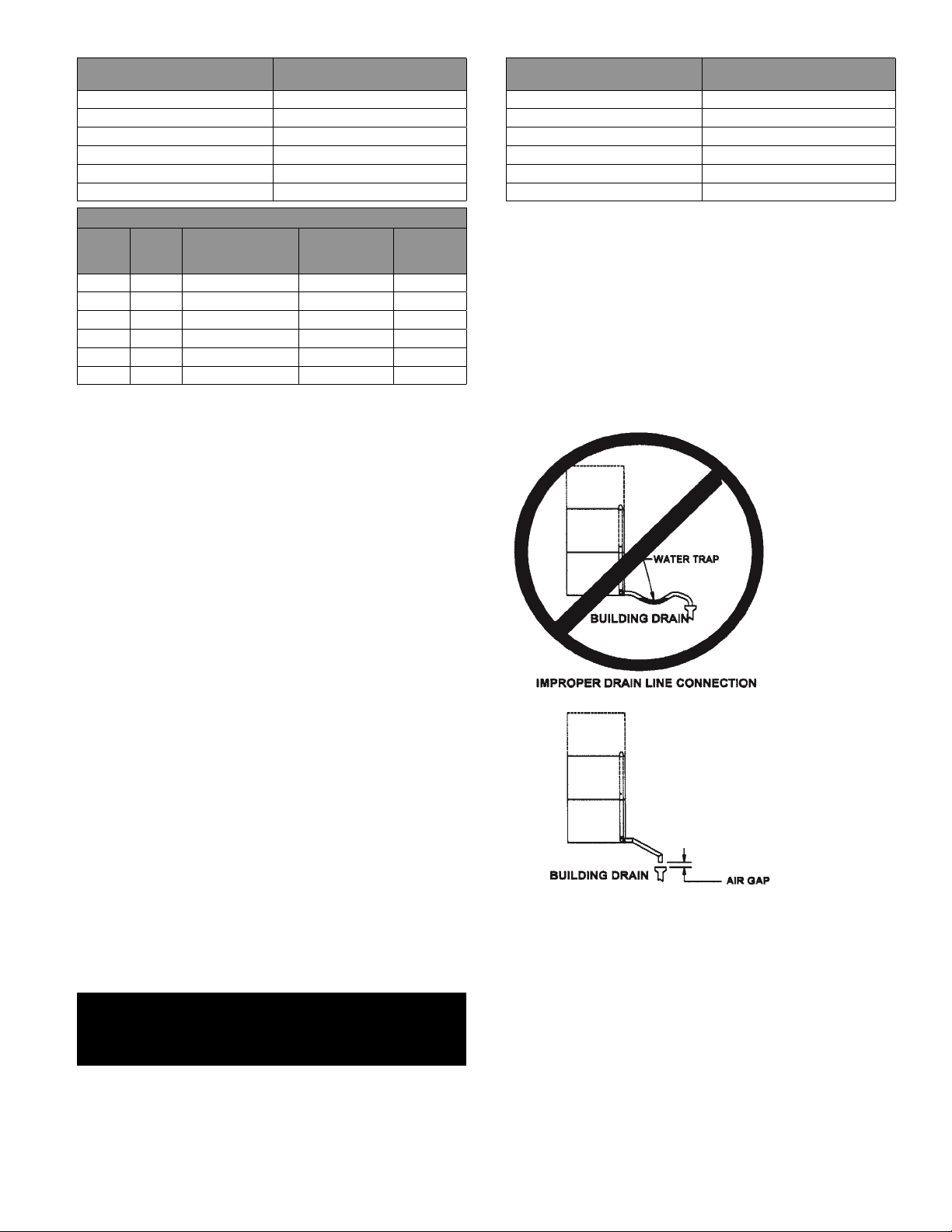
WARNING: DO NOT CONNECT THE DRAIN DIRECTLY TO A BUILDING DRAIN.
WARNING: BLOCKING THE DRAIN IS HAZARDOUS.
IMPORTANT: IMPROPER DRAIN CONNECTION WILL VOID WARRANTY.
IMPORTANT: DO NOT ALLOW ANY WATER TRAPS IN THE DRAIN LINE. A TRAP CAN CAUSE
PRESSURE TO BUILD UP INSIDE THE CAVITY DURING STEAMING, WHICH
WILL MAKE THE DOOR GASKET LEAK.
WARNING: WHEN YOU OPEN THE DOOR, STAY AWAY FROM STEAM COMING OUT OF
THE UNIT. STEAM CAN CAUSE BURNS.
WARNING: BEFORE CLEANING THE OUTSIDE OF THE STEAMER, DISCONNECT THE
ELECTRIC POWER SUPPLY. KEEP WATER AND CLEANING SOLUTIONS OUT
OF CONTROLS AND ELECTRICAL COMPONENTS. NEVER HOSE OR STEAM
CLEAN ANY PART OF THE UNIT.
WARNING: ALLOW COOKING CHAMBER TO COOL COMPLETELY BEFORE CLEANING.
STEAMER Weight (LBS) Weight (KGS)
SSB-3G Table Top 240 109
SSB-3G with Stand 310 141
(2)SSB-3G with Stand 475 215
SSB-5G Table Top 272 123
SSB-5G with Stand 345 156
(2)SSB-5G with Stand 555 252
SSB-10G with Stand 452 205
(2)SSB-10G with Stand 764 347
INSTALLATION & START-UP
WARNING: THE UNIT MUST BE INSTALLED BY PERSONNEL WHO ARE QUALIFIED TO
WORK WITH GAS, ELECTRICITY AND PLUMBING. IMPROPER INSTALLATION
CAN CAUSE INJURY TO PERSONNEL AND/OR DAMAGE TO THE EQUIPMENT.
THE UNIT MUST BE INSTALLED IN ACCORDANCE WITH APPLICABLE CODES.
THE UNIT MUST BE INSTALLED BY A LICENSED PLUMBER OR GAS FITTER
WHEN INSTALLED WITHIN THE COMMONWEALTH OF MASSACHUSETTS.
CAUTION: DO NOT INSTALL THE UNIT WITH THE REAR VENTS BLOCKED OR WITHIN 2
INCHES OF A HEAT SOURCE SUCH AS A BRAISING PAN, DEEP FAT FRYER,
CHARBROILER OR KETTLE.
TO AVOID DRAINAGE PROBLEMS, LEVEL THE UNIT FRONT TO BACK, AND
PITCH SLIGHTLY TO THE FRONT.
A. Installation
Minimum Clearances: SmartSteam100 Boilerless Steamer requires the
following minimum clearances to any surface, combustible or noncombustible.
Right Side: 2 inches Left Side: 2 inches Rear: 6 inches
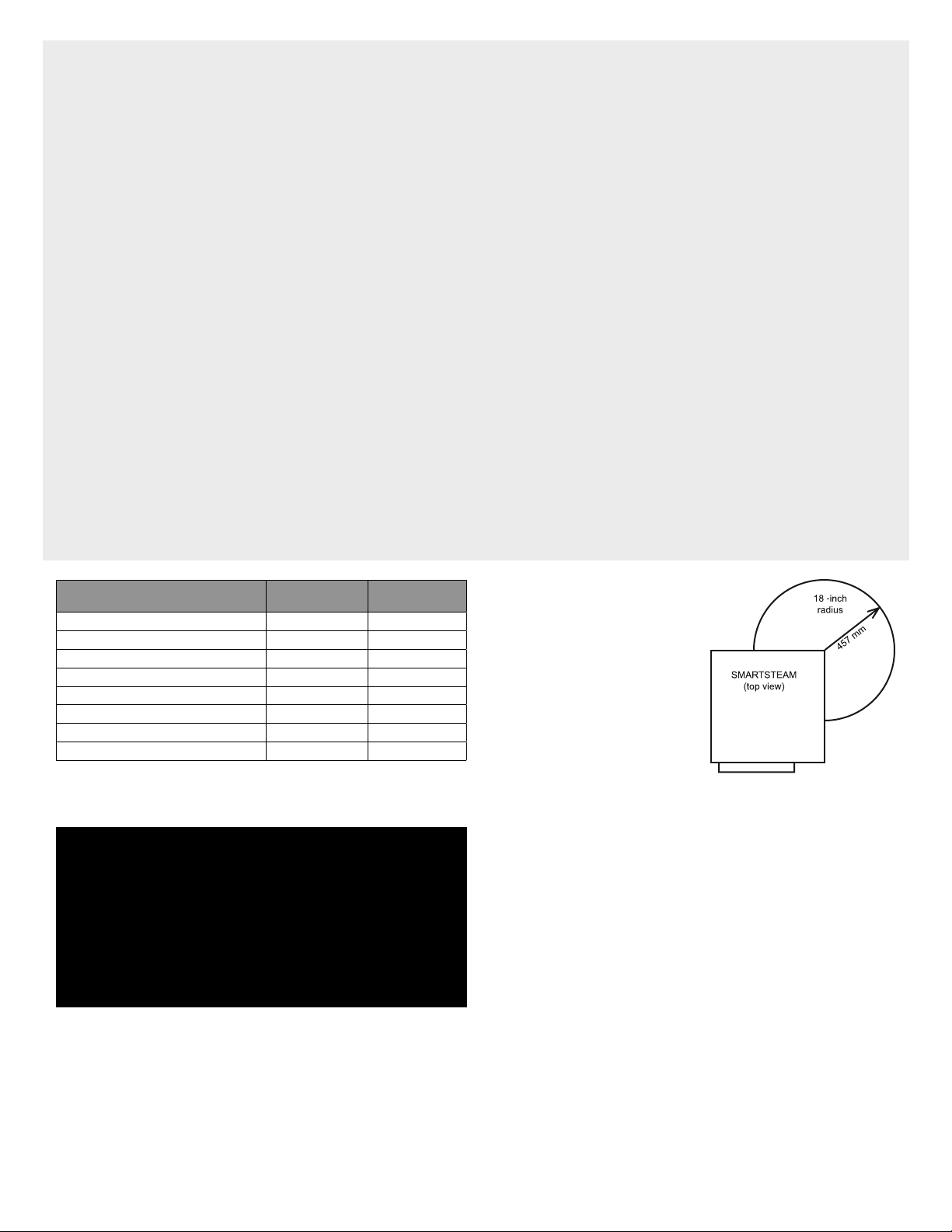
Steam Free Zone:The SmartSteam100 Boilerless Steamer can be damaged by
steam from external sources. Do not install the steamer over a steam venting
drain. Ensure that steam is not present in an area bounded by the footprint of
the steamer and a circle 18 inches in radius about the right rear corner of the
WARNING: USE MILD CLEANING AGENTS ONLY. CAREFULLY READ THE WARNINGS AND
FOLLOW THE DIRECTIONS ON THE LABEL OF EACH CLEANING AGENT. USE
SAFETY GLASSES AND RUBBER GLOVES AS RECOMMENDED BY CLEANING
AGENT MANUFACTURER.
WARNING: DO NOT PUT HANDS OR TOOLS INTO THE COOKING CHAMBER UNTIL THE FAN
HAS STOPPED TURNING.
WARNING: DO NOT OPERATE THE UNIT UNLESS THE REMOVABLE RIGHT SIDE PANEL HAS
BEEN RETURNED TO ITS PROPER LOCATION.
NOTICE: DO NOT USE A CLEANING AGENT THAT CONTAINS ANY SULFAMIC ACID, OR
ANY CHLORIDE, INCLUDING HYDROCHLORIC ACID. IF THE CHLORIDE CONTENT
OF ANY PRODUCT IS UNCLEAR, CONSULT THE MANUFACTURER. DO NOT
USE A CLEANING OR DELIMING AGENT THAT CONTAINS MORE THAN 30%
PHOSPHORIC ACID.
NOTICE: DO NOT USE ANY DEGREASER THAT CONTAINS POTASSIUM HYDROXIDE OR
SODIUM HYDROXIDE OR THAT IS ALKALINE.
WARNING: USE OF ANY REPLACEMENT PARTS OTHER THAN THOSE SUPPLIED BY GROEN
OR THEIR AUTHORIZED DISTRIBUTOR VOIDS ALL WARRANTIES AND CAN
RESULT IN BODILY INJURY TO THE OPERATOR AND DAMAGE THE EQUIPMENT.
SERVICE BY OTHER THAN FACTORY-AUTHORIZED PERSONNEL WILL VOID ALL
WARRANTIES.
WARNING: HIGH VOLTAGE EXISTS INSIDE CONTROL COMPARTMENTS. DISCONNECT
FROM BRANCH CIRCUIT BEFORE SERVICING. FAILURE TO DO SO CAN RESULT
IN INJURY OR DEATH.
steamer (see figure below).
Install and operate the gas appliance
in a well ventilated area. Adequate
air must be supplied to replenish the
air used for combustion. Installation
must conform with local codes and/
or with the Naitonal Fuel Gas Code,
ANSI Z223.1/NFPA-54 (latest edition)
or the National Gas and Propane
Code CSA B149.1 as applicable.
Any item which might obstruct or
restrict the flow of air for combustion and ventilation must be removed. Do not
obstruct the flue cover or rear vents after installation.
THE AREA DIRECTLY AROUND THE APPLIANCE MUST BE CLEARED OF ALL
COMBUSTIBLE MATERIAL. FAILURE TO FOLLOW THESE INSTRUCTIONS CAN
CAUSE BODILY INJURY AND/OR PROPERTY DAMAGE.
The steamer must be disconnected from the gas supply system during any
pressure testing of that system which has test pressures in excess of 1/2 PSI
(3.45 kPa).
B. Electrical Supply Connection
Provide 115 VAC, 60 HZ, 1 PH, 15 AMP service. Bring wire in through hole in
the lower left back panel. Each cavity requires a separate cord for connections.
Local codes and/or the National Electrical Code should be observed in
accordance with ANSI/NFPA 70. AN ELECTRICAL GROUND IS REQUIRED. The
wiring diagram is located in the service compartment and in this manual.
Maximum load is 2-1/2 AMPs. In Canada, provide electrical service in
accordance with the Canadian Electrical Code, CSA C22.2 Part 1 and/or local
codes.
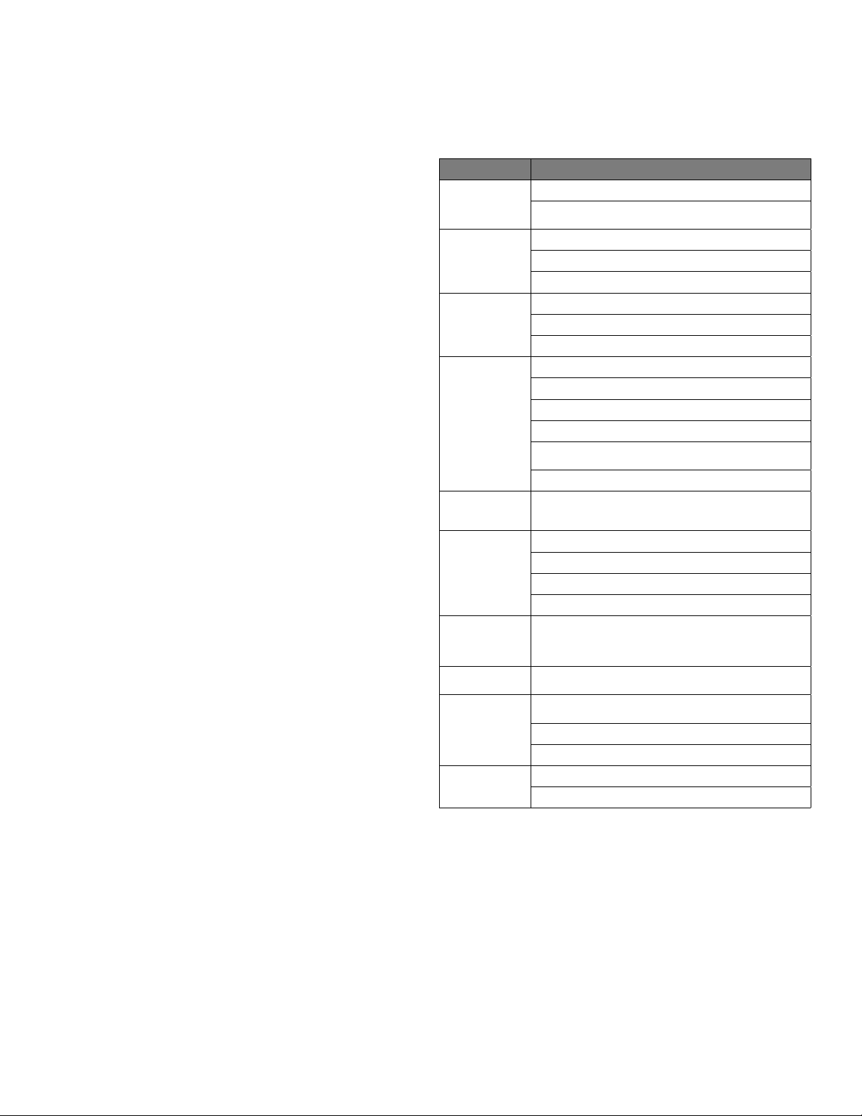
C. Gas Supply Connection
Connection to the gas supply shall be in accordance with the following chart.


 Operator service User manual")

 User manual")


HY-5EF User manual")


HY-5G User manual")