Groen HY-PLUS-DS User manual

This manual provides information for:
PART NUMBER 159499 REV A (04/12)
MODEL HY-PLUS-DS
ATMOSPHERIC
CONVECTION STEAMER
ON A CABINET BASE
· For Models: HY-6SM and HY-10SM
· Capacity: 6 or 10 Steamer Pans (12” x 20” x 2-1/2”)
THIS MANUAL MUST BE RETAINED FOR FUTURE REFERENCE.
READ, UNDERSTAND AND FOLLOW THE INSTRUCTIONS AND
WARNINGS CONTAINED IN THIS MANUAL.
WARNING / FOR YOUR SAFETY
Do not store or use gasoline or other ammable vapors
and liquids in the vicinity of this or any other appliance.
WARNING
Improper installation, adjustment, alteration, service
or maintenance can cause property damage, injury or
death. Read the installation, operating and maintenance
instructions thoroughly before installing or servicing this
equipment.
It is the responsibility of the consignee to inspect the container upon receipt of
same and to determine the possibility of any damage, including concealed dam-
age. Unied Brands suggests that if you are suspicious of damage to make a
notation on the delivery receipt. It will be the responsibility of the consignee to le
a claim with the carrier. We recommend that you do so at once.
Manufacture Service/Questions 888-994-7636.
Information contained in this document is known to be current and accurate at the time
of printing/creation. Unified Brands recommends referencing our product line websites,
unifiedbrands.net, for the most updated product information and specifications.
1055 Mendell Davis Drive
Jackson, MS 39272
888-994-7636, fax 888-864-7636
unifiedbrands.net

2 OM-HY-PLUS-DS

OM-HY-PLUS-DS 3

4 OM-HY-PLUS-DS
Important Operator Warnings .................................................... page 2-3
References..................................................................................... page 4
Equipment Description................................................................... page 5
Installation ................................................................................. page 6-7
Initial Start-Up ............................................................................... page 8
Operation...................................................................................... page 9
Cleaning ........................................................................................ page 10
Maintenance.................................................................................. page 11
Troubleshooting ............................................................................ page 12
Parts List ................................................................................ page 13-19
Electrical Schematics .................................................................. page 20
Service Log .................................................................................. page 21
UNDERWRITERS LABORATORIES, INC.
333 Pngsten Road
Northbrook, Illinois 60062
KLENZADE SALES CENTER
ECOLAB, Inc.
370 Wabasha
St. Paul, Minnesota 55102
800 328-3663 or 612 293-2233
NATIONAL FIRE PROTECTION ASSOCIATION
60 Battery March Park
Quincy, Massachusetts 02269
NFPA/70 The National Electrical Code
NSF INTERNATIONAL
789 North Dixboro Road
P.O. Box 130140
Ann Arbor, Michigan 48113-0140

OM-HY-PLUS-DS 5
The Groen HY-PLUS Steamer is designed to bring you years of service. It has
two stainless steel cavities (cooking chambers) and a control compartment, which
houses the electrical components and steam valves. In each cavity, a powerful blower
circulates the steam for increased heating efficiency. Each cavity will hold up to three
or five steam table pans (12” x 20” x 2-1/2”), depending on the model.
A 16 gauge stainless steel case encloses the cavities and the control compartment
that house electrical components. The door hinges are reversible (the doors may be
hung to open from the left or right).
Operator Controls are located on the front panel.
The steamer cavities are mounted on a cabinet base and require a low pressure (3-
15 PSI) steam supply. The SM Model has no steam generator and requires a “clean”
steam supply suitable for food contact.
The drain system includes a spray condenser, which suppresses any steam escaping
from the chamber and cools condensate water going into the drain.
WARNING
THE UNIT MUST BE INSTALLED BY
PERSONNEL WHO ARE QUALIFIED TO
WORK WITH ELECTRICITY AND PLUMBING.
IMPROPER INSTALLATION CAN CAUSE
INJURY TO PERSONNEL AND/OR DAMAGE TO
THE EQUIPMENT. THE UNIT MUST BE
INSTALLED IN ACCORDANCE WITH ALL
APPLICABLE CODES.
HY-PLUS Series steamers have two steam
compartments with individual controls.

6 OM-HY-PLUS-DS
Immediately inspect the unit for external and internal damage when it is delivered.
Report any damage to the carrier. After inspection, keep the unit in its shipping
container until it is ready to be installed. The unit must be installed level. Level the unit
front to rear and left to right, by adjusting its feet. Check for levelness by using a spirit
level on top of the cabinet, and checking in both directions.
The HY-PLUS SM models have no minimum clearance requirements, but room
should be provided so that the units may be serviced. The use of approved flexible
tubing and quick disconnect attachments will be helpful in allowing the unit to be
moved. For example, 24 inches right side clearance is needed for proper servicing,
unless the unit can be easily moved.
1. Electrical Supply Connection
A. On model HY-6SM, you must provide 115 Volt Alternating Current, 60 Hz,
single phase, 15 AMP service. Local codes and/or the National Electrical
Code should be observed in accordance with ANSI/NFPA-70-1987 (or latest
edition). AN ELECTRICAL GROUND IS REQUIRED.
B. The electrical schematic is located in the electrical enclosure and in this
manual. In Canada provide electrical service in accordance with the Canadian
Electrical Code, CSA C22.1, Part 1 and/or local codes.
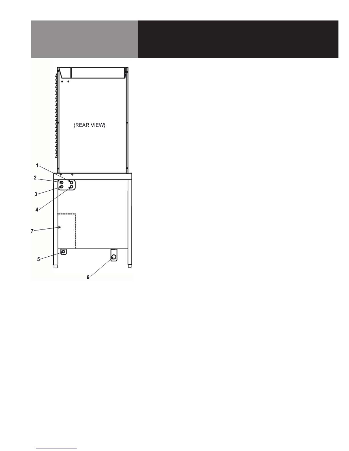
2. Water Supply Connection
A. For the HY-6SM, provide a 3/8” NPT pipe connection for untreated water at
the rear of the unit. A back siphonage device (check valve) must be installed,
complying with local plumbing codes. The water pressure should be between
30 and 60 PSI (210 to 410 kPa). A pressure regulator is required above 60
PSI (410 kPa).
B. The condenser spray uses 0.70 to 0.95 gallons of water per minute (2.6 to
3.6 liters per minute) at 30 to 60 PSI (210 and 410 kPa). The spray will only
operate when a steamer cavity (cooking chamber) is in operation.
C. Water supply lines should be sized to provide for maximum water use (the
total of the boiler and condenser spray) as shown in the following table:
HY-PLUS Steamer condenser spray only
AT 40 PSI (280 kPa) 47.4 (180)
AT 60 PSI (410 kPa) 57.0 (215)
3. Drain Connection
A. On all models, the drain connection is made at the rear of the unit, using
a 1-1/4” NPT pipe. Do NOT use plastic pipe — the piping must be able to
withstand steam and hot water. Extend the drain piping to a nearby floor drain.
Piping of 1 - 1/4” NPT (or 1 - 1/2” NPT) is acceptable for distances of six feet or
less. If the distance to the drain is further than six feet, use 2” NPT piping.
B. Install the drain line with a constant downward pitch. Do not allow any
water traps in the line. A trap can cause pressure to build up inside the
cavity during steaming, which will make the door gasket leak. A vertical
air gap must be maintained between the drain line and the building drain,
unless otherwise specified by local plumbing codes.
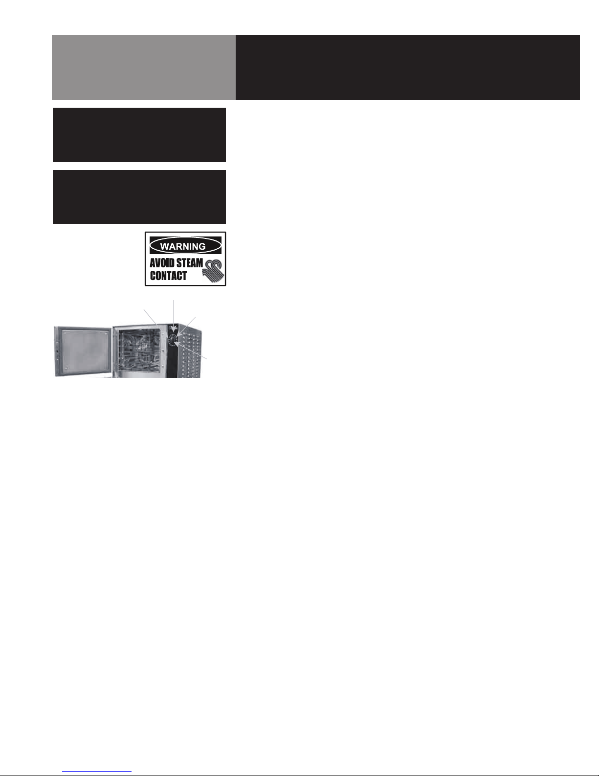
WARNING
THE UNIT MUST BE INSTALLED BY
PERSONNEL WHO ARE QUALIFIED TO
WORK WITH ELECTRICITY AND PLUMBING.
IMPROPER INSTALLATION CAN CAUSE
INJURY TO PERSONNEL AND/OR DAMAGE TO
THE EQUIPMENT. THE UNIT MUST BE
INSTALLED IN ACCORDANCE WITH ALL
APPLICABLE CODES.
CAUTION
SHIPPING STRAPS ARE UNDER TENSION.
THEY CAN SNAP BACK VIOLENTLY AND
CAUSE INJURY WHEN CUT.
CAUTION
MAKING ELECTRICAL OR MECHANICAL
CHANGES TO THE UNIT WITHOUT APPROVAL
FROM THE GROEN FOOD SERVICE
ENGINEERING DEPARTMENT MAY VOID
WARRANTIES.
IMPORTANT
IMPROPER DRAIN CONNECTION
WILL VOID WARRANTY.
Leave an air gap between the hose
and the building drain, and don’t
allow water traps in the line.

OM-HY-PLUS-DS 7
4. Utility Connection
A. HY-PLUS SM DIRECT STEAM) MODEL
1. Hot water (for faucet on 36” and wider units with kettles).
2. Steam inlet.
3. Cold water (for faucet on 36” or wider units with kettles.
4. Cold water (for condenser spray).
5. Not used.
6. Drain (for steamers and condenser spray). Also for kettle condensate
and sink where used.
7. Electrical (conduit through underside, terminals at the right on the
inside).

8 OM-HY-PLUS-DS
Once the unit has been installed, test it to be sure that the unit is working correctly.
1. Remove any literature and packing material from both the interior and the
exterior of the unit.
2. Make certain that the water supply is open.
3. Turn on the electrical power to the unit.
4. When steam is available for the cavity, choose one of the following:
A. Set the timer to the desired time for timed steaming.
B. Turn the timer to the manual ON position for continuous steam.
NOTE: The door must be shut before steam will enter the cavity. If the door is
opened when the timer is on, the flow of steam will stop.
C. Let the steamer sit idle until needed.
5. If the unit will not be used for an extended period, turn off power to the individual
steamer compartments. Turn off power to the gas or electric pressure boiler.
Refer to the steam boiler operator manual, if necessary.
If the unit functions as described above, it is ready for use. If it does not, contact your
Authorized Service Agent.
WARNING
STAY AWAY FROM STEAM COMING OUT
FROM THE UNIT. STEAM CAN CAUSE
SEVERE BURNS.

OM-HY-PLUS-DS 9
Controls: Timers are located on the front right side of the unit. There are two timers
— one each for the upper and lower cavities.
The timer is used in two ways:
1. Turning the timer to any setting delivers steam to the cavity until the timer runs
down to OFF. At that time a red LED switches on and a beeper sounds and the
steam flow to the compartment stops.
2. When turned all the way to the ON position, the timer allows continuous
steaming. A green LED is turned on, and the timer does not time down. Steam
continues until the timer knob is turned to the OFF position.
1. Operating Procedure
A. Turn on the unit’s water supply.
B. Turn on electrical power to the unit.
C. For model SM, turn on the steam supply.
D. Load food into pans so that it is in uniform layers. For best results, pans
should be filled to about the same levels, and should be even on top.
E. Open the door and slide the pans onto the supports. If you will only be
steaming one pan, put it in the middle rack position.
F. Close the door.
NOTE: The door must be closed before steam will enter the cavity. If the
door is opened when the timer is on, the steam will stop.
G. Turn the timer to one of the following settings:
1. If you want to steam for a definite period of time, set the timer to
that time. Steam will be delivered to the cavity for that time, and
then stop. A buzzer and red LED will indicate that the timed cycle is
complete. Steam flow stops.
2. If you want to steam continuously, turn the timer to the ON position.
A green light will come on. Steam will be delivered to the cavity until
the timer is returned to OFF.
H. Open the door.
I. Using a pad or oven mitt to protect your hands, remove the pans from the
steamer.
J. To shut down the unit, turn the Timer to the OFF position.
WARNING
ANY POTENTIAL USER OF THE EQUIPMENT
SHOULD BE TRAINED IN SAFE AND CORRECT
OPERATING PROCEDURES.
WARNING
WHEN YOU OPEN THE DOOR, STAY AWAY
FROM THE STEAM COMING OUT OF THE
UNIT. THE STEAM CAN CAUSE BURNS.
OFF
DONE
ON
TIMER
Timer Controls for each of the two
cavities are identical.

10 OM-HY-PLUS-DS
To keep your HY-PLUS Steamer in proper working condition, clean the unit
each day. This regular cleaning will reduce the effort required to clean the
cavities.
1. Suggested Tools
A. Mild detergent
B. Stainless steel exterior cleaner such as a Spray Degreaser, Zepper®
C. De-greaser, such as EncompasS®, Malone 34®, Puritan Puribrute®, or
Con-Lie®
D. Cloth or sponge
E. Plastic wool or a brush with soft bristles
F. Spray bottle
G. Measuring cup
H. Nylon pad
I. Towels
J. Plastic disposable gloves
2. Procedure
A. Outside
1. Prepare a warm solution of mild detergent as instructed by the
supplier. Wet a cloth with this solution and wring it out. Use the moist
cloth to clean the outside of the unit. Do not allow freely running liquid
to touch the controls, the control panel, any electrical part, or any
panel louver.
2. To remove material which may be stuck to the unit, use plastic wool,
a fiber brush, or a plastic or rubber scraper with a detergent solution.
3. Stainless steel surfaces may be polished with a recognized stainless
steel cleaner such as Zepper®.
B. Inside
Remove the fan/baffle partition from inside the unit and place it into a utility
sink. Wash the cooking chamber(s) and fan/baffle partition with a warm
solution of mild detergent and water. If needed, use a de-greaser with a
plastic scouring pad. Rinse parts thoroughly with clean water and replace
fan/baffle partition. Make sure the drain holes at the back of each cavity
are free of food particles or other debris.
WARNING
DISCONNECT THE POWER SUPPLY BEFORE
CLEANING THE OUTSIDE OF THE STEAMER.
KEEP WATER AND CLEANING SOLUTIONS
OUT OF CONTROLS AND ELECTRICAL
COMPONENTS. NEVER HOSE OR STEAM
CLEAN ANY PART OF THE UNIT.
DON’T MIX DE-LIMING AGENTS (ACID)
WITH DEGREASERS (ALKALI )
ANYWHERE IN THE UNIT.
AVOID CONTACT WITH ANY CLEANERS,
DE-LIMING AGENT OR DE-GREASER AS
RECOMMENDED BY THE SUPPLIER. MANY
ARE HARMFUL. READ THE WARNINGS AND
FOLLOW THE DIRECTIONS!
EVEN WHEN THE UNIT HAS BEEN SHUT OFF,
DON’T PUT HANDS OR TOOLS INTO THE
COOKING CHAMBER UNTIL THE FAN HAS
STOPPED TURNING.
DON’T OPERATE THE UNIT UNLESS
REMOVABLE INTERIOR PARTITIONS HAVE
BEEN PUT BACK IN THEIR
PROPER LOCATIONS.
DON’T USE ANY CLEANING OR DE-LIMING
AGENT THAT CONTAINS ANY SULFAMIC
AGENT OR ANY CHLORIDE, INCLUDING
HYDROCHLORIC ACID (HCl). TO CHECK FOR
CHLORIDE CONTENT SEE ANY MATERIAL
SAFETY DATA SHEETS PROVIDED BY THE
CLEANING AGENT MANUFACTURER. DON’T
USE ANY CLEANING OR DE-LIMING AGENT
THAT CONTAINS MORE THAN
30% PHOSPHORIC ACID.
IMPORTANT
DO NOT USE ANY METAL MATERIAL (SUCH
AS METAL SPONGES) OR METAL IMPLEMENT
(SUCH AS A SPOON, SCRAPER OR WIRE
BRUSH) THAT MIGHT SCRATCH STAINLESS
STEEL SURFACES. SCRATCHES MAKE THE
SURFACE HARD TO CLEAN AND PROVIDE
PLACES FOR BACTERIA TO GROW. DO NOT
USE STEEL WOOL, WHICH MAY LEAVE
PARTICLES IMBEDDED IN THE SURFACE,
WHICH COULD EVENTUALLY CAUSE
CORROSION AND PITTING.

OM-HY-PLUS-DS 11
The Steamer is designed for minimum maintenance, and no user adjustments should
be necessary. Certain parts may need replacement after prolonged use. If there is a
need for service, only personnel or Authorized Service Representatives should do the
work.
Periodic Inspection: It is recommended that service personnel check the unit
thoroughly at least once a year. The inspection should include electrical wires and
connections. The inside of the control compartment should also be thoroughly cleaned.
Door Latch Adjustment: If steam or condensate is observed leaking from around
the door, take the following steps:
1. Check the condition of the door gasket. Replace it if it is cracked or split.
2. Inspect the cooking chamber drain for blockage.
3. Adjust the latch pin to allow for changes that might occur as the gasket ages.
a. Loosen the lock nut at the base of the latch pin, then turn the latch pin ¼
turn clockwise, and tighten the lock nut.
b. After adjustment, run the unit to test for further steam leakage.
c. If there is still leakage, repeat.
d. Continue adjusting the pin clockwise until the door fits tightly enough to
prevent leakage.
e. If leakage is still present, repeat steps a. through c. until leakage stops.
A Maintenance and Service Log is provided at the back of this manual. Each time
maintenance is performed on the unit, enter the date the work was done, what was
done, and who did it.
WARNING
BEFORE REPLACING ANY PART TURN OFF
THE ELECTRICAL POWER TO THE UNIT.
DEATH OR INJURY COULD RESULT FROM
CONTACT WITH HIGH VOLTAGE.

12 OM-HY-PLUS-DS
The Steamers are designed to operate smoothly and efficiently when properly maintained. However, the following is a list of things
to check if there is a problem. Wiring diagrams are furnished inside the service panel.
SYMPTOM WHAT TO CHECK
Timer control will not operate. a. Is the electrical supply turned on?
b. Is the ON/OFF switch in the base cabinet turned on?
c. Is the green light in the ON/OFF switch lit?
d. Are any fuses blown?
No steam to cavities. a. On HY-6SM: Is steam supply turned on?
b. Is the door closed? (Doors must be closed before steam will enter the
cavity).
Door leaking steam or water. a. Are the drain holes at the rear of the cavity blocked?
b. Does the door gasket need replacement?
c. Is the door latch in need of adjustment? (See the Maintenance section).
d. Is the unit level?
Excessive steam coming from the vent
pipe.
a. Is the water supply turned on?
b. Is the condenser hose kinked or obstructed?
c. Is the condenser spray solenoid working?

OM-HY-PLUS-DS 13
Steamer Cavity Only

14 OM-HY-PLUS-DS
Key Description Part #
1 Upper Cavity Drain Hose 088847
2 Motor Assembly 096740
3 Timer 096826
4 Knob, Timer 123100
5 PC Board, HY-Plus Light and Timer 130457
6 Bracket, Board Mtg 096888
7 Steamer Control Board 102222
8 Capacitor, 6 mfd - SM 096812
9 Shield, Motor Drip 119844
10 Nut, Rotary Shaft Seal 101145
11 Nut, Keps 6-32 071289
12 Harness, Upper Control 130450
13 Post, PC Board Mtg 099901
14 Screw, 6-32 069777
15 Jumper, Voltage Select - SM & SG 100959
16 Harness, Spray Vavle - SM 137834
17 Cable Clamp 087958
18 Nut, 10-32 071256
19 Nut, 8-32 002632
Key Description Part #
31 Valve, Safety 143470
32 Manifold Fitting 099249
33 Gasket 099250
34 Nut, 1/4-20 012940
35 Tee 013201
36 Solenoid Valve 113014
37 Nipple, 3/8 013202
38 Connector 054493
39 Tube, Upper 100551
40 Elbow 042364
41 Tee 100553
42 Tube, Supply 100552
43 Lower Cavity Drain Hose 088848
Steamer Cavity Only

OM-HY-PLUS-DS 15
Key Description Part #
1 Motor 096739
2 Slinger Washer 096831
3 Motor Mounting Plate 094134
4 Shaft Seal 096868
5 Plate Seal Holder 096752
Motor/Fan
Assembly

16 OM-HY-PLUS-DS
Key Description Part #
1 Cover, Right Side (6-Pan) 143778
1 Cover, Right Side (10-Pan) 159866
2 Cover, Left Side (6-Pan) 123184
2 Cover, Left Side (10-Pan) 159867
3 Cover Assembly, Top 123182
4 Screw, 10-32 x 3/8 Truss
Head
004173
5 Retainer, Top 123156
6 Screw, 8-32 x 3/8 slotted
hex head
004173
7 Door Handle 129723
8 Door Hinge 094143
8 Door Hinge (10-Pan) 125928
9 Outer Door (6-Pan) 130858
9 Outer Door (10-Pan) 125922
Sheet Metal
& Doors

OM-HY-PLUS-DS 17
Key Description Part #
1 Door Gasket (6-Pan) 094147
1 Door Gasket (10-Pan) 125907
2 Door Handle 070123
3 Door Cam 074252
4 Magnet Assembly 069762
5 U-Channel Assy. (6-Pan)
(Incl. Door Spring 078911)
094144
5 U-Channel Assy. (10-Pan)
(Incl. Door Spring 078911)
125925
6 Latch Spring 078911
7 Latch Pin 078914
X Left Pan Rack (6-Pan) 094148
X Left Pan Rack (10-Pan) 125901
8 Lock Nut 003823
9 Inner Panel (6-Pan) 130863
9 Inner Panel (10-Pan) 125927
10 Door Spacer 071206
11 Door Screws 05764
12 Door Hinge (6-Pan) 130868
12 Door Hinge (10-Pan) 125928
13 Outer Door (6-Pan) 130858
13 Outer Door (10-Pan) 125922
X Insulate Board (6-Pan) 094142
X Insulate Board (10-Pan) 125926
X Blower Cover/Right Pan
Rack (6-Pan)
096788
X Blower Cover/Right Pan
Rack (10-Pan)
125902
X= not shown
Door & Cavity
Hardware

18 OM-HY-PLUS-DS
Key Description Part #
1 Solenoid Valve
(Spray Condenser)
099221
2 Hose d “ ID x 8” Long 099282b
3 Rubber Flap 099213
4 Spacer 099212
5 Hose, Outlet 1 “ID x 3” Long 099280b
6 Anchor Coupling, d” NPT N89267
Drain Box with
Spray Condenser

OM-HY-PLUS-DS 19
Key Description Part #
1 Weld Assembly,
Electrical Cabinet
137257
2 Terminal Block, 2-Pole 003887
3 Lug, Ground 119829
4 Bracket, Electronic
Cabinet Breaker
137254
5 Bushing, Strain Relief 121742
6 Screw, Hex Slot Washer HD
Cap, 8-32 x 1/4” Long
074242
7 Screw Round HD,
8-32 x 1 1/4” Long
005056
8 Weld Assembly, Electronic
Cabinet Bottom
137256
9 Screw, Hex HD,
10-32 x 3/8” Long
069773
10 Plate, Hole Cover 137749
11 Hole Plug, 7/8” Dia. 137553
12 Harness, Power Cord,
HY-6SM
137842
13 Nut, Hex Keps, #8-32 069784
Electrical Controls

20 OM-HY-PLUS-DS
Steamer Cavities
Table of contents
Other Groen Electric Steamer manuals

Groen
Groen HYPERSTEAM HY-6E User manual

Groen
Groen HYPERSTEAM HY-6E User manual

Groen
Groen HY-3E User manual

Groen
Groen HY-3E User manual

Groen
Groen HyPlus HY-6S Series User manual

Groen
Groen GROEN HYPERSTEAM HY-6E(CE) Operator service User manual

Groen
Groen HY-3E User manual

Groen
Groen GROEN HYPERSTEAM HY-6G(CE) User manual

Groen
Groen HY-3E User manual

Groen
Groen HYPERSTEAM (2)HY-5EF User manual