Groen HYPERSTEAM HY-6E User manual

This manual provides information for:
OPERATOR MANUAL
IMPORTANT INFORMATION, KEEP FOR OPERATOR
PART NUMBER 148668, REV G (03/16)
HY-6E
HYPERSTEAM™
ATMOSPHERIC CONVECTION
STEAMER
· Self Contained
· Electric Heated
· Capacity: 6 Steamer Pans
(12” x 20” x 2 1/2”)
Information contained in this document is known to be current and accurate at the time
of printing/creation. Unified Brands recommends referencing our product line websites,
unifiedbrands.net, for the most updated product information and specifications.
1055 Mendell Davis Drive
Jackson, MS 39272
888-994-7636, fax 888-864-7636
unifiedbrands.net
THIS MANUAL MUST BE RETAINED FOR FUTURE REFERENCE.
READ, UNDERSTAND AND FOLLOW THE INSTRUCTIONS AND
WARNINGS CONTAINED IN THIS MANUAL.
WARNING / FOR YOUR SAFETY
Do not store or use gasoline or other ammable vapors
and liquids in the vicinity of this or any other appliance.
WARNING
Improper installation, adjustment, alteration, service
or maintenance can cause property damage, injury or
death. Read the installation, operating and maintenance
instructions thoroughly before installing or servicing this
equipment.
NOTIFY CARRIER OF DAMAGE AT ONCE
It is the responsibility of the consignee to inspect the container upon receipt of
same and to determine the possibility of any damage, including concealed dam-
age. Unied Brands suggests that if you are suspicious of damage to make a
notation on the delivery receipt. It will be the responsibility of the consignee to le
a claim with the carrier. We recommend that you do so at once.
Manufacture Service/Questions 888-994-7636.

2 OM-HY/6E
IMPORTANT - READ FIRST - IMPORTANT
WARNING: THE UNIT MUST BE INSTALLED BY PERSONNEL QUALIFIED TO WORK WITH ELECTRICITY AND
PLUMBING. IMPROPER INSTALLATION CAN CAUSE INJURY TO PERSONNEL AND/OR DAMAGE TO
THE EQUIPMENT. THE UNIT MUST BE INSTALLED IN ACCORDANCE WITH APPLICABLE CODES.
CAUTION: SHIPPING STRAPS ARE UNDER TENSION AND CAN SNAP BACK WHEN CUT.
CAUTION: DO NOT INSTALL THE UNIT IN ANY WAY WHICH WILL BLOCK THE RIGHT SIDE VENTS, OR WITHIN 12
INCHES OF A HEAT SOURCE SUCH AS A BRAISING PAN, DEEP FRYER, CHARBROILER OR KETTLE.
CAUTION: LEVEL THE UNIT FRONT TO BACK, OR PITCH IT SLIGHTLY TO THE REAR, TO AVOID DRAINAGE
PROBLEMS.
WARNING: TO AVOID DAMAGE OR INJURY, FOLLOW THE WIRING DIAGRAM EXACTLY WHEN CONNECTING A
UNIT.
CAUTION: DO NOT USE PLASTIC PIPE. DRAIN MUST BE RATED FOR BOILING WATER.
WARNING: DO NOT CONNECT THE DRAIN DIRECTLY TO A BUILDING DRAIN.
WARNING: BLOCKING THE DRAIN IS HAZARDOUS.
IMPORTANT: IMPROPER DRAIN CONNECTION WILL VOID WARRANTY.
IMPORTANT: DO NOT ALLOW ANY WATER TRAPS IN THE DRAIN LINE. A TRAP CAN CAUSE PRESSURE TO BUILD
UP INSIDE THE CAVITY DURING STEAMING, WHICH WILL MAKE THE DOOR GASKET LEAK.
WARNING: WHEN YOU OPEN THE DOOR, STAY AWAY FROM STEAM COMING OUT OF THE UNIT. STEAM CAN
CAUSE BURNS.
WARNING: BEFORE CLEANING THE OUTSIDE OF THE STEAMER, DISCONNECT THE ELECTRIC POWER SUPPLY.
KEEP WATER AND CLEANING SOLUTIONS OUT OF CONTROLS AND ELECTRICAL COMPONENTS.
NEVER HOSE OR STEAM CLEAN ANY PART OF THE UNIT.
WARNING: ALLOW COOKING CHAMBER TO COOL BEFORE CLEANING.
WARNING: CAREFULLY READ THE WARNINGS AND FOLLOW THE DIRECTIONS ON THE LABEL OF EACH
CLEANING AGENT. USE SAFETY GLASSES AND RUBBER GLOVES AS RECOMMENDED BY DE-LIMING
AGENT MANUFACTURER.
WARNING: DO NOT MIX DE-LIMING AGENTS (ACID) AND DE-GREASERS (ALKALI).
WARNING: DO NOT PUT HANDS OR TOOLS INTO THE COOKING CHAMBER UNTIL THE FAN HAS STOPPED
TURNING.
WARNING: DO NOT OPERATE THE UNIT UNLESS THE REMOVABLE LEFT AND RIGHT SIDE PANELS HAVE BEEN
RETURNED TO THEIR PROPER LOCATIONS.
NOTICE: DO NOT USE A CLEANING OR DE-LIMING AGENT THAT CONTAINS ANY SULFAMIC ACID OR ANY
CHLORIDE, INCLUDING HYDROCHLORIC ACID. IF THE CHLORIDE CONTENT OF ANY PRODUCT IS
UNCLEAR, CONSULT THE MANUFACTURER.

OM-HY/6E 3
NOTICE: DO NOT USE ANY DE-GREASER THAT CONTAINS POTASSIUM HYDROXIDE OR SODIUM HYDROXIDE
OR THAT IS ALKALINE.
WARNING: USE OF ANY REPLACEMENT PARTS OTHER THAN THOSE SUPPLIED BY GROEN OR THEIR
AUTHORIZED DISTRIBUTOR VOIDS ALL WARRANTIES AND CAN RESULT IN BODILY INJURY TO THE
OPERATOR AND DAMAGE THE EQUIPMENT. SERVICE BY OTHER THAN FACTORY AUTHORIZED
PERSONNEL WILL VOID ALL WARRANTIES.
WARNING: HIGH VOLTAGE EXISTS INSIDE CONTROL COMPARTMENTS. DISCONNECT FROM BRANCH BEFORE
SERVICING. FAILURE TO DO SO CAN RESULT IN SERIOUS INJURY OR DEATH.
IMPORTANT - READ FIRST - IMPORTANT

4 OM-HY/6E
Important Operator Warnings ....................................................page 2-3
References.................................................................................... page 4
Equipment Description.................................................................. page 5
Inspection and Unpacking ............................................................ page 5
Water Quality & Treatment.............................................................. page 6
Installation & Start-Up ................................................................ page 7-8
Operation ................................................................................ page 9-10
Cleaning.................................................................................. page 11-12
Maintenance................................................................................. page 13
Troubleshooting............................................................................ page 13
Electrical Schematic ..................................................................... page 28
Service Log ................................................................................. page 29
UNDERWRITERS LABORATORIES, INC.
333 Pngsten Road
Northbrook, IL 60062
NSF INTERNATIONAL
P.O Box 130140
789 N. Dixboro Road
Ann Arbor, MI 48105, USA
NFPA – NATIONAL FIRE PROTECTION ASSOCIATION
1 Batterymarch Park
Quincy, MA 02169
ANSI – AMERICAN NATIONAL STANDARDS INSTITUTE
1899 L Street, NW, 11th Floor
Washington, DC 20036
CSA INTERNATIONAL
178 Rexdale Blvd.
Toronto, ON
Canada M9W 1R3
ICC – INTERNATIONAL CODE COUNCIL
500 New Jersey Avenue, NW
6th Floor, Washington, DC 20001
Table of Contents
References

OM-HY/6E 5
Your Groen HY-6E HyPerSteam Convection Steamer is designed to give years of
service. It has two stainless steel cavities (cooking chambers) which are served by
twin, independent atmospheric steam generators which are electrically heated. A
powerful blower circulates the steam in each cavity to increase heating efficiency.
Each cavity holds up to three steam table pans (12” x 20” x 2½”). An 18 gauge
stainless steel case encloses the cavities, the steam generators and the control
compartment that houses electrical components. Door hinges are reversible (the doors
may be set to open from the left or right). Operating Controls are on the front panel.
HY-6E steamers are equipped with fully electronic controls and a button-activated,
preprogrammed CLEAN cycle. The On-Off switch is a touch pad control, and the
distinctive symbol for steam is integrated into the panel design.
The drain system includes a spray condenser, which helps keep steam from escaping
down the condensate drain.
Equipment Description
The HY-6E has two independent cavities, each
with its own base-mounted steam generator.
Inspection & Unpacking
The HY-6E will be delivered completely assembled in a heavy crate attached to a skid.
On receipt, inspect the crate carefully for exterior damage.
Carefully cut the straps around the crate and detach the crate from the skid. Be careful
to avoid personal injury or equipment damage from staples which might be left in the
crating.
Write down the model number, serial number and installation date. Keep this information
for reference. Space for these entries is provided at the top of the Service Log in the
back of this manual.
When starting installation, lift the unit straight up off the skid. Check packing materials
to make sure loose parts such as the condensate drip tray are not discarded with the
packing material.
CAUTION
SHIPPING STRAPS ARE UNDER TENSION
AND CAN SNAP BACK WHEN CUT.
CAUTION
THIS UNIT WEIGHS 550 POUNDS. GET HELP
AS NEEDED AND USE MATERIAL HANDLING
EQUIPMENT TO MOVE IT.

6 OM-HY/6E
Water Quality & Treatment
It is essential that the steam generator be supplied with water that will not form scale
at an unacceptable rate. The boiler was engineered to minimize scale, but its formation
depends on water hardness and how much the unit is used.
In some areas of the United States the water is low enough in mineral content to avoid
scale build-up. However, most water supplies carry heavy loads of minerals. This
will form scale in the steam generator, reduce its steam output, and possibly cause
premature component failure.
Your water utility or local water quality dealer can tell you about the minerals in your
water. The water going to the steam generator should have:
1. Between 1 and 30 ppm total dissolved solids (TDS)
2. A pH (acidity rating) of 7.0 - 8.0
3. Total alkalinity less than 120 ppm
4. Silica less than 13 ppm
5. Chlorides less than 30 ppm
6. Sulfates less than 40 ppm
7. Chlorine less than 10 ppm
Please follow these simple precautions:
1. Do not rely on unproven water treatment equipment which is sold for scale
prevention or scale removal. They frequently don’t work. The best way to prevent
scale is to supply the purest possible water.
2. If your water contains scale-forming minerals, as most water does, use a well
maintained water treatment system. Whether an exchangeable softener cartridge
or a regenerating system is chosen, a regular exchange system is essential.
3. Installing a water meter on supply line to the steamer will provide an accurate
gauge of water use, and will help determine when to exchange cartridges or
regenerate the softener. Using treated water will provide longer generator life,
higher steam capacity, and reduce maintenance requirements.
4. If you notice a slowdown in steam production, check the steam generator for scale
build-up. Heavy scale reduces the unit’s ability to boil water, and can even cause
heating elements in the steam generator to overheat and burn out.
5. Steamers are available with two separate water intakes:
one for the steam generator (treated water)
one for the spray condenser (untreated water).
The steam generator only uses 14 to 31% of a steamer’s water. Since water
treatment systems are typically sized by total GPH (gallons per hour), the second
intake could reduce treatment requirements by up to 80%, resulting in significant
savings.
REDUCE SCALE PROBLEMS BY USING
AND MAINTAINING A WATER SOFTENER
FOR YOUR STEAMER!

OM-HY/6E 7
Installation & Start-Up
WARNING
THE UNIT MUST BE INSTALLED BY
PERSONNEL WHO ARE QUALIFIED TO
WORK WITH ELECTRICITY AND PLUMBING.
IMPROPER INSTALLATION CAN CAUSE
INJURY TO PERSONNEL AND/OR DAMAGE
TO THE EQUIPMENT. THE UNIT MUST
BE INSTALLED IN ACCORDANCE WITH
APPLICABLE CODES.
ELECTRICAL SUPPLY CONNECTION
1. Panel Removal
Open the wiring and control panel by removing the screws on the right side panel.
Slide the panel forward, and set it aside.
2. Supply Voltage
The unit must be operated at the rated nameplate voltage.
3. Phase Selection
Refer to heater schematics (Page 28) for wiring information.
4. Terminal Block
The terminal block for incoming power is located at the back of the control
compartment. The ground terminal is located in the wiring compartment near
the terminal block. The unit must have a separate ground wire for safe operation.
Minimum size for the ground wire is 10 AWG.
5. Supply Wire
To determine the type of wire you need for the power supply, find the operating
voltage and number of phases on the unit data plate. Refer to the table below or
to the label on the unitʼs back for correct wire size and temperature rating. The
equipment grounding wire must comply with the National Electrical Code (NEC)
requirements. The schematic on the inside of the unitʼs right side cover gives
directions for proper connection of the terminal block jumpers. The specified
wire must be used, or the unit will not meet Underwriters Laboratories and NEC
requirements. The knockout hole is sized for a 1 inch conduit fitting. Pass the wire
up the back through this knockout hole to the front. Make the connections from the
front.
FIELD WIRING TABLE - USE COPPER WIRE ONLY - INSULATION RATING THHN (90ºC)
VOLTAGE WIRING REQUIRED MAXIMUM
CURRENT POWER
208 1 PHASE #2 AWG COPPER ONLY, AT LEAST 75ºC
#3 AWG COPPER ONLY, AT LEAST 90ºC 92 AMP 19 KW
208 3 PHASE #4 AWG COPPER ONLY, AT LEAST 75ºC
#6 AWG COPPER ONLY, AT LEAST 90ºC 53 AMP 19 KW
240 1 PHASE #3 AWG COPPER ONLY, AT LEAST 75ºC
#4 AWG COPPER ONLY, AT LEAST 90ºC 80 AMP 19 KW
240 3 PHASE #6 AWG COPPER ONLY, AT LEAST 75ºC
#8 AWG COPPER ONLY, AT LEAST 90ºC 46 AMP 19 KW
480 3 PHASE #10 AWG COPPER ONLY, AT LEAST 75ºC
#10 AWG COPPER ONLY, AT LEAST 90ºC 23 AMP 19 KW
480 1 PHASE #10 AWG COPPER ONLY, AT LEAST 75ºC
#10 AWG COPPER ONLY, AT LEAST 90ºC 40 AMP 19 KW
CAUTION
DO NOT INSTALL THE UNIT WITH THE RIGHT
OR LEFT SIDE VENTS BLOCKED OR WITHIN
12 INCHES OF A HEAT SOURCE (SUCH AS A
BRAISING PAN, DEEP FRYER, CHAR BROILER
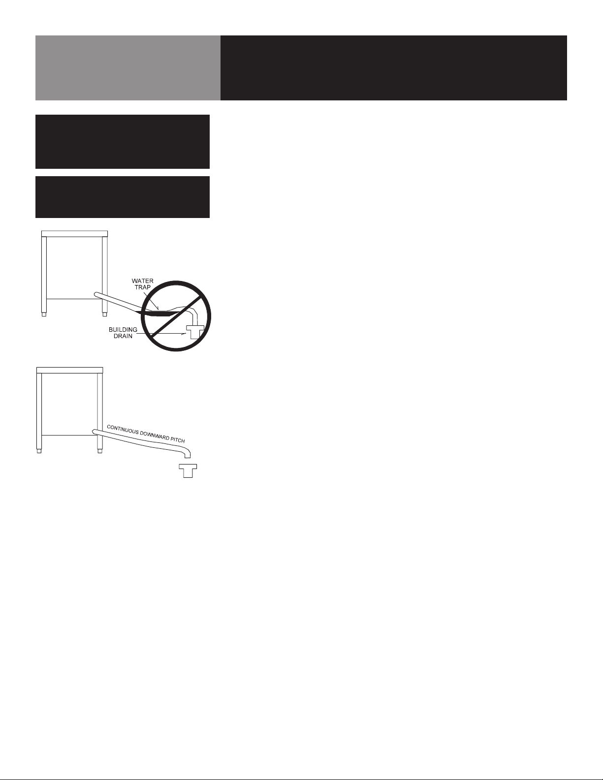
OR KETTLE). TO AVOID DRAINAGE PROBLEMS,
LEVEL THE UNIT FRONT TO BACK.
CAUTION
EACH UNIT MUST HAVE A SEPARATE
GROUND WIRE FOR SAFE OPERATION.
WARNING
TO AVOID DAMAGE OR PERSONAL INJURY,
FOLLOW THE ELECTRICAL SCHEMATIC
EXACTLY WHEN CONNECTING THE UNIT.

8 OM-HY/6E
6. Branch Circuit Protection
Each conductor must have over-current protection. Refer to the label on the back
of the unit for the proper wire type and size. Connections to the unit must be
watertight. We strongly recommend that the HY-6E Steamer have its own branch
circuit protection. Current and power demands for the different units are as follows:
WATER CONNECTION(S)
Install a check valve to prevent back flow in the incoming cold water line, as required by
local plumbing codes. Water pressure in the line should be between 30 and 60 PSIG and
must deliver a flow rate of 1.5 to 3.0 gallons per minute. If pressure is above 60 PSIG, a
pressure regulator will be needed.
A ¾ inch female NH connector (garden hose type) is used to attach the water supply to
the inlet valve. Minimum inside diameter of the water feed line is ½ inch. Use a washer
in the hose connection. Do not allow the connection to leak, no matter how slowly. If
you have the dual water connection option, put the treated water (softened) to the right
intake (looking from the rear of the unit), and untreated water to the left. Connections for
both are made as described above.
DRAIN CONNECTION
The HY-6E Steamer must be leveled front to back. A 1½ inch (38mm) ID hose may be
attached to the drain pipe by means of a hose.
Do NOT use plastic pipe. The drain must withstand boiling water.
Install the drain line with a constant downward pitch. Do not allow any water traps in
the line. A trap can cause pressure to build up inside the cavity during steaming, which
will make the door gasket leak. IMPROPER CONNECTION OF THE DRAIN WILL VOID YOUR
WARRANTY
Installation & Start-Up
WARNING
DO NOT CONNECT THE DRAIN DIRECTLY TO A
BUILDING DRAIN. BLOCKING THE DRAIN IS
HAZARDOUS.
CAUTION
DO NOT USE PLASTIC PIPE. DRAIN MUST BE
RATED FOR VERY HOT WATER.
Don’t allow water traps in the hose.

OM-HY/6E 9
CONTROLS
Operator controls are on the front right of the unit. The control panel has the following
touch pads and indicator lights:
The timer is used in three ways:
1. The ON/OFF touch pad gets the HyPerSteam ready for use, or shuts it off.
2. The READY indicator light shows that the steam generator is at standby
temperature and the cavity is hot enough to begin steaming.
3. When one probe is covered with lime scale or fails, the DELIME light flashes briefly
every few seconds, but the unit will continue to operate. Delime the unit as soon
as possible. The DELIME light will flash until power is removed from the unit, or the
unit goes through a clean cycle.
4. If the problem continues, both probes may fail. Then the steamer stops working,
and the SERVICE light is lit. If DELIMING/CLEANING does not correct, turn off the
power and contact an Authorized Groen Service Representative for repair.
5. The DELIME indicator light is lit when the unit is operating in the cleaning mode.
6. The HI TEMP indicator light comes on when the steam generator is too hot. The
unit will automatically shut off, and cannot be turned on again until the steam
generator cools and the HI TEMP indicator light goes out.
7. The TIMING indicator light stays on when the timer is running.
8. The CLEAN touch pad is used to start the automatic 50 minute deliming cycle.
9. The timer is used in three ways:
a. In the OFF position the steam generator stays at a low boil or “holding”
temperature.
b. When a cook time is set, the unit steams until the timer runs down to OFF. At
that time steaming stops, a red light comes on and a beeper sounds.
c. With the timer turned to the ON position, the unit steams continuously. The
green light stays lit. The steamer will not time down.
Operation
WARNING
ANY POTENTIAL USER OF THE EQUIPMENT
SHOULD BE TRAINED IN SAFE AND CORRECT
OPERATING PROCEDURES.
WARNING
WHEN YOU OPEN THE DOOR, STAY AWAY
FROM THE STEAM COMING OUT OF THE
UNIT. THE STEAM CAN CAUSE BURNS.
Done Light
Manual
Position/Light
Steamer Timer
Timing
Indicator Light
Power On/Off
Touch Pad
Power
Indicator Light
Ready
Indicator Light
Service
(“De-Lime Me”)
Indicator Light
Cleaning
Indicator Light
Clean Cycle
Touch Pad
High Temp
Indicator Light

10 OM-HY/6E
Operation
OPERATING PROCEDURE
1. Press the ON switch/pad for the steamer. The steam generator will fill, and heat
until the READY light comes on. (About 10 minutes.)
2. Load food into pans in uniform layers. Pans should be filled to about the same
levels, and be even on top.
3. Open the door and slide the pans onto the supports. If you will only be steaming
one pan, put it in the middle position.
4. Close the door. With the READY indicator lit, take one of the following steps:
• If you want to steam the food for a certain length of time, set the timer for
that period. The timer will automatically run the steamer for the set time
and then turn it off. A red light will come on and a beeper will sound. Steam
production stops.
• To steam continuously, turn the timer to the manual ON position. A green light
will come on. The unit will continue steaming until you stop it by turning the
timer to OFF. When steaming continuously YOU MUST CONTROL STEAMING
TIME.
5. Open the door. Remove the pans from the steamer, using hot pads or oven mitts to
protect your hands from the hot pans.
6. To shut down the unit, press the ON/OFF touch pad to OFF. The steam generator
will automatically drain.
WARNING
WHEN YOU OPEN THE DOOR, STAY AWAY
FROM THE STEAM COMING OUT OF THE
UNIT. THE STEAM CAN CAUSE BURNS.

OM-HY/6E 11
Cleaning
WARNING
DISCONNECT THE POWER SUPPLY BEFORE
CLEANING THE OUTSIDE OF THE STEAMER.
KEEP WATER AND CLEANING SOLUTIONS
OUT OF CONTROLS AND ELECTRICAL
COMPONENTS. NEVER HOSE OR STEAM
CLEAN ANY PART OF THE UNIT.
DON’T MIX DE-LIMING AGENTS (ACID) WITH DE-
GREASERS (ALKALI) ANYWHERE IN THE UNIT.
AVOID CONTACT WITH ANY CLEANERS,
DE-LIMING AGENT OR DE-GREASER AS
RECOMMENDED BY THE SUPPLIER. MANY
ARE HARMFUL. READ THE WARNINGS AND
FOLLOW THE DIRECTIONS!
EVEN WHEN THE UNIT HAS BEEN SHUT OFF,
DON’T PUT HANDS OR TOOLS INTO THE
COOKING CHAMBER UNTIL THE FAN HAS
STOPPED TURNING.
DON’T OPERATE THE UNIT UNLESS THE TWO
REMOVABLE INTERIOR PARTITIONS HAVE BEEN
PUT BACK IN THEIR PROPER LOCATIONS.
DON’T USE ANY CLEANING OR DELIMING
AGENT THAT CONTAINS ANY SULFAMIC
AGENT OR ANY CHLORIDE, INCLUDING
HYDROCHLORIC ACID (HCl). TO CHECK FOR
CHLORIDE CONTENT SEE ANY MATERIAL
SAFETY DATA SHEETS PROVIDED BY THE
CLEANING AGENT MANUFACTURER.
To keep your HY-6E Steamer in proper working condition, use the following procedure
to clean the unit. This regular cleaning will reduce the effort required to clean the
steam generator and cavity.
SUGGESTED TOOLS
1. Mild detergent
2. Stainless steel exterior cleaner such as Zepper®
3. Steam generator de-liming agent, such as Groen Delimer Descaler. A liquid
de-liming agent will be easier to use than crystals or powders. See the warning
about chlorides.
4. De-greaser
5. Cloth or sponge
6. Plastic wool or a brush with soft bristles
7. Spray bottle
8. Measuring cup
9. Nylon pad
10. Towels
11. Plastic disposable gloves
12. Funnel
PROCEDURE
1. Outside
a. Prepare a warm solution of the mild detergent as instructed by the sup-
plier. Wet a cloth with this solution and wring it out. Use the moist cloth to
clean the outside of the unit. Do not allow freely running liquid to touch the
controls, the control panel, any electrical part, or any open louver.
b. To remove material which may be stuck to the unit, use plastic wool, a fiber
brush, or a plastic or rubber scraper with a detergent solution.
c. Stainless steel surfaces may be polished with a recognized stainless steel
cleaner such as Zepper®.
2. Steam Generator and Cooking Chamber
The steamer cavity and steam generator may be cleaned separately. Regular de-
liming, depending on your steamer usage and local water quality, must be done
to enhance performance and prolong the life of your HyPerSteam™ convec-
tion steamer. Steamer must be turned off after every use to prevent lime scale
buildup - do not run steamer continuously. When cleaning is scheduled, or the
SERVICE light is on, follow the simple deliming instructions on the next page.
NOTE: ALWAYS USE HOT PADS OR MITTS WHEN HANDLING HOT STEAMER PAN-
ELS OR RACKS. DON’T ALLOW DE-LIMING AGENTS TO MIX WITH DEGREASERS.
RECOMMENDED TOOLS & CLEANERS:
• Groen Delimer/Descaler (Part Number 114800). Do NOT use any product
containing chlorides or sulfamic acid, including hydrochloric acid.
• Nylon scrub pad, cloth and/or sponge.
IMPORTANT
DO NOT USE ANY METAL MATERIAL (SUCH
AS METAL SPONGES) OR METAL IMPLEMENT
(SUCH AS A SPOON, SCRAPER OR WIRE
BRUSH) THAT MIGHT SCRATCH THE SURFACE.
SCRATCHES MAKE THE SURFACE HARD TO
CLEAN AND PROVIDE PLACES FOR BACTERIA
TO GROW. DO NOT USE STEEL WOOL, WHICH
MAY LEAVE PARTICLES IMBEDDED IN THE
SURFACE WHICH COULD EVENTUALLY CAUSE
CORROSION AND PITTING.

12 OM-HY/6E
Cleaning
DELIMING STEPS (Use Touch Pad)
STEP 1
Press ON/OFF to turn steamer off. Open door.
STEP 2
Let cavity cool for 5 minutes or longer. While cool, wipe out cavity. Close door.
STEP 3
Press and hold CLEAN while also turning steamer on by pressing ON/OFF, until only
DELIME and POWER lights remain on (all lights will turn on, then off, except DELIME
and POWER).
STEP 4
After 5 minutes, beeper will beep rapidly, signaling you to add Groen Delimer/ Des-
caler. Door(s) must remain closed for entire delime cycle.
STEP 5
Pour 1 pint (2 cups) of delimer PER CAVITY into upper and /or lower deliming port(s)
and then close port(s). Press CLEAN. Double-stacked unit cavities may be delimed
together or seperately
STEP 6
Delime cycle will start, taking about 30 minutes. When delime cycle is complete, DE-
LIME light will appear, DONE light will flash and beeper will beep.
STEP 7
Press ON/OFF to turn steamer off. Let cavity cool for 5 minutes or longer. Open door,
wipe out inside of cavity and wipe door gasket. Close door.
STEP 8
To use steamer, press ON/OFF. When READY light appears, steamer is ready to use.
NOTES:
• If DELIME light flashes rapidly (5 times per second), press DELIME to restart
delime cycle.
• If power outage occurs during deliming, delime cycle must be restarted. Press
DELIME.
• For best performance, do not interrupt delime cycle. If delime cycle must be
stopped, press ON/OFF to turn on. Set timer for 5 minutes. After beeper beeps,
press ON/OFF to turn off. Let cavity cool for 5 minutes or longer, carefully open
door(s) and wipe out cavity completely.
CAUTION
NEVER LEAVE A CHLORINE SANITIZER IN
CONTACT WITH STAINLESS STEEL
SURFACES FOR LONGER THAN 30
MINUTES. LONGER CONTACT CAN
CAUSE CORROSION.
Once the cavity has cooled, reach in and
remove the fan baffle partition by lifting it
upward and drawing it toward the center of
the cavity.
Pour two cups of Groen de-liming solution into
the de-liming port.

OM-HY/6E 13
Maintenance
HY-6E Steamers are designed for minimum maintenance, and no user adjustments
should be necessary. Certain parts may need replacement after prolonged use. If
there is a need for service, only Groen personnel or authorized Groen representatives
should perform the work. Always supply water with a low mineral count that meets the
standards outlined in the Water Conditioning section of this manual.
If steam or condensate is seen leaking from around the door, take the following steps:
1. Check the door gasket. Replace if it is cracked or split.
2. Inspect the cooking chamber drain to be sure it is not blocked.
3. Adjust the latch pin to allow for changes that might occur as the gasket ages.
a. Loosen the lock nut at the base of the latch pin. Turn the latch pin ¼ turn
clockwise, and re-tighten the lock nut.
b. After adjustment, run the unit to test for further steam leakage.
c. If there is still leakage, repeat the adjustment.
d. Continue adjusting the pin clockwise until the door fits tightly enough to
prevent leakage.
NOTE
THE UNIT CONTAINS NO FUSES THAT SHOULD
BE REPLACED BY THE OPERATOR.
Troubleshooting
This Groen Steamer is designed to operate smoothly and efficiently if properly maintained. However, the following is a list of
checks to make in the event of a problem. Wiring diagrams are furnished inside the service panel. If an item on the check list
is marked with (X), it means that the work should be done by a factory-authorized service representative.
SYMPTOM WHO WHAT TO CHECK
Steam generator does not ll
with water.
User a. Is the ON switch depressed?
b. Is the water supply connected?
c. Is the water turned on?
d. Check for low water pressure (less than 30 PSI or 210 kPa) OR low
water ow (less than 5.7 liters (1.5 gallons) per minute.
e. Is the screen at the water connection clogged?
f. Has the steam generator been delimed?
No steam. User a. Is the ON switch depressed?
b. Is the water supply connected?
c. Is the water turned on?
d. Are steamer doors open?
e. Is the steam generator limed up?
Service light comes on after four
minutes.
User a. Is the water supply connected?
b. Is the water turned on?
c. Has the unit been delimed? (Refer to Cleaning Section)
Excessive steam escaping from
rear of unit.
User a. Is the water spray hose kinked or obstructed?
Authorized
Service Rep Only
b. Is the water spray solenoid connected? X
c. Is the drain properly vented? X
High Limit Indicator Light is
“ON.”
Authorized
Service Rep Only
Reset the high limit thermostat after checking the
cause of high temperature and correcting it. (X)
(See Service Section)

14 OM-HY/6E
Parts List
FRONT PANEL & DOOR ASSEMBLY
Key Description Part #
2PANEL ASSEMBLY, FRONT
AND RIGHT, HY-6
119803
3 INSULATION, FRONT, LEFT
AND RIGHT, HY-6
Z096845
4INSULATION, TOP, HY-6 Z096846
5 PANEL, FRONT, LEFT SIDE Z094139
6 SCREW, TRUSS HEAD, 1/4-
20, 1/2" LONG
Z012700
7DOOR ASSEMBLY, HY-6 130858
8 SCREW, HEX HEAD CAP, 1/4-
20, 1/2" LONG
Z005608
9 PI, DOOR LATCH Z078914
10 NUT, JAM, HEX, 5/16-18 Z003823
11 OVERLAY, PANEL FRONT,
HY-6
123128
12 SILICONE ALUMINUM -

OM-HY/6E 15
Parts List
DOOR ASSEMBLY
Key Description Part #
1 WELDMENT, FRONT PANEL,
DOOR, 3-PAN
130859
2 WELDMENT, INSIDE PANEL,
DOOR, 3-PAN
130861
3 PANEL, GASKET RETENTION 130863
4 GASKET, DOOR, 3-PAN 124849
5 HANDLE, DOOR 129723
6 CAM, DOOR UNLATCH LIFT Z074252
7 SCREW, PHILLIPS HEAD,
8-32, 3/8" LONG
129732
8 SPACER, DOOR LATCH 130865
9 SPRING Z078911
10 MANDREL, SPRING 130864
11 WELDMENT, MAGNET
RETENTION
130866
12 MAGNET, DOOR Z069754
13 NUT, HEX, 8-32 Z002632
14 HINGE, DOOR, 3-PAN 130868
15 SCREW, HEX HEAD CAP, 1/4-
20, 1/2" LONG
Z005608
16 TAPE, SPACER 138320
17 COMPOUND, LUBRICATING -
18 SEALANT, RED RTV #159 -
20 SILICONE, ALUMINUM -
21 LOCTITE, #242 ANTI-VIBRA-
TION
-

16 OM-HY/6E
Parts List
LOWER ELECTRICAL ASSEMBLY
Key Description Part #
1CHASSIS ASSEMBLY, ELEC-
TRICAL, HY-6E
148577
2 CONTACTOR, 3 POLE,
24VAC, 30FLA
148102
3 BRACKET, CONTACTOR,
HY-6E
148578
4SCREW, SLOTTED, WASHER
HEAD HEX CAP, 8-32, 1/4"
LONG
Z074242
5SCREW, SLOTTED, WASHER
HEAD HEX CAP, 10-32, 3/8"
LONG
Z069773
6 BRACKET 119894
7 BOOT, PLASTISOL 101143
8SCREW, SELF TAPPING,
PHILLIPS, 4-24, 1/4" LONG
Z072108
9CLIP, LATCHING, WIRE
FASTENER
100991

OM-HY/6E 17
Parts List
ELECTRICAL CHASSIS ASSEMBLY
Key Description Part #
1 HOUSING, ELECTRONIC,
HY-6E
148576
2 CONTACTOR, 3 POLE,
24VAC, 30FLA
148102
3 TERMINAL BLOCK, 3-POLE,
175A
Z002577
5 FUSE, 20AMP, BUSS KTKR20 Z071489
6 FUSE BLOCK, 2 POLE,
CLASS CC
Z096809
7 SCREW, MACHINE, ROUND
HEAD, 8-32, 1/2" LONG
Z009696
8 LUG, GROUND, 2 TO 8 AWG 106412
9SCREW, SLOTTED, WASHER
HEAD HEX CAP, 10-32, 1/4"
LONG
Z072104
10 BUSHING, SNAP 1" ID Z097015
11 BUSHING, SNAP, 11/16" ID Z012864
12 LID, CHASSIS 119896
13 SCREW, SLOTTED, WASHER
HEAD HEX CAP, 8-32, 1/4"
LONG
Z074242
14 GROMMET, 1" ID, 1-3/8"
OPENING
Z099985
15 SCREW, SLOTTED, WASHER
HEAD HEX CAP, 8-32, 3/8"
LONG
Z069789
16 SCREW, MACHINE, TRUSS
HEAD, 10-32, 3/4" LONG
116100
18 RELAY, 12 VDC 119813
19 HARNESS, CONTACTOR BOX,
HY-6E
148117
20 HARNESS, POWER, HY-6E 148118
21 HARNESS, AC, HY-6E 140560
21 LOCTITE, #242 ANTI-VIBRA-
TION
-

18 OM-HY/6E
Parts List
UPPER ELECTRICAL ASSEMBLY
Key Description Part #
3ASSEMBLY, TRANSFORMER/
CAPACITOR
141479
5KNOB, TIMER 123100
6 ASSEMBLY, STEAMER CON-
TROL BOARD
141082
7 ASSEMBLY, LIGHT & TIMER
PC BOARD
137233
8 STANDOFF, 6-32, 3/4" LONG 119826
9 STANDOFF, 6-32, 1-1/4"
LONG
119827
10 HARNESS, TIMER MOTOR 123120
11 HARNESS, JUMPER CON-
TROL TO RIBBON CABLE
123122
12 COVER, CONTROL PANEL 143255
13 ASSEMBLY, CONDUIT, AC
SUPPLY, HY-6E
140882
14 HARNESS, CONTROL,
LOWER CAVITY
140562
15 HARNESS, CONTROL, UPPER
CAVITY
140563
16 HARNESS, CONTROL BOARD 141084
17 HARNESS, JUMPER, VOLT-
AGE SELECT
123124
18 DRIP SHIELD, MOTOR 119844
19 NUT, ROTARY SHAFT SEAL,
3/8-32
101145
21 HARNESS, DOOR SWITCH/
THERMOSTAT
119868
23 NUT, LOCK, NYLON INSERT,
6-32
119855

OM-HY/6E 19
Parts List
BLOWER MOTOR & COVER ASSEMBLY
Key Description Part #
1 INSULATOR, MOTOR Z094135
2 ASSEMBLY, MOTOR,
BLOWER
146880
3ASSEMBLY, WHEEL, BLOWER Z096790
4 SEAL, MOTOR Z096868
5 LUBRICANT, SHAFT SEAL -
6 WIREFORM NT1869
7 ASSEMBLY, BLOWER COVER 162905

20 OM-HY/6E
Parts List
LOWER CABINET & STEAM GENERATOR ASSEMBLY
Key Description Part #
1 WELDMENT, CABINET, HY-6 125727
2 ASSEMBLY, STEAM GENERA-
TOR
141481
3 TOP, CABINET Z094198
- RAIL, LOWER CENTER Z094171
- RAIL, LOWER REAR Z094172
- SCREW, HEX HEAD CAP, 1/4-
20, 1/2" LONG
Z005608
Other manuals for HYPERSTEAM HY-6E
2
Table of contents
Other Groen Electric Steamer manuals

Groen
Groen HY-3E User manual

Groen
Groen HYPERSTEAM HY-6E User manual

Groen
Groen HY-3E User manual

Groen
Groen HyPlus HY-6S Series User manual

Groen
Groen HY-PLUS-DS User manual

Groen
Groen OM-DHS User manual

Groen
Groen SMARTSTEAM100 SSB-3G User manual

Groen
Groen Vortex VRC-3E User manual

Groen
Groen GROEN HYPERSTEAM HY-6E(CE) Operator service User manual

Groen
Groen Vortex VRC-6E Manual