2 OM-HY-3E/5E
INSTALLATION
WARNING: THE UNIT MUST BE INSTALLED BY PERSONNEL WHO ARE QUALIFIED TO
WORK WITH GAS, ELECTRICITY AND PLUMBING. IMPROPER INSTALLATION
CAN CAUSE INJURY TO PERSONNEL AND/OR DAMAGE TO THE EQUIPMENT.
THE UNIT MUST BE INSTALLED IN ACCORDANCE WITH APPLICABLE CODES.
THE UNIT MUST BE INSTALLED BY A LICENSED PLUMBER OR GAS FITTER
WHEN INSTALLED WITHIN THE COMMONWEALTH OF MASSACHUSETTS.
CAUTION: DO NOT INSTALL THE UNIT WITH THE RIGHT OR LEFT SIDE VENTS BLOCKED
OR WITHIN 12 INCHES OF A HEAT SOURCE (SUCH AS A BRAISING PAN,
DEEP FRYER, CHAR BROILER OR KETTLE). TO AVOID DRAINAGE PROBLEMS,
LEVEL THE UNIT FRONT TO BACK.
CAUTION: EACH UNIT MUST HAVE A SEPARATE GROUND WIRE FOR SAFE OPERATION.
WARNING: TO AVOID DAMAGE OR PERSONAL INJURY, FOLLOW THE ELECTRICAL
SCHEMATIC EXACTLY WHEN CONNECTING THE UNIT.
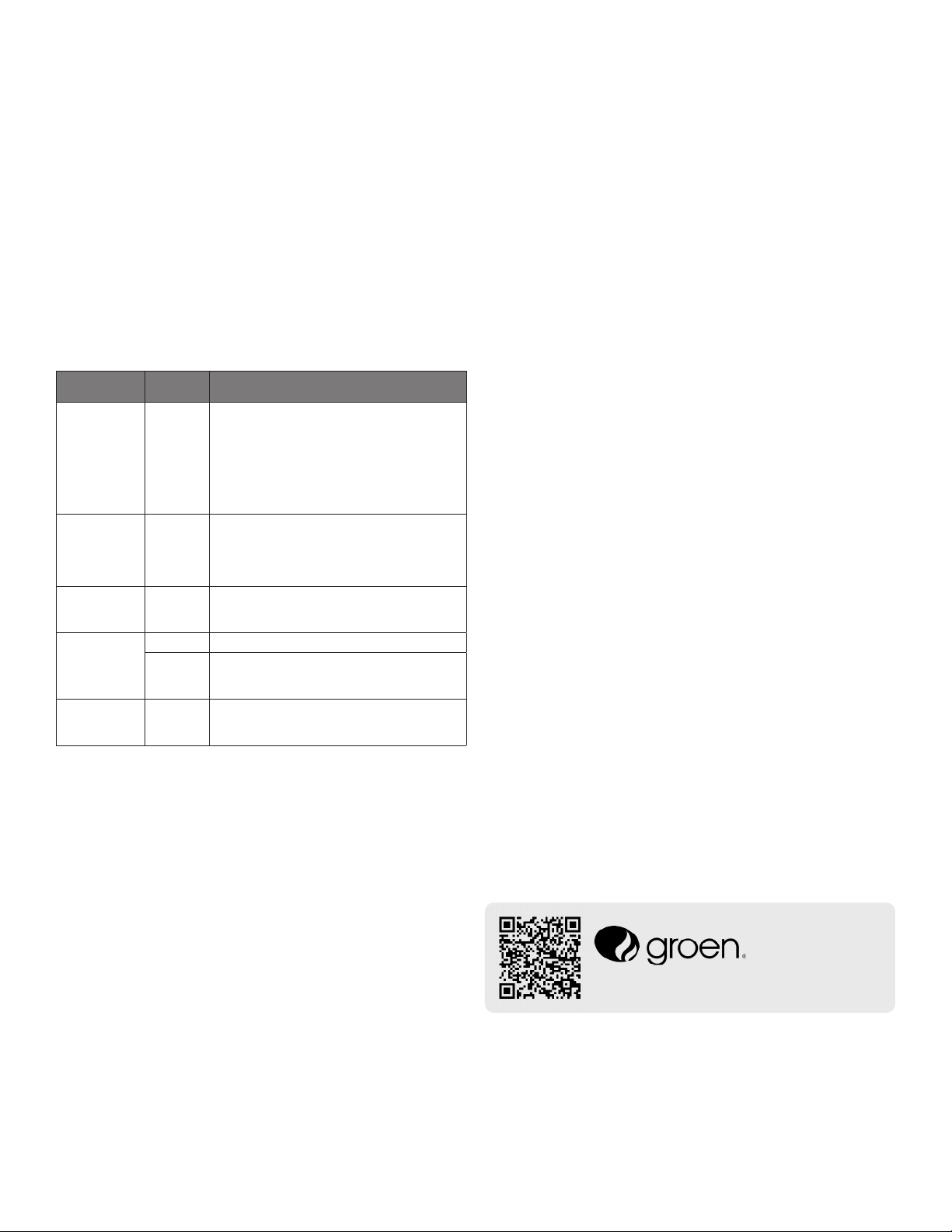
WARNING: DO NOT CONNECT THE DRAIN DIRECTLY TO A BUILDING DRAIN. BLOCKING
THE DRAIN IS HAZARDOUS.
CAUTION: DO NOT USE PLASTIC PIPE. DRAIN MUST BE RATED FOR VERY HOT WATER.
ELECTRICAL SUPPLY CONNECTION
1. Panel Removal: Open the wiring and control panel by removing the screws on
the right side panel. Slide the panel forward, and set it aside.
2. Supply Voltage: The unit must be operated at the rated nameplate voltage.
3. Phase Selection: Refer to heater schematics for wiring information.
4. Terminal Block: The terminal block for incoming power is located at the back
of the control compartment. The ground terminal is located in the wiring
compartment near the terminal block.
5.
Supply Wire:To determine the type of wire you need for the power supply, nd the
operating voltage and number of phases on the unit data plate. Refer to the table
below or to the label on the unitʼs back for correct wire size and temperature
rating. The equipment grounding wire must comply with the National Electrical
Code (NEC) requirements. The schematic on the inside of the unitʼs right side
cover gives directions for proper connection of the terminal block jumpers. The
specied wire must be used, or the unit will not meet Underwriters Laboratories
and NEC requirements. The knockout hole is sized for a ¾ inch conduit tting on
the HY-3E and for a 1 inch conduit tting on the HY-5E.
IMPORTANT - READ FIRST - IMPORTANT
WARNING: THE UNIT MUST BE INSTALLED BY PERSONNEL QUALIFIED TO WORK WITH
ELECTRICITY AND PLUMBING. IMPROPER INSTALLATION CAN CAUSE INJURY
TO PERSONNEL AND/OR DAMAGE TO THE EQUIPMENT. THE UNIT MUST BE
INSTALLED IN ACCORDANCE WITH APPLICABLE CODES.
CAUTION: SHIPPING STRAPS ARE UNDER TENSION AND CAN SNAP BACK WHEN CUT.
CAUTION: DO NOT INSTALL THE UNIT IN ANY WAY WHICH WILL BLOCK THE RIGHT SIDE
VENTS, OR WITHIN 12 INCHES OF A HEAT SOURCE SUCH AS A BRAISING PAN,
DEEP FRYER, CHARBROILER OR KETTLE.
CAUTION: LEVEL THE UNIT FRONT TO BACK, OR PITCH IT SLIGHTLY TO THE REAR, TO AVOID
DRAINAGE PROBLEMS.
WARNING: TO AVOID DAMAGE OR INJURY, FOLLOW THE WIRING DIAGRAM EXACTLY WHEN
CONNECTING A UNIT.
CAUTION: DO NOT USE PLASTIC PIPE. DRAIN MUST BE RATED FOR BOILING WATER.
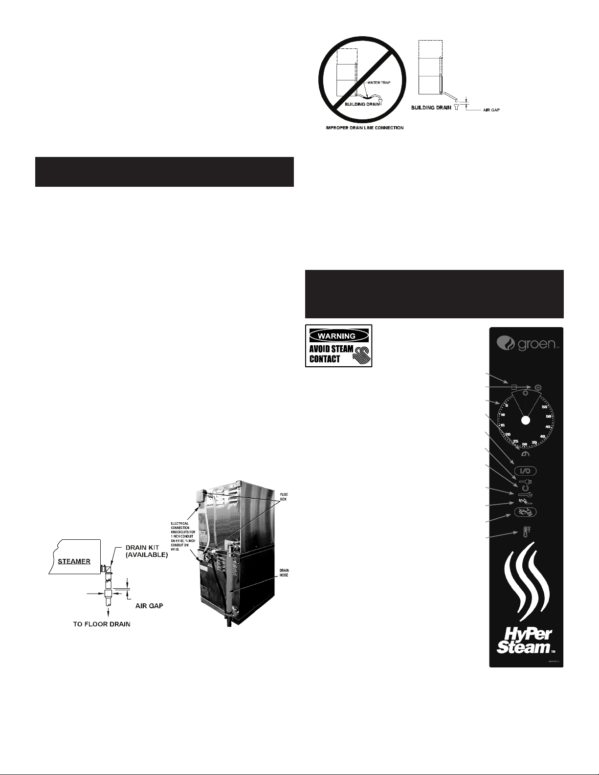
WARNING: DO NOT CONNECT THE DRAIN DIRECTLY TO A BUILDING DRAIN.
WARNING: BLOCKING THE DRAIN IS HAZARDOUS.
IMPORTANT: IMPROPER DRAIN CONNECTION WILL VOID WARRANTY.
IMPORTANT: DO NOT ALLOW ANY WATER TRAPS IN THE DRAIN LINE. A TRAP CAN CAUSE
PRESSURE TO BUILD UP INSIDE THE CAVITY DURING STEAMING, WHICH WILL
MAKE THE DOOR GASKET LEAK.
WARNING: WHEN YOU OPEN THE DOOR, STAY AWAY FROM STEAM COMING OUT OF THE
UNIT. STEAM CAN CAUSE BURNS.
WARNING: BEFORE CLEANING THE OUTSIDE OF THE STEAMER, DISCONNECT THE ELECTRIC
POWER SUPPLY. KEEP WATER AND CLEANING SOLUTIONS OUT OF CONTROLS
AND ELECTRICAL COMPONENTS. NEVER HOSE OR STEAM CLEAN ANY PART OF
THE UNIT.
WARNING: ALLOW COOKING CHAMBER TO COOL BEFORE CLEANING.
WARNING: CAREFULLY READ THE WARNINGS AND FOLLOW THE DIRECTIONS ON THE LABEL
OF EACH CLEANING AGENT. USE SAFETY GLASSES AND RUBBER GLOVES AS
RECOMMENDED BY DE-LIMING AGENT MANUFACTURER.
WARNING: DO NOT MIX DE-LIMING AGENTS (ACID) AND DE-GREASERS (ALKALI).
WARNING: DO NOT PUT HANDS OR TOOLS INTO THE COOKING CHAMBER UNTIL THE FAN HAS
STOPPED TURNING.
WARNING: DO NOT OPERATE THE UNIT UNLESS THE REMOVABLE LEFT AND RIGHT SIDE PANELS
HAVE BEEN RETURNED TO THEIR PROPER LOCATIONS.
NOTICE: DO NOT USE A CLEANING OR DE-LIMING AGENT THAT CONTAINS ANY SULFAMIC
ACID OR ANY CHLORIDE, INCLUDING HYDROCHLORIC ACID. IF THE CHLORIDE
CONTENT OF ANY PRODUCT IS UNCLEAR, CONSULT THE MANUFACTURER.
NOTICE: DO NOT USE ANY DE-GREASER THAT CONTAINS POTASSIUM HYDROXIDE OR
SODIUM HYDROXIDE OR THAT IS ALKALINE.
WARNING: USE OF ANY REPLACEMENT PARTS OTHER THAN THOSE SUPPLIED BY GROEN OR
THEIR AUTHORIZED DISTRIBUTOR VOIDS ALL WARRANTIES AND CAN RESULT IN
BODILY INJURY TO THE OPERATOR AND DAMAGE THE EQUIPMENT. SERVICE BY
OTHER THAN FACTORY AUTHORIZED PERSONNEL WILL VOID ALL WARRANTIES.
WARNING: HIGH VOLTAGE EXISTS INSIDE CONTROL COMPARTMENTS. DISCONNECT FROM
BRANCH BEFORE SERVICING. FAILURE TO DO SO CAN RESULT IN SERIOUS INJURY
OR DEATH.
FIELD WIRING TABLE - USE COPPER WIRE ONLY - INSULATION RATING THHN (90ºC)
VOLTAGE
(60 Hz
Only)
KW Field Wiring Rated Current Demand
MODEL HY-3E HY-5E HY-3E HY-5E HY-3E HY-5E
480 3
PHASE 8.1 15.5 14 AWG 12 AWG 10 Amps 18.6 Amps
240 1
PHASE 8.1 15.5 8 AWG 4 AWG 33 Amps 64.6 Amps
240 3
PHASE 8.1 15.5 10 AWG 8 AWG 20 Amps 37.3 Amps
208 1
PHASE 8.1 15.5 8 AWG 4 AWG 39 Amps 74.5 Amps
208 3
PHASE 8.1 15.5 10 AWG 6 AWG 23 Amps 43 Amps
6. Branch Circuit Protection: Each Steamer, including individual units of stacked
models, should have its own branch circuit protection and ground wire.
Current and power demands for each unit are as shown above.
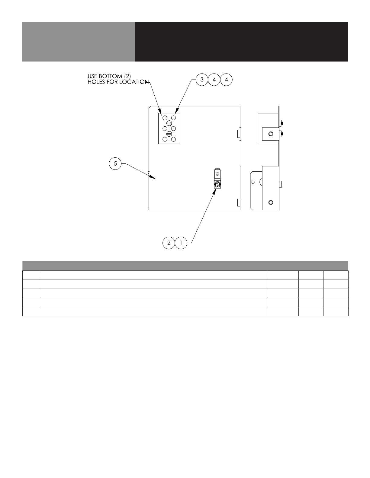
WATER CONNECTION(S)
Install a check valve to prevent back ow in the incoming cold water line, as
required by local plumbing codes. Water pressure in the line should be between
30 and 60 PSIG and must deliver a ow rate of 1.5 to 3.0 gallons per minute. If
pressure is above 60 PSIG, a pressure regulator will be needed.
A ¾ inch female NH connector (garden hose type) is used to attach the water
supply to the inlet valve. Minimum inside diameter of the water feed line is ½
inch. Use a washer in the hose connection. Do not allow the connection to leak, no
matter how slowly. The dual water standard connection, treated (softened) water
goes to the right (seen from the rear of the unit), and untreated water to the left.
Connections for both are made as shown below.
DRAIN CONNECTION
Level the steamer front to back, or pitch it slightly to the rear (maximum ¼ inch) by
adjusting the bullet feet on the stand or cabinet base.


 User manual")


 Operator service User manual")


HY-5G User manual")