6 OM-TDB(C) (C,A) (CE) INTERNATIONAL
2. Basket Insert
An optional kettle basket insert can assist in cooking water-boiled products
including eggs, potatoes, vegetables, shell fish, pasta and rice. The nylon mesh
liner must be used when cooking product smaller than the mesh size of the
basket, which is approximately 1/4” (6 mm).This includes rice and small pasta
shapes. Tips for use:
a. Allow for the water displacement of the basket and product to be cooked.
This may mean only filling the kettle half full of water. Test the basket
and product displacement with the kettle OFF, and with cold water in the
kettle.
b. Load baskets on a level, stable work surface.
c. Lift loaded baskets with both hands. Get help from another person if the
basket is too heavy for safe handling.
d. Slowly lower product into kettle.
e. When removing baskets with cooked product, lift straight up, ensuring
basket bottoms clear the kettle rim and pouring lip. Wear protective oven
mitts and protective apron.
f. Allow hot water to fully drain from product before moving basket away
from the kettle. Do not rest baskets on kettle rim or pouring lip. If baskets
are too heavy for individual to lift and safely move, get help. Remove
product immediately from basket into another container, being sure to
avoid contact with hot product and hot basket or...
g. Place baskets with food on a stable, flat surface, inside a solid steamer or
bake pan,to catch any remaining hot water draining from product.
CLEANING
WARNING: KEEP WATER AND SOLUTIONS AWAY FROM CONTROLS AND ELECTRICAL
EQUIPMENT. NEVER SPRAY THE SUPPORT HOUSING OR ELECTRICAL
CONNECTIONS.
CAUTION: MOST CLEANERS ARE HARMFUL TO THE SKIN, EYES, MUCOUS
MEMBRANES, AND CLOTHING. PRECAUTIONS SHOULD BE TAKEN. WEAR
RUBBER GLOVES, GOGGLES OR FACE SHIELD, AND PROTECTIVE CLOTHING.
READ THE WARNINGS AND FOLLOW THE DIRECTIONS ON THE LABEL OF
THE CLEANER CAREFULLY.
CAUTION: NEVER LEAVE A SANITIZER IN CONTACT WITH STAINLESS STEEL SURFACES
LONGER THAN 30 MINUTES. LONGER CONTACT CAN CAUSE CORROSION.
WARNING: AVOID DIRECT CONTACT WITH HOT SURFACES. DIRECT SKIN CONTACT
COULD RESULT IN SEVERE BURNS.
Use a brush, sponge, cloth, plastic or
rubber scraper, or plastic wool to clean.
Don’t use metal implements
or steel wool when cleaning.
OM-TD
11
Don’t scrape with tools, steel wool or other
abrasives.
Use brushes, sponges or cloth to clean your
kettles
e) Allow hot water to fully drain from
product before moving the basket away
from the kettle. Do not rest the kettle
basket on the kettle rim or pouring lip. If
the basket is too heavy for one
individual to lift and safely move, get
help from another person. Remove
product immediately from the basket into
another container, being sure to avoid
contact with hot product and hot basket
or. . .
f) Place basket with food on stable, at
surface, setting it inside a solid steamer
or bake pan, to catch any remaining hot
water which might drain from product.
Cleaning
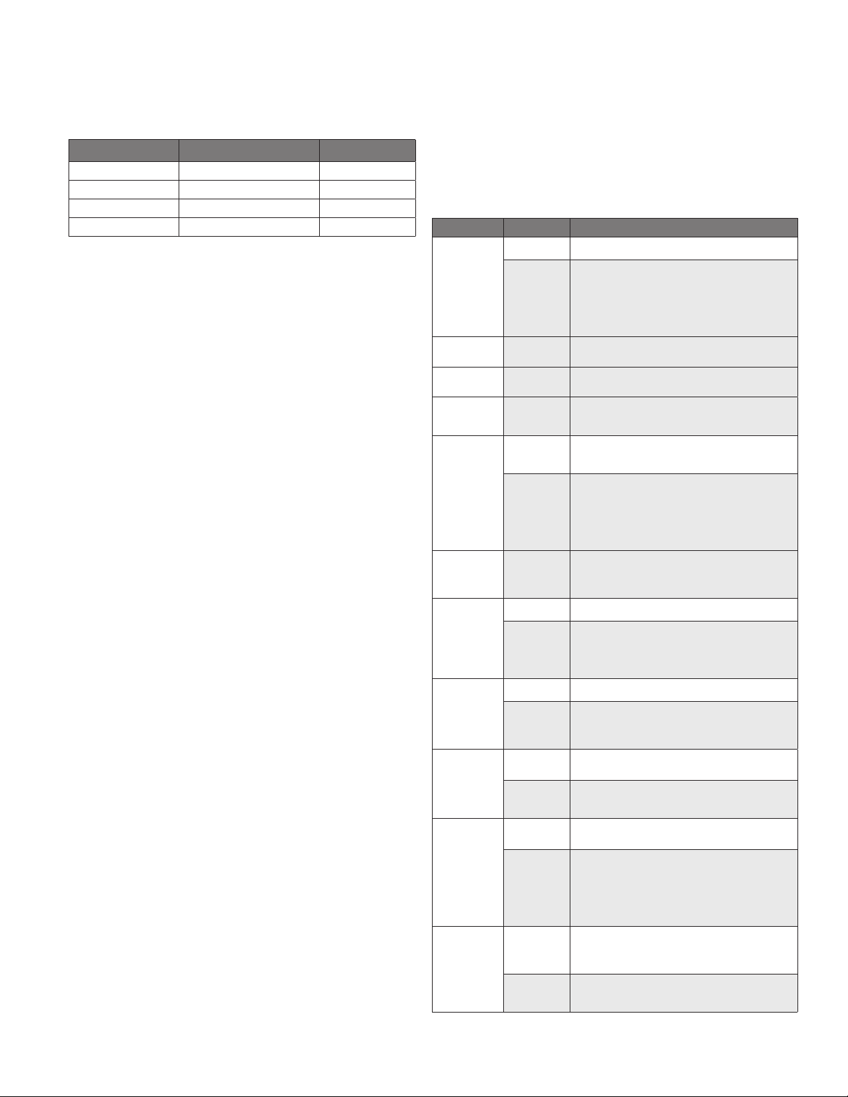
1. Suggested Tools:
a. A good cleaner.
b. Kettle brushes in good condition.
c. A good sanitizer.
d. Film remover.
CAUTION
MOST CLEANERS ARE HARMFUL TO THE
SKIN, EYES, MUCOUS MEMBRANES, AND
CLOTHING. PRECAUTIONS SHOULD BE
TAKEN. WEAR RUBBER GLOVES,
GOGGLES OR FACE SHIELD, AND
PROTECTIVE CLOTHING. READ THE
WARNI N GS AND FOLLOW T H E
DIRECTIONS ON THE LABEL OF THE
CLEANER CAREFULLY.
2. Procedure
a. Clean food-contact surfaces as soon as
possible after use. If the unit is in
continuous use, thoroughly clean and
sanitize the interior and exterior at least
once every 12 hours.
WARNING
AVOID ANY DIRECT CONTACT WITH HOT
SURFACES. DIRECT SKIN CONTACT
COULD RESULT IN SEVERE BURNS.
b. Scrape and ush out food residues. Be
careful not to scratch the kettle with
metal implements.
c. Prepare a hot solution of the detergent/
cleaning compound as instructed by the
supplier.
d. Clean the unit thoroughly, inside and
outside.
e. Rinse the kettle thoroughly with hot
water, then drain completely.
11
OM-TD
11
WEAR EYE
PROTECTION
WEAR EYE
PROTECTION
OM-TD
11
Don’t scrape with tools, steel wool or other
abrasives.
Use brushes, sponges or cloth to clean your
kettles
e) Allow hot water to fully drain from
product before moving the basket away
from the kettle. Do not rest the kettle
basket on the kettle rim or pouring lip. If
the basket is too heavy for one
individual to lift and safely move, get
help from another person. Remove
product immediately from the basket into
another container, being sure to avoid
contact with hot product and hot basket
or. . .
f) Place basket with food on stable, at
surface, setting it inside a solid steamer
or bake pan, to catch any remaining hot
water which might drain from product.
Cleaning
1. Suggested Tools:
a. A good cleaner.
b. Kettle brushes in good condition.
c. A good sanitizer.
d. Film remover.
CAUTION
MOST CLEANERS ARE HARMFUL TO THE
SKIN, EYES, MUCOUS MEMBRANES, AND
CLOTHING. PRECAUTIONS SHOULD BE
TAKEN. WEAR RUBBER GLOVES,
GOGGLES OR FACE SHIELD, AND
PROTECTIVE CLOTHING. READ THE
WARNI N GS AND FOLLOW T H E
DIRECTIONS ON THE LABEL OF THE
CLEANER CAREFULLY.
2. Procedure
a. Clean food-contact surfaces as soon as
possible after use. If the unit is in
continuous use, thoroughly clean and
sanitize the interior and exterior at least
once every 12 hours.
WARNING
AVOID ANY DIRECT CONTACT WITH HOT
SURFACES. DIRECT SKIN CONTACT
COULD RESULT IN SEVERE BURNS.
b. Scrape and ush out food residues. Be
careful not to scratch the kettle with
metal implements.
c. Prepare a hot solution of the detergent/
cleaning compound as instructed by the
supplier.
d. Clean the unit thoroughly, inside and
outside.
e. Rinse the kettle thoroughly with hot
water, then drain completely.
11
OM-TD
11
WEAR EYE
PROTECTION
WEAR EYE
PROTECTION
SUGGESTED CLEANING SUPPLIES
1. Cleaner, such as Klenzade HC-10 or HC-32 from ECOLAB, Inc. or equivalent.
2. Kettle brushes in good condition
3. Sanitizer such as Klenzade XY-12.
4. Film remover such as Klenzade LC-30.
PRECAUTIONS
Before cleaning, shut off the kettle by turning the main power switch to “OFF,” and
shut off all electric power to the unit at a remote switch, such as the circuit breaker.
PROCEDURE
1. Clean food-contact surfaces as soon as possible after use. If the unit is in
continuous use, thoroughly clean and sanitize the interior and exterior at least
once every 12 hours.
2. Scrape and flush out food residues. Be careful not to scratch the kettle with
metal implements.
3. Prepare a hot solution of the detergent/cleaning compound as instructed
by the supplier. Clean the unit thoroughly. A cloth moistened with cleaning
solution can be used to clean controls, housings, and electrical conduits.
4. Rinse the kettle and draw-off valve parts thoroughly with hot water, then drain
completely.
5. As part of the daily cleaning program, clean soiled external and internal
surfaces. Remember to check the sides of the unit and control housing,
underside of cover, etc.
6. To remove burnt on foods, use a brush, sponge, cloth, plastic or rubber scraper,
or plastic wool with the cleaning solution.To reduce effort required in washing,
let the detergent solution sit in the kettle and soak into the residue. Do NOT use
abrasive materials or metal tools that might scratch the surface. Scratches
make the surface harder to clean and provide places for bacteria to grow.
Do NOT use steel wool, which may leave particles in the surface and cause
eventual corrosion and pitting.
7. The outside of the unit may be cleaned with a warm water (100°F or less)
spray. Do not use a high pressure spray.
8. The outside of the unit may be polished with a stainless steel cleaner such as
“Zepper” from Zep Manufacturing Co.
9. When equipment needs to be sanitized, use a solution equivalent to one that
supplies 200 parts per million available chlorine. Obtain advice on sanitizing
agents from your supplier of sanitizing products.
10. It is recommended that each piece of equipment be sanitized just before use.
11. Clean the kettle thoroughly. If there is difficulty removing mineral deposits or a
film left by hard water or food residues, then use a de-liming agent, following
manufacturer directions.
12. Rinse and drain the unit thoroughly before further use.
13. If cleaning problems persist, contact your cleaning product representative for
assistance. The supplier has a trained technical staff with laboratory facilities
to serve you.
MAINTENANCE
WARNING: AVOID ANY EXPOSURE TO THE STEAM BLOWING OUT OF THE PRESSURE
RELIEF VALVE. SEVERE BURNS CAN RESULT ON EXPOSED SKIN. FAILURE
TO CHECK PRESSURE RELIEF VALVE OPERATION PERIODICALLY COULD
RESULT IN PERSONAL INJURY AND/OR DAMAGE TO EQUIPMENT.
CAUTION: KEEP GREASE AWAY FROM ELECTRICAL PARTS LOCATED NEAR THE
GEARS.
WARNING: TO AVOID INJURY, READ AND FOLLOW ALL PRECAUTIONS STATED ON THE
LABEL OF THE WATER TREATMENT COMPOUND.
WARNING: USE OF ANY REPLACEMENT PARTS OTHER THAN THOSE SUPPLIED BY
THE MANUFACTURER OR THEIR AUTHORIZED DISTRIBUTORS CAN CAUSE
INJURY TO THE OPERATOR AND DAMAGE TO THE EQUIPMENT AND WILL
VOID ALL WARRANTIES.
CAUTION: INSURE ELECTRICAL POWER IS REMOVED AND THE GAS IS TURNED OFF AT
THE SHUTOFF VALVE PRIOR TO PERFORMING ANY MAINTENANCE ON THIS
KETTLE.
WARNING: THIS KETTLE IS DESIGNED TO BE WATER RESISTANT. FAILURE TO FOLLOW
PROPER MAINTENANCE PROCEDURES MAY VOID THE WARRANTY.