Groen D User manual

1055 Mendell Davis Drive
Jackson, MS 39272
888-994-7636, fax 888-864-7636
unifiedbrands.net
This manual provides information for:
MODELS D SERIES:
D, DT, DL, DLT &
DISCONTINUED MODELS
MW/D & MW/DT Domestic
STEAM JACKETED
KETTLE
· Stainless Steel
· Direct Steam Heated
· Tilting
OPERATOR MANUAL
IMPORTANT INFORMATION, KEEP FOR OPERATOR
PART NUMBER 121007, REV. D (10/12)
THIS MANUAL MUST BE RETAINED FOR FUTURE REFERENCE.
READ, UNDERSTAND AND FOLLOW THE INSTRUCTIONS AND
WARNINGS CONTAINED IN THIS MANUAL.
FOR YOUR SAFETY
Do not store or use gasoline or other flammable vapors
and liquids in the vicinity of this or any other appliance.
POST IN A PROMINENT LOCATION
Instructions to be followed in the event user smells gas.
This information shall be obtained by consulting your
local gas supplier. As a minimum, turn off the gas and
call your gas company and your authorized service agent.
Evacuate all personnel from the area.
WARNING
Improper installation, adjustment, alteration, service or
maintenance can cause property damage, injury or death.
Readtheinstallation,operatingandmaintenanceinstructions
thoroughly before installing or servicing this equipment.
NOTIFY CARRIER OF DAMAGE AT ONCE
It is the responsibility of the consignee to inspect the container upon receipt of
same and to determine the possibility of any damage, including concealed dam-
age. Unied Brands suggests that if you are suspicious of damage to make a
notation on the delivery receipt. It will be the responsibility of the consignee to le
a claim with the carrier. We recommend that you do so at once.
Manufacture Service/Questions 888-994-7636.
Information contained in this document is known to be current and accurate at the time
of printing/creation. Unified Brands recommends referencing our product line websites,
unifiedbrands.net, for the most updated product information and specifications.

2 OM-D
IMPORTANT - READ FIRST - IMPORTANT
CAUTION: BE SURE ALL OPERATORS READ, UNDERSTAND AND FOLLOW THE OPERATING INSTRUCTIONS,
CAUTIONS, AND SAFETY INSTRUCTIONS CONTAINED IN THIS MANUAL.
WARNING: THIS UNIT IS INTENDED FOR USE IN THE COMMERCIAL HEATING, COOKING AND HOLDING OF
WATER AND FOOD PRODUCTS, PER THE INSTRUCTIONS CONTAINED IN THIS MANUAL. ANY
OTHER USE COULD RESULT IN SERIOUS PERSONAL INJURY OR DAMAGE TO THE EQUIPMENT
AND WILL VOID WARRANTY.
CAUTION: SHIPPING STRAPS ARE UNDER TENSION AND CAN SNAP BACK WHEN CUT.
CAUTION: UNIT WEIGHS 190 TO 270 LBS (85 TO 125 KG). FOR SAFE HANDLING, INSTALLER SHOULD
GET HELP AS NEEDED, OR USE MATERIALS HANDLING EQUIPMENT (E.G., FORK LIFT, DOLLY
OR PALLET JACK) TO REMOVE THE UNIT FROM THE SKID AND MOVE IT TO THE PLACE OF
INSTALLATION.
WARNING: KETTLES MUST BE INSTALLED BY PERSONNEL QUALIFIED TO WORK WITH PLUMBING.
IMPROPER INSTALLATION CAN RESULT IN INJURY TO PERSONNEL AND/OR DAMAGE TO
EQUIPMENT.
WARNING: AVOID ANY EXPOSURE TO ESCAPING STEAM. STEAM CAN CAUSE SEVERE BURNS.
WARNING: TAKE EXTREME CARE TO KEEP HOT CONTENTS FROM SPILLING OR SPLASHING ON ANYONE.
DO NOT STAND DIRECTLY IN FRONT OF KETTLE BODIES WHEN THEY ARE BEING TILTED.
WARNING: AVOID ALL DIRECT CONTACT WITH HOT EQUIPMENT SURFACES. DIRECT SKIN CONTACT COULD
RESULT IN SEVERE BURNS.
WARNING: AVOID ALL DIRECT CONTACT WITH HOT FOOD OR WATER IN KETTLES. DIRECT CONTACT
COULD RESULT IN SEVERE BURNS.
CAUTION: DO NOT OVER FILL THE KETTLE WHEN COOKING, HOLDING OR CLEANING. KEEP LIQUIDS
A MINIMUM OF 2-3” (5-8 CM) BELOW THE KETTLE BODY RIM TO ALLOW CLEARANCE FOR
STIRRING, BOILING AND SAFE PRODUCT TRANSFER.
WARNING: TAKE SPECIAL CARE TO AVOID CONTACT WITH HOT KETTLE BODY OR HOT PRODUCT WHEN
ADDING INGREDIENTS, STIRRING OR TRANSFERRING PRODUCT TO ANOTHER CONTAINER.
WARNING: WHEN TILTING KETTLE FOR PRODUCT TRANSFER:
1) WEAR PROTECTIVE OVEN MITT AND PROTECTIVE APRON.
2) USE CONTAINER DEEP ENOUGH TO CONTAIN AND MINIMIZE PRODUCT SPLASHING.
3) PLACE CONTAINER ON STABLE, FLAT SURFACE, AS CLOSE TO KETTLE AS POSSIBLE.
4) STAND TO LEFT OR RIGHT SIDE OF KETTLE (DEPENDING ON TILTING HANDLE PLACEMENT)
WHILE POURING. DO NOT STAND DIRECTLY IN POUR PATH OF HOT CONTENTS.
5) POUR SLOWLY, MAINTAIN CONTROL OF KETTLE BODY HANDLE AT ALL TIMES, AND
RETURN KETTLE BODY TO UPRIGHT POSITION AFTER CONTAINER IS FILLED OR TRANSFER IS
COMPLETE.
6) DO NOT OVERFILL CONTAINER. AVOID DIRECT SKIN CONTACT WITH HOT CONTAINER AND ITS
CONTENTS.
CAUTION: KEEP FLOORS IN FRONT OF KETTLE WORK AREA CLEAN AND DRY. IF SPILLS OCCUR, CLEAN
IMMEDIATELY, TO AVOID SLIPS OR FALLS.
WARNING: FAILURE TO CHECK SAFETY VALVE OPERATION PERIODICALLY COULD RESULT IN PERSONAL
INJURY AND/OR DAMAGE TO EQUIPMENT.
WARNING: WHEN TESTING, AVOID ANY EXPOSURE TO THE STEAM BLOWING OUT OF THE SAFETY VALVE.
DIRECT CONTACT COULD RESULT IN SEVERE BURNS.

OM-D 3
IMPORTANT - READ FIRST - IMPORTANT
WARNING: TO AVOID INJURY, READ AND FOLLOW ALL PRECAUTIONS STATED ON THE LABEL OF THE
WATER TREATMENT COMPOUND.
CAUTION: MOST CLEANERS ARE HARMFUL TO THE SKIN, EYES, MUCOUS MEMBRANES AND CLOTHING.
PRECAUTIONS SHOULD BE TAKEN. WEAR RUBBER GLOVES, GOGGLES OR FACE SHIELD AND
PROTECTIVE CLOTHING. CAREFULLY READ THE WARNINGS AND FOLLOW THE DIRECTIONS ON
THE LABEL OF THE CLEANER TO BE USED.
CAUTION: USE OF ANY REPLACEMENT PARTS OTHER THAN THOSE SUPPLIED BY GROEN OR ITS
AUTHORIZED DISTRIBUTORS CAN CAUSE OPERATOR INJURY AND DAMAGE TO THE
EQUIPMENT, AND WILL VOID ALL WARRANTIES.
IMPORTANT: SERVICE PERFORMED BY OTHER THAN FACTORY AUTHORIZED PERSONNEL WILL VOID
WARRANTIES.

4 OM-D
Important Operator Warnings .....................................................page 2-3
References ................................................................................... page 4
Equipment Description ................................................................. page 5
Inspection & Unpacking .............................................................. page 6
Installation ..................................................................................... page 7
Initial Start-Up .............................................................................. page 8
Operation ..................................................................................... page 9
Cleaning ................................................................................. page 10-11
Maintenance ............................................................................ page 12
Sequence of Operation .............................................................. page 13
Troubleshooting .......................................................................... page 14
Parts List ................................................................................. page 15-18
Bucket Steam Trap ....................................................................... page 19
Installation Diagram Chair for Wall Mount Kettles ........................ page 20
Service Log ................................................................................. page 21
KLENZADE SALES CENTER
ECOLAB. Inc.
370 Wabasha
St. Paul, Minnesota 55102
800/352-5326 or 612/293-2233
NSF INTERNATIONAL
798 N. Dixboro Rd.
P.O. Box 130140
Ann Arbor, Michigan 48113-0140
ZEP MANUFACTURING CO.
1310-T Seaboard Industrial Blvd.
Atlanta, Georgia 30318
Table of Contents
References

OM-D 5
The Groen D Series are deep type, tilting kettles with direct steam-heated 2/3 jackets.
The stainless steel kettles have welded, reinforced rims and buttery shaped pouring
lips. The liner and pouring lip of all kettles are 316 stainless steel. They are ASME
shop-inspected, and are registered with the National Board. The kettles have a 180
emery grit interior finish and a bright semi-deluxe exterior finish.
Every unit requires a remote steam source. The steam supply is controlled by an
inlet valve, and enters the jacket through one trunnion directly into the jacket. Steam
pressure forces condensate out a dip tube through the other trunnion. Both steam and
condensate lines are concealed within the support structures of the various models.
The table to the left shows the standard kettle sizes for each model.
These kettles operate safely and efficiently at various steam pressures above five
PSI, with upper pressure limits assured by the provided safety valve. Operation also
requires a globe valve on the steam inlet and a strainer, steam trap, and check valve
on the condensate outlet. These may be ordered from Groen as optional equipment.
D Series kettles are emptied by tilting, but optional tangent draw-os are available. The
standard draw-off is two inch outer diameter stainless steel, with compression disc
valve and a removable stainless steel strainer that has 1/4 inch perforations. Strainers
with 1/8 inch or no perforations are also available. The table on the left shows the
sizes of draw-offs which can be furnished with each model. When equipped with a
tangent draw-off the designation “T” is added to the model designation.
The kettles in this series employ a worm and gear tilting mechanism, which is
completely enclosed.
D Series kettles are mounted in three ways. Model D is suspended in a stainless steel
yoke on a pedestal base. The outer circumference of the base is flanged down for
proper sealing to the floor. Model DL is supported by a tubular, stainless steel tri-leg
frame with adjustable floor flanges. The discontinued wall-mounted model MW/D had
a supporting frame enclosed in a stainless steel, drip-proof housing. The frame hung
on an in-wall carrier which was purchased as an option.
Other options include:
1. No. 31 lift-off cover (for kettles smaller than 60 gallons)
2. No. 51 cover with counter-balancing actuator (for 40 gallon and larger kettles)
3. Fill faucets with swing spout
4. Gallon Master water meter
5. TRI-BC basket cooking system
6. Kettle brush kit
7. Operating pressures up to 90 PSIG
Equipment Description
STANDARD CAPACITIES, GALLONS
Model 20 40 60 80 100
D•••
DT • •
DL, DLT ••••
MW/D, MW/DT •••• •
OPTIONAL DRAW-OFFS AVAILABLE*
Model 1-1/2” 2” 3”
DT (20 or 40 Gallon) • •
DLT (All Sizes) • •
MW/DT (All Sizes) • • •
*2” or 3” ONLY provided
on current production.

6 OM-D
Inspection & Unpacking
CAUTION
SHIPPING STRAPS ARE UNDER TENSION
AND CAN SNAP BACK WHEN CUT. AVOID
NAILS AND SPLINTERS WHEN
REMOVING KETTLES FROM WOODEN
CRATES. WEAR SAFETY GLASSES.
The kettle will arrive completely assembled and wrapped in protective plastic,
strapped and bolted on a heavy skid, enclosed in a crate. Immediately on receipt
remove the box and plastic wrap, and inspect the unit for damage. Report any damage
or an incorrect shipment to the delivery agent.
Write down the model number, serial number and installation date, and keep this
information for future reference. Space for these entries is provided at the top of the
Service Log in the back of this manual.
When installation is to begin, cut the straps holding the unit on the skid. Lift the unit
straight up off of the skid.
CAUTION
UNIT WEIGHS 215 TO 295 LBS (98 TO 134
KG). FOR SAFE HANDLING, INSTALLER
SHOULD GET HELP AS NEEDED, OR USE
MATERIALS HANDLING EQUIPMENT (e.g.,
FORK LIFT, DOLLY OR PALLET JACK) TO
REMOVE THE UNIT FROM THE SKID AND
PLACE IT FOR INSTALLATION.

OM-D 7
1. Installation under a ventilation hood is recommended. Consult local codes.
2. Install and anchor the kettle on a level surface.
3. If the steam supply pressure is greater than the maximum working pressure
stamped on the nameplate, you must install a pressure reducing valve in the steam
supply line near the kettle.
4. Connect the steam supply line to the steam inlet fitting. Include a steam control
valve and an appropriate safety valve. To obtain the full heating capability of the
kettle, the steam supply line must be as large as the steam inlet fitting.
5. The safety valve is preset to relieve jacket pressure that exceeds its rated limit. Do
not try to adjust the valve setting, and do not allow the valve outlet or lever to be
blocked.
6. Connect the kettle condensate return line to the boiler return line, or to a drain.
A suitable steam trap, strainer, and check valve must be installed on the left side
kettle trunnion (viewed from the front). (See piping diagram, Page 19).
7. Any mechanical change must be approved by the Groen Food Service Engineering
Department.
FLOOR MOUNTED MODELS ONLY:
1. Install the unit on a level surface. Ensure that there is adequate clearance at the
sides and rear, as required by the specification drawings. Anchor the pedestal or
legs securely to the floor.
2. Apply a continuous bead of clear silicone sealant (No. 732 or equivalent) to the
junction between the pedestal or leg flange and the surface, as shown in the
illustration at left. Fill all cracks and crevices, and wipe excess away.
COLD WATER COOLING OPTION: See image at left.
DISCONTINUED WALL MOUNTED MODELS ONLY:
1. Install a “chair carrier” in the wall to which the unit will be attached, following the
instructions pertaining to anchoring and location. See diagram on page 20.
2. Stub in the steam supply line and condensate return line so that they will be
aligned with the appropriate fittings when the unit is mounted.
3. Mount the unit on the protruding studs of the chair carrier.
4. Apply a continuous bead of clear silicone sealant (No. 732 or equivalent) to the
junction between the frame housing and the wall. Fill all cracks and crevices, and
wipe away the excess.
Installation
WARNING
THIS UNIT MUST BE INSTALLED BY
PERSONNEL QUALIFIED TO WORK WITH
PLUMBING. IMPROPER INSTALLATION CAN
CAUSE INJURY TO PERSONNEL AND/OR
DAMAGE TO EQUIPMENT.
For proper sanitation, continuous seal is
required between pedestals or flanges
and the mounting surface.

8 OM-D
Now that the kettle has been installed, you should test it to ensure that it is operating
correctly.
. DIRECT SKIN CONTACT
1. Remove all literature and packing materials from inside and outside of the unit.
Clean out any material that might clog the tangent draw-off valve, if present.
2. Pour a small amount of water into the kettle.
3. Open the steam inlet valve.
4. When the water begins to boil, inspect all of the fittings to ensure that there are no
leaks.
5. Check the safety valve by lifting its lever far enough to let steam escape. Then let it
snap back into place to reseat the valve so that it will not leak.
6. Shut down the unit by closing the steam inlet valve.
7. Operate the tilting mechanism and draw-off valve to confirm that they function
through the whole range of normal operation.
If the unit functions as described above, it is ready for use. If the unit does not function
as intended, contact your local Groen Certified Service Agency.
Initial Start-Up
IMPORTANT
BE SURE ALL OPERATORS READ,
UNDERSTAND AND FOLLOW THE
OPERATING INSTRUCTIONS, CAUTIONS
AND SAFETY INSTRUCTIONS CONTAINED
IN THIS MANUAL.
WARNING
AVOID ANY EXPOSURE TO ESCAPING
STEAM, WHICH CAN CAUSE SEVERE BURNS.

OM-D 9
Operation
Before operating a cold kettle, open the petcock at the bottom of the jacket to drain
any water left by condensing steam. Close the petcock before you open the steam
inlet valve. Draining this water decreases the “hammering” you hear when steam
enters a cold jacket.
To heat the kettle, open the steam inlet valve. Adjusting the inlet valve allows the
operator to control the heating rate. Opening the valve more allows steam to flow into
the jacket faster, and thereby heats the product faster.
The kettle operates efficiently with steam pressures from five PSI to the maximum
working pressure for which the kettle was designed. The maximum allowable
pressure is stamped on the kettle nameplate. It is 25 PSI for standard units.
Once a day, while there is still steam pressure in the jacket, bleed off any entrapped
air and double check the operation of the safety valve. Pull out on its chain, or lift the
lever far enough to let steam escape. Then let it snap back into place to reseat the
valve so that it will not leak.
TILTING THE KETTLE:
To transfer product or empty the kettle: turn the handwheel counterclockwise. The
kettle will hold its position when you stop turning the wheel. If the tilting mechanism
seems to be locked, do not use force to free the kettle. Call for assistance from your
Groen Certified Service Agency, or refer to the Troubleshooting section of this manual.
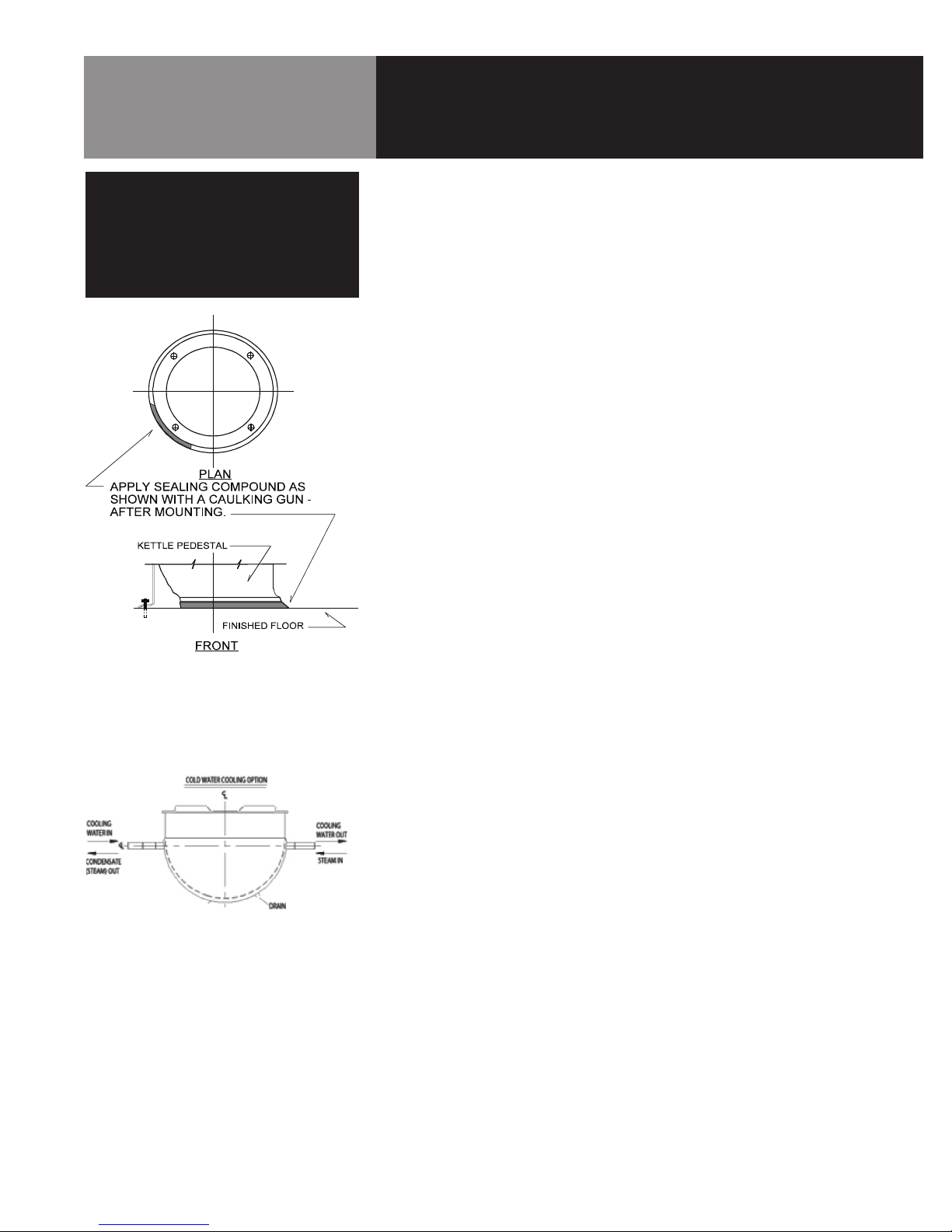
OPTIONAL COLD WATER COOLING: (Reference Typical Piping Arrangement Drawings)
Sequence of Operation for Heating
1. Close Water Inlet Valve, Kettle Drain Valve, and Water Outlet Valve
2. Open Condensate Outlet Valve
3. Open Steam Inlet Valve
Sequence of Operation for Cooling
1. Close Steam Inlet Valve and Condensate Outlet Valve
2. Open Water Outlet Valve
3. Open Water Inlet Valve
Sequence of Operation for Heating after Cooling
1. Close Water Inlet Valve and Water Outlet Valve
2. Open Kettle Drain Valve until jacket is empty
3. Open Condensate Outlet Valve
4. Open Steam Inlet Valve
WARNING
AVOID EXPOSURE TO ESCAPING STEAM,
WHICH CAN CAUSE SEVERE BURNS.
CAUTION
DO NOT OVERFILL THE KETTLE WHEN
COOKING, HOLDING OR CLEANING. KEEP
LIQUIDS AT LEAST 2-3” (5-8 cm) BELOW
THE KETTLE BODY RIM TO ALLOW
CLEARANCE FOR STIRRING, BOILING
PRODUCT AND SAFE TRANSFER.
WARNING
WHEN TILTING KETTLE FOR PRODUCT
FOR PRODUCT TRANSFER:
1) WEAR PROTECTIVE OVEN MITT AND
PROTECTIVE APRON.
2) USE CONTAINER DEEP ENOUGH TO
CONTAIN AND MINIMIZE PRODUCT
SPLASHING.
3) PLACE CONTAINER ON STABLE, FLAT
SURFACE, AS CLOSE TO KETTLE AS
POSSIBLE.
4) STAND TO LEFT OR RIGHT SIDE OF
KETTLE WHILE POURING – NOT
DIRECTLY IN POUR PATH OF HOT
CONTENTS.
5) POUR SLOWLY, MAINTAIN CONTROL
OF KETTLE AT ALL TIMES, AND
RETURN KETTLE BODY TO UPRIGHT
POSITION AFTER CONTAINER IS
FILLED OR TRANSFER IS COMPLETE.
6) DO NOT OVERFILL CONTAINER. AVOID
DIRECT SKIN CONTACT WITH HOT
CONTAINER AND ITS CONTENTS.
WARNING
AVOID ALL DIRECT CONTACT WITH
HOT FOOD OR WATER IN THE KETTLE.
DIRECT CONTACT COULD RESULT IN
SEVERE BURNS. TAKE CARE TO AVOID
CONTACT WITH HOT KETTLE BODY OR HOT
PRODUCT. WHEN ADDING INGREDIENTS,
STIRRING OR TRANSFERRING PRODUCT
TO ANOTHER CONTAINER.

10 OM-D
Cleaning
A. Suggested Cleaning Supplies
1. A high quality detergent and sanitizer, or a combination cleaning-
sanitizing agent.
2. Kettle brushes in good condition.
3. Brush suitable for cleaning the tangent draw-off port (if kettle has optional
tangent).
4. Use a good sanitizer
5. Film remover
B. Procedure
1. Clean food-contact surfaces as soon as possible after use. If the unit is in con-
tinuous use, thoroughly clean and sanitize the interior and exterior at least once
every 12 hours.
2. Scrape and flush out food residues. Be careful not to scratch the kettle with
metal implements.
3. Prepare a hot solution of the detergent/ cleaning compound as instructed by the
supplier.
4. Clean the unit thoroughly, inside and outside.
5. Rinse the kettle thoroughly with hot water, then drain completely.
6. As part of the daily cleaning program, clean soiled external and internal sur-
faces.
7. To remove stuck materials, use a brush, sponge, cloth, plastic or rubber scraper,
or plastic wool with the cleaning solution. To reduce effort required in wash-
ing, let the detergent solution sit in the kettle and soak into the residue. Do not
use abrasive materials or metal tools that might scratch the surface. Scratches
make the surface harder to clean and provide places for bacteria to grow. Do
not use steel wool, which may leave particles in the surface and cause eventual
corrosion and pitting.
8. The outside of the unit maybe polished with a stainless steel cleaner such as
“Zepper” from Zep Manufacturing Co.
9. When equipment needs to be sanitized, use a solution equivalent to one that
supplies 200 parts per million available chlorine. Obtain advice on sanitiz-
ing agents from your supplier of sanitizing products. Following the supplier’s
instructions, apply the agent after the unit has been cleaned and drained. Drain
and thoroughly rinse off the sanitizer.
10.It is recommended that each piece of equipment be sanitized just before use.
11.If there is difficulty removing mineral deposits or a film left by hard water or
food residues, clean the kettle thoroughly and use a deliming agent, like Groen
Delimer/Descaler (Part Number 114800), in accordance with the manufacturer’s
directions. Rinse and drain the unit thoroughly before further use.
CAUTION
NEVER LEAVE A CHLORINE SANITIZER
IN CONTACT WITH STAINLESS STEEL
SURFACES FOR LONGER THAN 30
MINUTES. LONGER CONTACT CAN
CAUSE CORROSION.
CAUTION
MOST CLEANERS ARE HARMFUL TO THE
SKIN, EYES, MUCOUS MEMBRANES AND
CLOTHING. PRECAUTIONS SHOULD BE
TAKEN TO WEAR RUBBER GLOVES,
GOGGLES OR FACE SHIELD AND
PROTECTIVE CLOTHING. CAREFULLY
READ THE WARNINGS AND FOLLOW
LABEL DIRECTIONS.

OM-D 11
Cleaning
CAUTION
NEVER LEAVE A CHLORINE SANITIZER
IN CONTACT WITH STAINLESS STEEL
SURFACES FOR LONGER THAN 30
MINUTES. LONGER CONTACT CAN
CAUSE CORROSION.
Use a brush, sponge, cloth, plastic or
rubber scraper, or plastic wool to clean.
Don’t use metal implements
or steel wool when cleaning.
12. If cleaning problems persist, contact your cleaning product representative for
assistance. The supplier has a trained technical staff with laboratory facilities
to serve you.
13. If your unit is equipped with a tangent draw-off valve, disassemble it and clean
the draw-off port and each valve part with a brush.
NOTICE: DO NOT MIX THE PARTS OF DIFFERENT DRAW-OFF ASSEMBLIES WHEN
CLEANING. THE PARTS ARE NOT INTERCHANGEABLE.

12 OM-D
Maintenance
NOTICE: Contact an authorized representative when repairs are required.
PERIODIC MAINTENANCE
A Maintenance & Service Log is provided at the back of this manual with the warranty
information. Each time maintenance is performed on your Groen kettle, enter the date on
which the work was done, what was done, and who did it. File the log with the warranty.
Periodic inspection will minimize equipment down time and increase the efficiency of
operation. The following points should be checked:
1. Once a day, with pressure in the jacket, check the operation of the safety valve. Lift
the lever of the safety valve until steam is released. Then release the lever and let the
valve snap shut. If the lever does not activate, or there is no evidence of discharge, or
the valve leaks, immediately discontinue use of the kettle and contact a qualified Groen
service representative.
2. At least once every 90 days, inspect fittings and valves for signs of damage or wear.
Regularly examine trunnion packings and valve seats for wear, and replace them when
necessary.
NOTE: Service performed by other than factoryauthorized personnel will void all
warranties.
3. Lubricate trunnions and gears with a good grade of high temperature grease. Grease
trunnions at least once every 60 days, and grease gears when inspection shows that
they are dry.
4. If the kettle cover has an actuator, lubricate it every 90 days.
NOTE: Use only Calcium Complex Nr. 2 Grease, which is available from Groen (Part No.
093703).
WARNING
WHEN USING THE EQUIPMENT OR
TESTING, AVOID ANY EXPOSURE TO THE
STEAM BLOWING OUT OF THE SAFETY
VALVE. SEVERE BURNS CAN RESULT
ON EXPOSED SKIN. FAILURE TO CHECK
SAFETY VALVE OPERATION PERIODICALLY
COULD RESULT IN PERSONAL INJURY
AND/OR DAMAGE TO EQUIPMENT.
CAUTION
USE OF ANY REPLACEMENT PARTS
OTHER THAN THOSE SUPPLIED BY GROEN
OR AN AUTHORIZED SUPPLIER WILL VOID
ALL WARRANTIES AND COULD INJURE
THE OPERATOR OR DAMAGE THE
EQUIPMENT.

OM-D 13
Sequence of Operation
The following “action-reaction” outline is provided to help the user understand the
function of the equipment.
When the steam inlet valve is opened, steam flows into the jacket at a pressure
determined by the boiler system or by the pressure reducing valve that serves the
kettle.
In the jacket, steam transfers heat to the kettle as it condenses into water. The steam
trap allows condensate (water) to leave the jacket, while it holds steam in. When the
steam is shut off, condensation produces a vacuum in the jacket, but the check valve
in the condensate return line keeps water from flowing back into the jacket.

14 OM-D
Troubleshooting
Your Groen kettle will operate smoothly and efficiently if properly maintained. However, the following is a list of checks to make in
the event of a problem. If the actions suggested do not solve the problem, call your qualified Groen Service Representative. For the
phone number of the nearest agency, call your area Groen representative or the Groen Parts and Service Department. If an item on
the list is followed by an X, the work should be done by a qualified service representative.
WARNING
USE OF ANY REPLACEMENT PARTS OTHER THAN THOSE SUPPLIED BY GROEN OR THEIR AUTHORIZED DISTRIBUTORS CAN
CAUSE INJURY TO THE OPERATOR AND DAMAGE TO THE EQUIPMENT AND WILL VOID ALL WARRANTIES.
TO AVOID INJURY FROM SPLASHING OR SPILLING HOT CONTENTS, EMPTY THE KETTLE THROUGH
THE DRAW-OFF OR BY BAILING BEFORE ANY WORK IS DONE ON THE TILTING MECHANISM.
SYMPTOM WHO WHAT TO CHECK
X indicates items which must be performed by an authorized technician.
Kettle will not heat. User a. That the steam inlet valve is open.
b. That the steam supply line is turned on.
c. That the condensate return valve is open.
d. That the boiler is operating properly. Steam should be supplied at a
pressure greater than five PSI.
Auth Service
Rep Only
e. Steam supply line for blockage.X
f. Condensate return line for blockage.X
g. Steam trap operation.X
Safety valve leaks a
small amount of steam.
User a. For contamination that prevents seating the valve. With substantial
pressure in the jacket, lift the valve lever briefly all the way up, to blow
the valve clean then let it snap back down to seat the valve.
Auth Service
Rep Only
b. Safety valve for defects. Defective valve MUST be replaced with an
identical valve.X
Safety valve leaks a
large amount of steam.
Auth Service
Rep Only
a. Steam supply pressure.X
b. Safety valve for defects. Defective valve MUST be replaced with an
identical valve.X
Pipe fitting leaks. User a. Is the fitting tight?
Auth Service
Rep Only
b. If the leak is at a trunnion, and tightening the packing gland does not
stop the leak, replace the packing. X
Kettle is hard to tilt. Auth Service
Rep Only
a. Tilting gear and worm for the presence of any contamination and for
proper alignment and lubrication.X
Kettle makes a banging
noise when steam is
turned on.
User Drain water from the jacket by opening the petcock at the bottom of the
kettle before admitting steam into the jacket. Close the petcock before
opening the steam valve.

OM-D 15
Parts List
Key Description Part No.
1 GEAR, WORM - D-20-40-60-80 012022
2 STEAM GLAND - D-20-40-60-80 012120
3PACKING, 10 RING - D-20-40-
60-80 114824
4 NUT, PACKING - D-20-40-60-80 012122
5ENCLOS. TILT MECH. D-20-40-
60-80 139043
6 GREASE FITTING, 90 DEG. 012195
7CARRIER ASSY GEAR D-20-40-
60-80 137880
8
SAFETY VALVE (CAUTION: PRESSURE AND
FLOW RATE OF REPLACEMENT VALVE MUST
BE THE SAME AS ORIGINALLY PROVIDED.)
- 3/4” SAFETY VALVE (50 PSIG) 005587
- 1/2” SAFETY VALVE (50 PSIG) 097005
9 TEE, CHROME PLATED, 3/4 NPT 012075
10 LOCKWASHER, 3/8” 005618
11 SCREW CAP HEX 3/8-16 X 3/4 005611
12 BEARING, ROLLER 002790
13 WORM 12026
14 SHAFT 003129
15 HANDWHEEL WITH HANDLE 139152
16 HANDWHEEL SHAFT 003130
17 COLLAR 137246
18 GREASE FITTING, 45 DEG 012099
19 CASTING TRUNNION RACE- 20-
40-60-80 012113
20 DRAW-OFF VALVE, 2” (COMPLETE) 009046
- DRAW-OFF VALVE, 3” (COMPLETE) 012262
- HANDLE FOR 2” TDO VALVE 009029
- HANDLE FOR 3” TDO VALVE 012209
- STEM FOR 2” VALVE 009048
- STEM FOR 3” VALVE 001908
- WING NUT FOR 2” VALVES 009028
- BONNET FOR 2” 009047
- BONNET FOR 3” 003925
- HEX NUT FOR 2” 009354
- HEX NUT FOR 3” 003927
21 PETCOCK, JACKET DRAIN 012070
22 STAND ASSEMBLY (CALL GROEN FOR PART NO.)

16 OM-D
Parts List
Key Description Part No.
1 GEAR, WORM - D-10 -20 -30 012023
2 GEAR, WORM - D-40 -60 -80 012022
3 STEAM GLAND - D-10 -20 -30 012227
4 STEAM GLAND - D-40 -60 -80 012120
5 PACKING, 6 RING - D-10 -20 -30 012230
6 PACKING, 6 RING - D-40 -60 -80 114824
7 NUT, PACKING - D-10 -20 -30 012228
8 NUT, PACKING - D-40 -60 -80 012122
9 ENCLOS. TILT MECH. D-10 -20 -30 014075
10 ENCLOS.TILT MECH. D-40 -60 -80 014076
11 GREASE FITTING, 90 DEG. 012195
12 CARRIER ASSY, GEAR D-10 -20 -30 014077
13 CARRIER ASSY GEAR D-40 -60 -80 014079
14
SAFETY VALVE (CAUTION: PRESSURE AND
OW RATE OF REPLACEMENT VALVE MUST BE
THE SAME AS ORIGINALLY PROVIDED)
- ¾” SAFETY VALVE 005587
- ½” SAFETY VALVE 097005
15 TEE, CHROME PLATED, ¾ NPT 012075
16
LOCKWASHER, 3/8”
005618
17 SCREW CAP HEX 3/8-16 X 3/4 005611
18 BEARING, ROLLER 002790
19 WORM 012026
20 SHAFT 003129
21 HANDWHEEL WITH HANDLE 012061
22 HANDWHEEL & SHAFT
(COMPLETE) 003130
23 GREASE FITTING, 45 DEG 012099
24
CASTING TRUNNION RACE- D-10 -20 -30
012109
25
CASTING TRUNNION RACE - D-40 -60 -80
012113
26 DRAW-O VALVE, DAIRY 1½”
(COMPLETE) 009000
-DRAW-O VALVE, DAIRY, 2”
(COMPLETE) 009046
-DRAW-O VALVE, DAIRY, 3”
(COMPLETE) 012262
-HANDLE FOR 1½” OR 2” DAIRY
VALVE 009029
- HANDLE FOR 3” DAIRY VALVE 012209
- STEM FOR 1½” VALVE 009027
- STEM FOR 2” VALVE 009048
- STEM FOR 3” VALVE 001908
- WING NUT (WITH 001908) -
-WING NUT FOR 1½” AND 2”
VALVES 009028
-DRAW-O VALVE, PLUG, NEW
STYLE, 1½” 009737
-DRAW-O VALVE, PLUG, OLD
STYLE, 1½ 009734
-DRAW-O VALVE, PLUG, OLD
STYLE, 2” 009735
27 PETCOCK, JACKET DRAIN 012070
- BONNET FOR 1½” 009024
- BONNET FOR 2” 009047
- BONNET FOR 3” 003925
- HEX NUT FOR 1½” 008911
- HEX NUT FOR 2” 009354
- HEX NUT FOR 3” 003927
28 STAND ASSEMBLY (CALL GROEN FOR PART NO.)

OM-D 17
Parts List
Key Description Part No.
1
STEAM GLAND 10-20-30 PRE-FEB 1961
001235
2
STEAM GLAND 40-60-80 PRE-FEB 1961
001211
3 PACKING 001234
4
PACKING GLAND 10-20-30 PRE-FEB 1961
001231
5
PACKING GLAND 40-60-80 PRE-FEB 1961
001236
6
TRUNNION NUT 10-20-30 PRE-FEB 1961
001232
7
TRUNNION NUT 40-60-80 PRE-FEB 1961
001237
8
7½”D.WORM GEAR 1-5/8”BORE 1947-51
012064
9
7½” D.WORM GEAR 2” BORE 1947-51
012063
10 GEAR HOUSING 1-5/8” HOLE -
SPECIAL ORDER 012107
11
GEAR HOUSING 2”HOLE - SPECIAL ORDER
012111
12 GEAR HOUSING COVER (1¾”HOLE) 012050
13
GEAR HOUSING COVER (2-1/8” HOLE)
012051
14
NO. 10-24 X ½” ROUND HEAD SS SCREW
012065
15
ALEMITE GREASE FITTING (STRAIGHT)
012100
16 TRUNNION RACE (1-5/8” HOLE) 012109
17 TRUNNION RACE (2” HOLE) 012113
18 3/8 LOCKWASHER 005618
19
3/8 - 16 N.C. X ¾”LONG HEX CAP SCREW
005611
20 STEAM GLAND (1-5/8” TRUNNION) 012227
21 STEAM GLAND (2” TRUNNION) 012120
22 PACKING (7-RING)(1-5/8”TRUNNION) 012230
23 PACKING (7-RING)(2” TRUNNION) 002424
24 1-5/16” O.D. PACKING NUT 012228
25 1-5/8” O.D. PACKING NUT 012122
26 8½” DIA.WORM GEAR (1-5/8” BORE) 012023
27 8½” DIA. WORM GEAR (2” BORE) 012022
28 45° ALEMITE GREASE FITTING 012099
29 STEEL WORM SINGLE RH 012062
30 THRUST BEARING 006052
31 STEEL WORM SINGLE RH 012026
32 THRUST BEARING 012045
33 HANDWHEEL 012061
34 SHAFT 012004
35 SAFETY VALVE 011004
36 JACKET DRAIN PETCOCK 012070
37 STAND ASSEMBLY FOR D-10 011210
38 STAND ASSEMBLY FOR D-20 011220
39 STAND ASSEMBLY FOR D-30 011230
40 STAND ASSEMBLY FOR D-40 011240
41 STAND ASSEMBLY FOR D-60 011250
-DRAW-OFF VALVE 1½”
(COMPLETE) 009000
42 DRAW-OFF VALVE 2” (COMPLETE) 009046
- DRAW-OFF VALVE 3” (COMPLETE) 012262
- HANDLE FOR 1½” OR 2” TDO VALVE 009029
- STEM FOR 1½” VALVE 009027
- STEM FOR 2” VALVE 009048
- STEM FOR 3” VALVE 001908
- WING NUT FOR 1½”AND 2”VALVES 009028
- BUCKET TRAP ½” 004183
- BUCKET TRAP ¾” 004050
- LOW WATER CUT-OFF 115V 010412
- LOW WATER CUT-OFF 220V 010410
- SNAP BUSHING 000453
- DRAW-OFF VALVE PLUG 1½” 009737
- DRAW-OFF VALVE PLUG 2” 009735

18 OM-D
Parts List
Key Description Part No.
1 STEAM GLAND 009585
2 RING SET, PACKING (4-RING) 009588
3 WASHER, PACKING 009567
4 SPRING,TRUNNION 012403
5 RETAINER, SPRING 009587
6 RING,TRU-ARC 009586
7 BEARING, OILITE 009569
8 RACE,TRUNNION 009570
9CASTING (NOTAVAIL. - CALL SERVICE DEPT. FOR
CONVERSION KIT)
10 “O” RING, 2.5 ID X 2.875 OD 012304
11
SCREW, HEX HEAD CAP (PRIOR TO 01/1974)
005699
12 WASHER, LOCK 3/8” (PRE-JANUARY 1974) 005702
13 BEARING,THRUST (PRE-JANUARY 1974) 012045
14 WORM, ¾” BORE 012026
15 RUBBER GROMMET 007245
16 HANDWHEEL/SHAFT ASSEMBLY 012006
17 HANDWHEEL ASSEMBLY 012061
18 FITTING, GREASE (PRE-JANUARY 1974) 012099
19 GEAR, 92 TEETH 012022
20 SCREW, HEX SOCKET SET 012060
21 CLOSE NIPPLE (PRIOR TO JANUARY 1974) 013206
22 FULL COUPLING (PRIORTO JANUARY 1974) 004250
23 FITTING, 90 DEGREE, GREASE 012195
24 PETCOCK, JACKET DRAIN 012070
25 SAFETY VALVE-DUPLICATE PROVIDED
VALVE -
26 VALVE,SWING CHECK ½ NPT 004187
27 TRAP, BUCKET WITH STRAINER ½” 004183
28 VALVE,ANGLE 3/8 IPS 012848
29 VALVE,ANGLE ½ IPS 012849
30 VALVE,ANGLE ¾ IPS 012850
31 COUPLER, ½” VALVE STEM 012723
32 COUPLER, 3/8 ”VALVE STEM 012683
33 COUPLER, ¾” VALVE STEM 012724
34 EXTENSION,VALVE STEM 012722
35 HEX NUT, 3/8 -11 NC 007272
36 PLAIN WASHER, 3/8” 007273
37 SLEEVE,VALVE STEM 002976
38 HANDLE, BLACK, 3 DIA 009029
39 HANDWHEEL,VALVE,WITH INSERT 001148
40 STEAM GLAND FOR 2”TRUNNION 012020
41 RING SET, PACKING 002424
42 NUT, PACKING FOR 2”TRUNNION 012122
43 “O” RING 010887
44 BODY/NUT, SWIVEL OUTLET 009860
45 SPOUT GOOSENECK SWIVEL 20 009861
46 SPOUT GOOSENECK SWIVEL 40-80. 009862
47 CARRIER ASSEMBLY GEAR 014079
48 BEARING, ROLLER 002790
- DRAW-O VALVE 2” (COMPLETE) 009046
- DRAW-O VALVE 3” (COMPLETE) 012262
- HANDLE FOR 2”VALVE 009029
- HANDLE FOR 3”VALVE 012209
- STEM FOR 2”VALVE 009048
- STEM FOR 3”VALVE 001908
- WING NUT (WITH 001908 ) -
- Y-STRAINER, ½” 004181
49 COLLAR 137246

OM-D 19
Bucket Steam Trap
Key Description Qty. Part No.
1
GATE VALVE
1 004180
2
90O REDUCING STREET ELBOW
1 010666
3 CLOSE NIPPLE 3 008877
4
FEMALE UNION
1 004186
5
BUCKET STEAM TRAP*
1 004183
6
SWING CHECKVALVE
1 004187
7
GLOBEVALVE
1 004222
8
CLOSE NIPPLE
2 008238
9
FEMALE UNION
1 005516
10 90O STREET ELBOW 1 008347
* NOTE: FOR THERMOSTATIC STEAM TRAP USE
PART # 010250
Steam
Inlet Size
Steam
Outlet Size
Models
Used On
¾” I.P.S.
¾” I.P.S.
D, DT - 20, 40, 60, DL,
DLT - 20, 40, 60, 80

20 OM-D
Installation Diagram Chair for
Discontinued Wall Mounted Kettles
GAL CAP 20 40 60 80
Liter
75
150 230 305
A
25-1/2”
31-1/2” 35-1/2” 39-1/2”
MM 647 800 901 1003
B
23-1/2”
29-1/2” 33-1/2” 37-1/4”
MM
597
749 851 946
NOTES:
1. 6” -13 LB. CHANNEL
2. SPACER SLEEVES SHOULD BE CUT TO PROPER LENGTH ON INSTALLATION TO
SUIT FINISHED WALL THICKNESS
3. 7/8” DIAMETER HOLE FOR ANCHOR BOLTS ON CENTER LINE
4. FINISHED FLOOR
5. DIMENSIONS FOR KETTLES WITH 2” TDO ONLY.
6. DUE TO CONTINUED PRODUCT IMPROVEMENT, DESIGNS ARE SUBJECT TO
CHANGE WITHOUT NOTICE. CHECK WITH FACTORY FOR CURRENT DESIGN.
Other manuals for D
1
This manual suits for next models
5
Table of contents
Other Groen Kettle manuals

Groen
Groen TDB-20 User manual

Groen
Groen TDB/6 User manual

Groen
Groen TDB/7 Operating manual

Groen
Groen AH/1E Domestic User manual

Groen
Groen TDC/3-3 User manual

Groen
Groen TDBC 20C User manual

Groen
Groen TDB-20 User manual

Groen
Groen DEE/4 Series Manual

Groen
Groen DH-CE Mark User manual

Groen
Groen DH User manual

Groen
Groen DEE/4-40C User manual

Groen
Groen TDBC-20 Operating manual

Groen
Groen capkold DH-400L User manual

Groen
Groen TDB/8-20-CFC User manual

Groen
Groen TDB-20 User manual

Groen
Groen D User manual

Groen
Groen DH/1-40 User manual

Groen
Groen TDH-20 C User manual

Groen
Groen TDB/7 Operating manual

Groen
Groen TDB Series User manual