Groen TDH-20 C User manual

OPERATOR MANUAL
IMPORTANT INFORMATION, KEEP FOR OPERATOR
THIS MANUAL MUST BE RETAINED FOR FUTURE REFERENCE. READ,
UNDERSTAND AND FOLLOW THE INSTRUCTIONS AND WARNINGS
CONTAINED IN THIS MANUAL.
FOR YOUR SAFETY Instructions to be followed in the event user smells
gas. This information shall be obtained by consulting your local gas
supplier. As a minimum, turn off the gas and call your gas company and
your authorized service agent. Evacuate all personnel from the area.
WARNING Improper installation, adjustment, alteration, service or
maintenance can cause property damage, injury or death. Read the
installation, operating and maintenance instructions thoroughly before
installing or servicing this equipment.
NOTIFY CARRIER OF DAMAGE AT ONCE It is the responsibility of the
consignee to inspect the container upon receipt of same and to determine
the possibility of any damage, including concealed damage. Unified
Brands suggests that if you are suspicious of damage to make a notation
on the delivery receipt. It will be the responsibility of the consignee to file
a claim with the carrier. We recommend that you do so at once.
Manufacture Service/Questions 888-994-7636.
PART NUMBER 177453, REV. C (07/20)
This manual provides information for:
STEAM JACKETED KETTLE
MODELS TDH(C)-20/24/40/48 (C,A)
(CE) INTERNATIONAL
EQUIPMENT DESCRIPTION
TDH and TDHC models are stainless steel, steam-jacketed, table top mounted
kettles with a self-contained, gas heated steam source. The TDHC has a crank
tilt hand wheel, and the TDH has a handle that allows the operator to manually
tilt the kettle. The kettle body is welded into one solid piece and furnished with
a reinforced rim and welded-in “butterfly” shaped pouring lip. The interior of the
kettle is polished to a 180 emery grit finish, and the exterior is given a bright high
buff finish. This has a steam jacket rated for working pressures up to 50 PSI (345k,
3.45 bars).
The self-contained steam source is heated by propane or natural gas and is
equipped with electronic ignition. Charged at the factory with chemically pure wa-
ter containing rust inhibitors, the steam source provides kettle temperatures of
150ºF (65ºC) to approximately 295ºF (146ºC).
Controls for the TDHC unit include a crank tilt handwheel, thermostat, pressure
gauge, pressure relief valve, low water cut-off, On/Off switch, indicator lamp, gas
regulator valve, and water level sight glass. Controls for the TDH are the same as
the above, with the exception of the crank tilt hand wheel.
The gas supply shuts off automatically when the kettle is tilted.
The unit must be specified for use with natural gas (G20) or propane (G31). For
other gas types, consult factory. Service connections are required for gas and 115V
electricity.
Options available include:
1. One-piece, Lift-off cover
2. Holder for Lift-off Cover
3. Basket insert
4. Rice Strainer
5. Stand that supports the unit and holds a pan in position for filling
6. Water fill swing faucet
7. 316 stainless steel interior (must be indicated on initial order)
REFERENCES
CSA INTERNATIONAL
8501 East Pleasant Valley Road
Cleveland, Ohio 44131
NSF INTERNATIONAL
798 N. Dixboro Rd.
P.O. Box 130140
Ann Arbor, Michigan 48113-0140
UNDERWRITERS LABORATORIES, INC.
333 Pfingsten Road
Northbrook, Illinois 60062
KLENZADE SALES CENTER ECOLAB, Inc.
370 Wabasha
St. Paul, Minnesota 55102
NATIONAL FIRE PROTECTION ASSOCIATION
60 Battery March Park
Quincy, Massachusetts 02269
NFPA/54 -Installation Gas Appliances &
Piping
NFPA/70 - The National Electric Code
ZEP MANUFACTURING COMPANY
1310-T Seaboard Industrial Boulevard
Atlanta, Georgia 30318
Information contained in this document is known to be current and accurate at the time of printing/creation. Unified Brands recommends referencing our product line
websites, unifiedbrands.net, for the most updated product information and specifications. © 2020 Unified Brands. All Rights Reserved. Unified Brands is a wholly-
owned subsidiary of Dover Corporation.
2016 Gees Mill Road, Suite 200, Conyers, GA 30013
888-994-7636, fax 888-864-7636
unifiedbrands.net

2 OM-TDH(C)-20/24/40/48 (C,A) (CE) INTERNATIONAL
PERFORMANCE DATA
Model Firing Rate, BTU/hr
TDH-20, TDHC-20, TDH-24, TDHC-24 28,000
TDH-40, TDHC-40, TDH-48, TDHC-48 48,800
Injector Diameters TDH-20 TDH-40
G20 Nat. Gas 0.94 mm 1.09 mm
No. of Orifices 8 12
G25 Nat. Gas 1.09 mm 1.19 mm
No. of Orifices 8 12
G31 Nat. Gas 0.57 mm 0.66 mm
No. of Orifices 8 12
Gas Pressure Adjustment TDH-20 TDH-40
G20, G25
Natural Gas
mbar 8.75 8.75
in w.c. 3.5 3.5
G31
Propane
Gas
mbar 25 25
in w.c. 10 10
IMPORTANT - READ FIRST - IMPORTANT
IMPORTANT:
THESE APPLIANCES MUST BE INSTALLED BY A COMPETENT PERSON IN
CONFORMITY WITH THE INSTALLATION AND SERVICING INSTRUCTIONS
AND NATIONAL REGULATIONS IN FORCE AT THE TIME. PARTICULAR
ATTENTION MUST BE PAID TO THE FOLLOWING (CE):
I. E. E. REGULATIONS FOR ELECTRICAL INSTALLATIONS
ELECTRICITY AT WORK REGULATIONS
GAS SAFETY (INSTALLATION & USE REGULATIONS
HEALTH AND SAFETY AT WORK ACT
FIRE PRECAUTIONS ACT
LOCAL AND NATIONAL BUILDING REGULATIONS
DETAILED RECOMMENDATIONS ARE CONTAINED IN INSTITUTE OF GAS
ENGINEERS PUBLISHED DOCUMENTS: IGE/UP/1, IGE/UP/2, BS6173 AND
BS5440 (CE).
THESE APPLIANCES HAVE BEEN CE-MARKED ON THE BASIS OF
COMPLIANCE WITH THE GAS APPLIANCE DIRECTIVE, EMC AND LOW
VOLTAGE DIRECTIVE FOR THE COUNTRIES, GAS TYPES AND PRESSURES
AS STATED ON THE DATA PLATE.
WARNING: FAILURE TO DISCONNECT POWER BEFORE SERVICING COULD RESULT IN
ELECTROCUTION AND DEATH.
WARNING: IMPROPER INSTALLATION, ADJUSTMENT, ALTERATION, SERVICE OR
MAINTENANCE CAN CAUSE PROPERTY DAMAGE, INJURY OR DEATH. READ THE
INSTALLATION, OPERATING AND MAINTENANCE INSTRUCTIONS THOROUGHLY
BEFORE INSTALLING OR SERVICING THIS EQUIPMENT.
WARNING: THE UNIT MUST BE INSTALLED BY PERSONNEL QUALIFIED TO WORK WITH GAS,
ELECTRICITY AND PLUMBING. UNIT MUST BE INSTALLED IN ACCORDANCE WITH
ALL APPLICABLE CODES.
WARNING: DO NOT ATTACH THE UNIT TO A TYPE “B” VENT. IT COULD CAUSE FIRE OR
PROPERTY DAMAGE.
WARNING: DO NOT CONNECT ANY PIPING TO THE PRESSURE RELIEF VALVE. IT MUST BE
FREE TO VENT STEAM AS NEEDED. TO AVOID BURNS FROM THE VENTED STEAM
THE VALVE DISCHARGE SHOULD POINT DOWNWARD.
DANGER: ELECTRICALLY GROUND THE UNIT AT THE TERMINAL PROVIDED. FAILURE TO
GROUND THE UNIT COULD RESULT IN ELECTROCUTION AND DEATH.
CAUTION: BE SURE ALL OPERATORS READ, UNDERSTAND AND FOLLOW THE OPERATING
INSTRUCTIONS, CAUTIONS AND SAFETY INSTRUCTIONS CONTAINED IN THIS
MANUAL.
CAUTION: DO NOT OVERFILL THE KETTLE WHEN COOKING, HOLDING OR CLEANING. KEEP
LIQUIDS A MINIMUM OF 2-3” (5-8 CM) BELOW THE KETTLE BODY RIM TO ALLOW
CLEARANCE FOR STIRRING, BOILING AND SAFE TRANSFER OF PRODUCT.
CAUTION: KEEP FLOORS IN FRONT OF KETTLE WORK AREA CLEAN AND DRY. IF SPILLS
OCCUR, CLEAN IMMEDIATELY TO AVOID SLIPS OR FALLS.
WARNING: KEEP WATER AND SOLUTIONS OUT OF CONTROLS AND BURNERS. NEVER USE A
HIGH PRESSURE HOSE TO CLEAN KETTLE SURFACES.
CAUTION: MOST CLEANERS ARE HARMFUL TO THE SKIN, EYES, MUCOUS MEMBRANES
AND CLOTHING. TAKE PRECAUTIONS: WEAR RUBBER GLOVES, GOGGLES OR FACE
SHIELD AND PROTECTIVE CLOTHING. CAREFULLY READ WARNINGS AND FOLLOW
DIRECTIONS ON CLEANER LABELS.
WARNING: DO NOT STAND ON OR APPLY UNNECESSARY WEIGHT OR PRESSURE ON THE KETTLE
FRONT OR POURING LIP. THIS COULD RESULT IN THE OVERLOAD AND FAILURE OF
THE TILT MECHANISM, AND POSSIBLE SERIOUS INJURY AND BURNS TO THE
OPERATOR AND OTHERS.
NOTICE: NEVER LEAVE A SANITIZER IN CONTACT WITH STAINLESS STEEL SURFACES LONGER
THAN 30 MINUTES. LONGER CONTACT CAN CAUSE CORROSION.
WARNING: FAILURE TO PERIODICALLY CHECK PRESSURE RELIEF VALVE OPERATION COULD
RESULT IN PERSONAL INJURY AND/OR DAMAGE TO EQUIPMENT.
WARNING: WHEN TESTING, AVOID EXPOSURE TO THE STEAM BLOWING OUT OF THE PRESSURE
RELIEF VALVE. DIRECT CONTACT COULD RESULT IN SEVERE BURNS.
WARNING: TO AVOID INJURY, READ AND FOLLOW ALL PRECAUTIONS STATED ON THE LABEL OF
THE WATER TREATMENT COMPOUND.
WARNING: BEFORE REPLACING ANY PARTS, DISCONNECT THE UNIT FROM THE ELECTRIC POWER
SUPPLY AND CLOSE THE MAIN GAS VALVE. ALLOW FIVE MINUTES FOR GAS TO VENT.
CAUTION: USE OF ANY REPLACEMENT PARTS OTHER THAN THOSE SUPPLIED BY THE
MANUFACTURER OR AUTHORIZED DISTRIBUTORS CAN CAUSE INJURY TO THE
OPERATOR AND DAMAGE TO THE EQUIPMENT AND WILL VOID ALL WARRANTIES.
WARNING: KEEP AREA AROUND KETTLE FREE AND CLEAR OF ALL COMBUSTIBLE MATERIALS.
FAILURE TO DO SO COULD RESULT IN FIRE OR PROPERTY DAMAGE.
CAUTION: HEATING AN EMPTY KETTLE MAY CAUSE THE RELEASE OF STEAM FROM THE
PRESSURE RELIEF VALVE.
IMPORTANT: SERVICE PERFORMED BY OTHER THAN FACTORY AUTHORIZED PERSONNEL WILL
VOID ALL WARRANTIES.
NOTICE: IT IS RECOMMENDED THAT AN INSTANT-READ THERMOMETER BE USED TO
CHECK THE INTERNAL TEMPERATURE THROUGHOUT THE COOKING PROCESS
AND AFTER THE COOKING PROCESS HAS BEEN COMPLETED TO ENSURE THE
FOOD HAS BEEN COOKED SUFFICIENTLY.
CAUTION: THIS APPLIANCE CAN BE USED BY CHILDREN AGED FROM 8 YEARS AND
ABOVE AND PERSONS WITH REDUCED PHYSICAL, SENSORY OR MENTAL
CAPABILITIES OR LACK OF EXPERIENCE AND KNOWLEDGE IF THEY HAVE BEEN
GIVEN SUPERVISION OR INSTRUCTION CONCERNING USE OF THE APPLIANCE
IN A SAFE WAY AND UNDERSTAND THE HAZARDS INVOLVED.
CAUTION: CHILDREN SUPERVISED ARE NOT TO PLAY WITH THIS APPLIANCE.
CAUTION: CLEANING AND USER MAINTENANCE SHALL NOT BE MADE BY CHILDREN
WITHOUT SUPERVISION.
CAUTION: FOR APPLIANCES INTENDED FOR USE AT ALTITUDES EXCEEDING 2,000 M, THE
MAXIMUM ALTITUDE WILL BE STATED OR MARKED ON APPLIANCE.
Model Firing Rate, BTU/hr
TDH-20, TDHC-20, TDH-24, TDHC-24 28,000
TDH-40, TDHC-40, TDH-48, TDHC-48 48,800
Model Kettle
Capacity
Jacket
Capacity
Kettle
Body
Diameter
Kettle
Body
Depth
Base
Width
Base
Depth
TDH-20 (C,A)
TDHC-20 (C,A)
5 Gal.
(20 Qt.) 6 Qt 14
inches
11
inches
28
inches
24
inches
19 liter 5.7 liter 356 mm 279 mm 711 mm 610 mm
TDH-24 (C,A)
TDHC-24 (C,A)
6-Gal.
(24 Qt.) 6 Qt 14
inches
12-1/2
inches
28
inches
24
inches
23 liter 5.7 liter 356 mm 318 mm 711 mm 610 mm
TDH-40 (C,A)
TDHC-40 (C,A)
10 Gal.
(40 Qt.) 12 Qt 16-1/2
inches
14-1/2
inches
28
inches
26-3/4
inches
38 liter 11.4 liter 419 mm 368 mm 711 mm 680 mm
TDH-48 (C,A)
TDHC-48 (C,A)
12 Gal.
(48 Qt.) 12 Qt 16-1/2
inches
16
inches
28
inches
26-3/4
inches
45 liter 11.4 liter 419 mm 406 mm 711 mm 680 mm

3 OM-TDH(C)-20/24/40/48 (C,A) (CE) INTERNATIONAL
INSPECTION & UNPACKING
CAUTION: SHIPPING STRAPS ARE UNDER TENSION AND CAN SNAP BACK WHEN CUT.
TAKE CARE TO AVOID PERSONAL INJURY OR DAMAGE TO THE UNIT BY
STAPLES LEFT IN THE WALLS OF THE CARTON.
CAUTION: THIS UNIT WEIGHS BETWEEN 214 AND 240 POUNDS (98 TO 109 KG)
DEPENDING ON SIZE. INSTALLER SHOULD USE PROPER EQUIPMENT TO
LIFT SAFELY.
Figure 2Figure 1
The unit arrives completely assembled, except for the tilting handle on hand tilt
models which is shipped inside the kettle. The unit is strapped on a skid and in
a heavy carton. Inspect the carton carefully for damage. Open the container and
check the unit for hidden damage. Report shipping damage or shipment errors to
the delivery agent.
Write down the model number, serial number, and installation date for your unit at
the top of the Service Log at the end of this manual. Keep this manual with the unit.
To remove the kettle from the box, cut any straps from around the box. Detach the
box sides from the skid. Pull the box up off the unit, taking care to avoid damage
or injury from any staples left in the box walls. When installation is to begin, cut
the straps holding the kettle on the skid, and lift the kettle straight up off the skid.
Examine the packing materials to make sure no loose parts are discarded with the
materials. On hand tilt models, the tilting handle may be screwed into its socket.
Attach handle to the kettle on left side or right side as shown below.
INSTALLATION
WARNING: THE UNIT MUST BE INSTALLED BY PERSONNEL WHO ARE QUALIFIED TO
WORK WITH GAS, ELECTRICITY AND PLUMBING. IMPROPER INSTALLATION
CAN CAUSE INJURY TO PERSONNEL AND/OR DAMAGE TO THE EQUIPMENT.
THE UNIT MUST BE INSTALLED IN ACCORDANCE WITH APPLICABLE CODES.
THE UNIT MUST BE INSTALLED BY A LICENSED PLUMBER OR GAS FITTER
WHEN INSTALLED WITHIN THE COMMONWEALTH OF MASSACHUSETTS.
DANGER: ELECTRICALLY GROUND THE UNIT AT THE TERMINAL PROVIDED. FAILURE
TO GROUND UNIT COULD RESULT IN ELECTROCUTION AND DEATH.
WARNING: THIS UNIT IS FOR COMMERCIAL USE. DO NOT USE HOME OR RESIDENTIAL
GRADE GAS CONNECTIONS. THEY DO NOT MEET GAS CODES AND COULD
BE HAZARDOUS.
For efficient performance the kettle must be installed in a well-ventilated
area. Items which might restrict or obstruct the flow of air for combustion and
ventilation must be removed. The area directly around the appliance must be free
of combustible materials.
1. Installation can be on a combustible or noncombustible floor. Clearances
should be per table below.
MINIMUM CLEARANCE FROM
COMBUSTIBLE WALLS
RECOMMENDED
CLEARANCES
Left Side 1 in. (25 mm) 1 in. (25 mm)
Right Side 0 in. (0 mm) 12-16 in. (305-406 mm)
for servicing
Rear 1 in. (25 mm) 3 in. (76 mm)
for faucet bracket
2. We recommends installation of the unit under a vent hood. The base must be
fastened to a working surface or stand.
3. Complete the piping to the gas service main using ½ inch IPS (1/2” BSPT) pipe
or an approved equivalent.
4. Provide 230 VAC, 50 Hz, 1 Phase, 1 Amp or 40W electric service. The wiring
must be executed in accordance with regulations IEE Regulation For Electrical
Installations and Electricity at Work Regulations. AN ELECTRICAL GROUND
IS REQUIRED. Equipotential (Figure 2) and protective (Figure 1) earth ground
terminals are provided. The electrical schematic is located on the inside of the
service panel and in this manual.
5. Electrical connection to the unit must be water resistant sealtite conduit type
or equal and utilize the water resistant conduit fitting provided on the unit.
6. The installation must conform with local codes or in accordance to
recommendations are contained in the Institute of Gas Engineers publications
IGE/UP/1, IGE/UP/2, BS6173 & BS5440. The kettle should be installed in an
adequately ventilated room with provision for adequate air supply. The best
ventilation will employ a vent hood and exhaust fan with no direct connection
between the vent duct and the kettle flue. DO NOT obstruct the flue or vent
duct after installation.
7. PRESSURE TEST WARNING
a. Test pressure exceeding ½ PSIG (3.45 kPa). During pressure testing of
the gas supply piping system at pressures exceeding ½ PSIG (3.45), the
appliance and its individual shutoff valve must be disconnected from the
gas supply piping system.
b. Test pressure equal to or less than ½ PSIG (3.45 kPa). During pressure
testing of the gas supply piping system at pressures equal to or less than
½ PSIG, the kettle must be isolated from the gas supply piping system by
closing its individual manual shutoff valve.
8. Adequate space for proper servicing and operation is required. DO NOT block
any air intake spacings to the combustion chamber or obstruct air flow.
9. After the kettle has been connected to the gas supply, check all gas joints for
leaks. A soap solution or other suitable gas leak detector should be used. Do
not use flame when checking for leaks.
10. Once the unit is anchored to a mounting surface, apply a small bead of silicone
caulk around the perimeter of the kettle base and seal the joint.
11. Make sure the water level is correct in the jacket, by confirming that the
level is near the middle of the sight glass. If the water level is low, follow the
instructions in Jacket Filling and Water Treatment in the Maintenance section
of this manual.
12. Check to be sure that the open end of the elbow on the outlet of the pressure
relief valve is directed downward. Be sure to read and follow the instructions
on the attached pressure relief valve tag.

4 OM-TDH(C)-20/24/40/48 (C,A) (CE) INTERNATIONAL
INITIAL START-UP
IMPORTANT: BE SURE ALL OPERATORS READ, UNDERSTAND AND FOLLOW THE OPERATING
INSTRUCTIONS, CAUTIONS, AND SAFETY INSTRUCTIONS CONTAINED IN THIS
MANUAL.
WARNING: DO NOT STAND ON OR APPLY UNNECESSARY WEIGHT OR PRESSURE ON THE
KETTLE FRONT OR POURING LIP. THIS COULD RESULT IN THE OVERLOAD AND
FAILURE OF THE TILT MECHANISM, AND POSSIBLE SERIOUS INJURY AND
BURNS TO THE OPERATOR AND OTHERS.
The open end of the pressure relief valve
elbow must face downward.
Correct water level.
After the kettle has been installed, the installer should test to ensure that it is
operating correctly.
1. Remove literature and packing materials from inside and outside of the unit.
2. Add water to the kettle to a depth of at least one inch.
3. Make sure the supplies of gas and electric power are on.
4. Follow the “To Start Kettle Heating” instructions in the Operation section of
this manual. Begin heating the water at the highest thermostat setting. The
indicator light should come on and heating should continue until the water
boils.
5. To turn off the unit, follow “To Stop Kettle Heating” in the Operation Section of
this manual.
If the kettle functions as described, it is ready for use. If the unit does not operate
as designed, contact an authorized Service Agent.
OPERATION
WARNING: WHEN TILTING KETTLE:
1) WEAR PROTECTIVE OVEN MITT AND PROTECTIVE APRON.
2) USE DEEP CONTAINER TO CONTAIN AND MINIMIZE PRODUCT SPLASHING.
3) PLACE CONTAINER ON STABLE, FLAT SURFACE, AS CLOSE TO KETTLE AS
POSSIBLE.
4) STAND TO RIGHT OF KETTLE WHILE POURING — NOT DIRECTLY IN POUR PATH
OF HOT CONTENTS.
5) POUR SLOWLY, MAINTAINING CONTROL OF KETTLE, AND RETURN KETTLE
BODY TO UPRIGHT POSITION AFTER CONTAINER IS FILLED OR TRANSFER IS
COMPLETE.
6) DO NOT OVERFILL CONTAINER. AVOID SKIN CONTACT WITH HOT CONTAINER
AND ITS CONTENTS.
WARNING: AVOID ALL DIRECT CONTACT WITH HOT SURFACES AND HOT FOOD OR WATER IN
THE KETTLE. DIRECT CONTACT COULD RESULT IN SEVERE BURNS.
CAUTION: DO NOT OVERFILL THE KETTLE WHEN COOKING, HOLDING OR CLEANING.
KEEP LIQUIDS AT LEAST 2-3” (5-8 CM) BELOW THE KETTLE RIM TO ALLOW
CLEARANCE FOR STIRRING, BOILING AND SAFE PRODUCT TRANSFER.
WARNING: AVOID ALL DIRECT CONTACT WITH HOT FOOD OR WATER IN THE KETTLE.
DIRECT CONTACT COULD RESULT IN SEVERE BURNS.
CAUTION: HEATING AN EMPTY KETTLE MAY CAUSE THE RELEASE OF STEAM FROM THE
PRESSURE RELIEF VALVE.
CAUTION: DO NOT TILT KETTLE BODY WITH COVER OR BASKET INSERT IN PLACE. COVER
MAY SLIDE OFF, CAUSING INJURY TO OPERATOR.
CAUTION: ANY POTENTIAL USER OF THE EQUIPMENT MUST BE TRAINED IN SAFE AND
CORRECT OPERATING PROCEDURES.
WARNING: KEEP AREA AROUND KETTLE FREE AND CLEAR OF ALL COMBUSTIBLE
MATERIALS. DO NOT ATTEMPT TO LIGHT ANY BURNER WITH A FLAME.
3
.
0
Classic Control Advanced Control
CONTROLS
1. Classic Control (-C) Models
a. The manual gas shut-off valve supplies inlet gas to the unit.
b. Lighted Power ON switch located on the control console. Controls main
power to the unit.
c. The temperature knob, located on the control console, is used to set the
kettle heat values between 1 and 10.
d. Heating indicator light located on the control console, lights when the
controller sends call to open the main gas valve and will cycle on and off
once the unit reaches set temperature. If the unit is tilted, the main gas
valve will be disabled and the light will turn off until the unit is returned to
the cooking position.
e. A LOW WATER indicator light, located on the control console, illuminates
when the jacket water falls below acceptable levels. When lit, the main
gas valve is disabled and will not function until the jacket water is refilled
using the procedure in this manual.
f. On Crank tilt (TDHC) units, a handwheel controls the worm and gear
mechanism that smoothly tilts the kettle body and holds it in the desired
position.
2. Advanced Control (-A) Models
a. The manual gas shut-off valve supplies inlet gas to the unit.
b. Lighted Power ON switch located on the control console. Controls main
power to the unit.
c. The temperature knob, located on the control console, is used to set
the kettle heat values between 1.0 and 10.0. The current setting will be
reflected on the display.
d. Heating indicator light located on the control console, lights when the
controller sends call to open the main gas valve and will cycle on and off
once the unit reaches set temperature. If the unit is tilted, the main gas
valve will be disabled and the light will turn off until the unit is returned to
the cooking position.
e. A LOW WATER indicator light, located on the control console, illuminates
when the jacket water falls below acceptable levels. When lit, the main
gas valve is disabled and will not function until the jacket water is refilled

5 OM-TDH(C)-20/24/40/48 (C,A) (CE) INTERNATIONAL
using the procedure in this manual.
f. SET TnnP Mode - Allows power to the controller and gas to the pilot without
the kettle heating; the kettle will heat once the LOW TEMP, MANUAL or
HIGH TEMP button is selected.
g. LOW TEMP Button – Used to set operating temperature of the kettle at a
preset low intensity (default = 2.0). Can be pressed at any time during
operation of the unit to change the set temperature to the preset value
except when there is an active TIMER enabled.
h. MANUAL Mode button – Enables the user modify the desired cooking
temperature of the kettle (between 1.0 and 10.0) using the temperature
knob and display (default = 5.0). The operator will press the MANUAL
button and set the desired temperature using the temperature knob and
display. Once the desired intensity is displayed, the user may either press
the MANUAL button again or wait 5 seconds and the set temperature will
be accepted by the controller and locked in. After the set temperature is
accepted, it may be changed at any time by pressing the MANUAL button
and resetting the temperature using the same process above.
i. HIGH TEMP button – Used to set operating temperature of the kettle at a
preset high intensity (default = 7.0). Can be pressed at any time during
operation of the unit to change the set temperature to the preset value
except when there is an active TIMER enabled.
1. TIMER button - once the appropriate set temperature is selected using
the HIGH TEMP, MANUAL or LOW TEMP buttons; a countdown timer
can be set to remind the user when the cooking process is completed.
Range – 1 minute to 10 hours
2. When the timer expires:
a. the set temperature will automatically change to the LOW TEMP
setting and will continue at this setting until the user changes the
temperature via MANUAL or HIGH TEMP buttons
b. An audible alarm will notify the user that attention is required,
the alarm will continue to sound until the user presses the TIMER
button.
3. An active timer can be cancelled by pressing and holding the TIMER
button for 5 secs.
4. Set temp can be changed during an active timer by pressing the
MANUAL button and adjusting the set temp using the Temperature
knob and display.
5. HIGH TEMP and LOW TEMP presets cannot be used to change the
setpoint once a TIMER has started.
j. READY alarm – The control will sound 3 beeps when the unit has reached
within 20 degrees of set point during pre-heat and when a higher set
temperature is selected.
k. On Crank tilt (TDHC) units, a handwheel controls the worm and gear
mechanism that smoothly tilts the kettle body and holds it in the desired
position.
OPERATING PROCEDURE
1. To Start Kettle Heating:
a. EVERY DAY make sure that the jacket water level in the middle of the sight
glass. If the level is too low, see “Jacket Filling and Water Treatment” in
this manual.
b. Check the pressure/vacuum gauge. If the gauge does not show 20 to
30 inches of mercury (Hg) vacuum (that is a reading of 20 to 30 below 0
atmospheric pressure), see “Jacket Vacuum” in this manual.
c. DO NOT attempt to light any burner with a flame.
d. Open the main supply gas valve (handle in line with the pipe).
e. Turn the switch to ON.
f. Set heat using instructions above.
2. To Stop Kettle Heating:
a. Turn the switch OFF.
b. Turn the manual gas valve OFF (handle a right angle to gas line).
c. Disconnect the units electrical power.
3. To Relight Kettle:
a. Close main gas supply valve.
b. Set on-off switch to OFF.
c. Wait five minutes, then proceed as directed under To Start Kettle Heating.
4. If electric power fails, do not attempt to operate the unit. When power is
restored, proceed as directed in To Start Kettle Heating.
5. To Transfer Product or Empty Kettle:
a. Crank Tilt Kettles: The kettle body is tilted using the crank tilt handwheel.
Turning the crank counter-clockwise tilts the kettle body; clockwise
returns it to an upright position. The kettle body will remain in any tilted
position.
b. Hand Tilt Kettles: The kettle is designed to be tilted in a controlled manner.
Grasp the insulated plastic ball firmly. Maintain a firm grip on the handle
when tilting, keeping the kettle body in a tilted position or SLOWLY
returning the kettle body to an upright position.
Lift the rear of the lid first.
USE OF COMMON ACCESSORIES
1. Lift-Off Cover:
a. As with stock pot cooking, an optional lift off cover will speed up the
heating of water and food products. A cover helps retain heat in the
cooking vessel and reduces the amount of heat and humidity released
into the kitchen. Use of a cover can reduce some product cook times and
help maintain the temperature, color and texture of products being held or
simmered for extended periods.
b. Make sure the plastic ball handle is secure on the lift off cover before
using. ALWAYS use the plastic handle to place or remove cover from the
kettle. Wear protective oven mitts and a protective apron.
c. When putting the cover on the kettle, position it on top of kettle rim, with
its flat edge facing the pouring lip.
d. When removing cover:
1) Firmly grasp plastic handle
2) Lift rear edge (farthest from operator) 1-2” (3-5 cm) to allow any steam
and water vapor to escape the cooking vessel. Wait 2-3 seconds.
3) Tilt cover to 45-60° angle and allow any hot condensate or product to
roll off cover back into kettle.
4) Remove cover, ensuring that any remaining hot condensate or product
does not drip on operator, floor or work surfaces.
5) Place cover on safe, flat, sanitary, out-of-the-way surface, or return to
kettle rim. Cover may also be placed in the optional holder for cover
as shown in the photograph.
2. Basket Insert:
a. An optional kettle basket insert can assist in cooking water-boiled

6 OM-TDH(C)-20/24/40/48 (C,A) (CE) INTERNATIONAL
products including eggs, potatoes, vegetables, shell fish, pasta and rice.
The nylon mesh liner must be used when cooking product smaller than
the mesh size of the basket, which is approximately 1/4” (6 mm). This
includes rice and small pasta shapes.
b. Tips For Use:
1) Allow for the water displacement of the basket and product to be
cooked. This may mean only filling the kettle half full of water. Test the
basket and product displacement with the kettle OFF, and with cold
water in the kettle.
2) Load basket on a level, stable work surface.
3) Lift the loaded basket with both hands. Get help from another person
if the basket is too heavy for safe handling. Then slowly lower product
into kettle.
4) When removing basket with cooked product, lift basket straight up,
ensuring bottom of basket clears the rim and pouring lip of the kettle.
Wear protective oven mitts and protective apron.
5) Allow hot water to fully drain from product, before moving basket
away from the kettle. Do not rest kettle basket on kettle rim or pouring
lip. If basket is too heavy for individual to lift and safely move, get help
from another person. Remove product immediately from basket into
another container, being sure to avoid contact with hot product and
hot basket or place basket with food on stable, flat surface, setting it
inside a solid steamer or bake pan, to catch any remaining hot water
draining from product.
CLEANING
WARNING: KEEP WATER AND SOLUTIONS AWAY FROM CONTROLS AND ELECTRICAL
EQUIPMENT. NEVER SPRAY THE SUPPORT HOUSING OR ELECTRICAL
CONNECTIONS.
CAUTION: MOST CLEANERS ARE HARMFUL TO THE SKIN, EYES, MUCOUS
MEMBRANES, AND CLOTHING. PRECAUTIONS SHOULD BE TAKEN. WEAR
RUBBER GLOVES, GOGGLES OR FACE SHIELD, AND PROTECTIVE CLOTHING.
READ THE WARNINGS AND FOLLOW THE DIRECTIONS ON THE LABEL OF
THE CLEANER CAREFULLY.
CAUTION: NEVER LEAVE A SANITIZER IN CONTACT WITH STAINLESS STEEL SURFACES
LONGER THAN 30 MINUTES. LONGER CONTACT CAN CAUSE CORROSION.
WARNING: AVOID DIRECT CONTACT WITH HOT SURFACES. DIRECT SKIN CONTACT
COULD RESULT IN SEVERE BURNS.
WEAR EYE
PROTECTION
WEAR EYE
PROTECTION
Use a brush, sponge, cloth, plastic or
rubber scraper, or plastic wool to clean.
Don’t use metal implements
or steel wool when cleaning.
OM-TD
11
Don’t scrape with tools, steel wool or other
abrasives.
Use brushes, sponges or cloth to clean your
kettles
e) Allow hot water to fully drain from
product before moving the basket away
from the kettle. Do not rest the kettle
basket on the kettle rim or pouring lip. If
the basket is too heavy for one
individual to lift and safely move, get
help from another person. Remove
product immediately from the basket into
another container, being sure to avoid
contact with hot product and hot basket
or. . .
f) Place basket with food on stable, at
surface, setting it inside a solid steamer
or bake pan, to catch any remaining hot
water which might drain from product.
Cleaning
1. Suggested Tools:
a. A good cleaner.
b. Kettle brushes in good condition.
c. A good sanitizer.
d. Film remover.
CAUTION
MOST CLEANERS ARE HARMFUL TO THE
SKIN, EYES, MUCOUS MEMBRANES, AND
CLOTHING. PRECAUTIONS SHOULD BE
TAKEN. WEAR RUBBER GLOVES,
GOGGLES OR FACE SHIELD, AND
PROTECTIVE CLOTHING. READ THE
WARNI N GS AND FOLLOW T H E
DIRECTIONS ON THE LABEL OF THE
CLEANER CAREFULLY.
2. Procedure
a. Clean food-contact surfaces as soon as
possible after use. If the unit is in
continuous use, thoroughly clean and
sanitize the interior and exterior at least
once every 12 hours.
WARNING
AVOID ANY DIRECT CONTACT WITH HOT
SURFACES. DIRECT SKIN CONTACT
COULD RESULT IN SEVERE BURNS.
b. Scrape and ush out food residues. Be
careful not to scratch the kettle with
metal implements.
c. Prepare a hot solution of the detergent/
cleaning compound as instructed by the
supplier.
d. Clean the unit thoroughly, inside and
outside.
e. Rinse the kettle thoroughly with hot
water, then drain completely.
11
OM-TD
11
WEAR EYE
PROTECTION
WEAR EYE
PROTECTION
OM-TD
11
Don’t scrape with tools, steel wool or other
abrasives.
Use brushes, sponges or cloth to clean your
kettles
e) Allow hot water to fully drain from
product before moving the basket away
from the kettle. Do not rest the kettle
basket on the kettle rim or pouring lip. If
the basket is too heavy for one
individual to lift and safely move, get
help from another person. Remove
product immediately from the basket into
another container, being sure to avoid
contact with hot product and hot basket
or. . .
f) Place basket with food on stable, at
surface, setting it inside a solid steamer
or bake pan, to catch any remaining hot
water which might drain from product.
Cleaning
1. Suggested Tools:
a. A good cleaner.
b. Kettle brushes in good condition.
c. A good sanitizer.
d. Film remover.
CAUTION
MOST CLEANERS ARE HARMFUL TO THE
SKIN, EYES, MUCOUS MEMBRANES, AND
CLOTHING. PRECAUTIONS SHOULD BE
TAKEN. WEAR RUBBER GLOVES,
GOGGLES OR FACE SHIELD, AND
PROTECTIVE CLOTHING. READ THE
WARNI N GS AND FOLLOW T H E
DIRECTIONS ON THE LABEL OF THE
CLEANER CAREFULLY.
2. Procedure
a. Clean food-contact surfaces as soon as
possible after use. If the unit is in
continuous use, thoroughly clean and
sanitize the interior and exterior at least
once every 12 hours.
WARNING
AVOID ANY DIRECT CONTACT WITH HOT
SURFACES. DIRECT SKIN CONTACT
COULD RESULT IN SEVERE BURNS.
b. Scrape and ush out food residues. Be
careful not to scratch the kettle with
metal implements.
c. Prepare a hot solution of the detergent/
cleaning compound as instructed by the
supplier.
d. Clean the unit thoroughly, inside and
outside.
e. Rinse the kettle thoroughly with hot
water, then drain completely.
11
OM-TD
11
WEAR EYE
PROTECTION
WEAR EYE
PROTECTION
SUGGESTED CLEANING SUPPLIES
1. Cleaner, such as Klenzade HC-10 or HC-32 from ECOLAB, Inc. or equivalent.
2. Kettle brushes in good condition
3. Sanitizer such as Klenzade XY-12.
4. Film remover such as Klenzade LC-30.
PRECAUTIONS
Before cleaning, shut off the kettle by turning the main power switch to “OFF,” and
shut off all electric power to the unit at a remote switch, such as the circuit breaker.
PROCEDURE
1. Clean food-contact surfaces as soon as possible after use. If the unit is in
continuous use, thoroughly clean and sanitize the interior and exterior at least
once every 12 hours.
2. Scrape and flush out food residues. Be careful not to scratch the kettle with
metal implements. (For DHT models only: After flushing the kettle, close the
draw-off valve.)
3. Prepare a hot solution of the detergent/ cleaning compound as instructed
by the supplier. Clean the unit thoroughly. A cloth moistened with cleaning
solution can be used to clean controls, housings, and electrical conduits.
4. Rinse the kettle and draw-off valve parts thoroughly with hot water, then drain
completely.
5. As part of the daily cleaning program, clean soiled external and internal
surfaces. Remember to check the sides of the unit and control housing,
underside of cover, etc.
6. To remove burnt on foods, use a brush, sponge, cloth, plastic or rubber scraper,
or plastic wool with the cleaning solution.To reduce effort required in washing,
let the detergent solution sit in the kettle and soak into the residue. Do NOT use
abrasive materials or metal tools that might scratch the surface. Scratches
make the surface harder to clean and provide places for bacteria to grow.
Do NOT use steel wool, which may leave particles in the surface and cause
eventual corrosion and pitting.
7. The outside of the unit may be cleaned with a warm water (100°F or less)
spray. Do not use a high pressure spray.
8. The outside of the unit may be polished with a stainless steel cleaner such as
“Zepper” from Zep Manufacturing Co.
9. When equipment needs to be sanitized, use a solution equivalent to one that
supplies 200 parts per million available chlorine. Obtain advice on sanitizing
agents from your supplier of sanitizing products.
10. It is recommended that each piece of equipment be sanitized just before use.
11. Clean the kettle thoroughly. If there is difficulty removing mineral deposits or a
film left by hard water or food residues, then use a de-liming agent, following
manufacturer directions.
12. Rinse and drain the unit thoroughly before further use.
13. If cleaning problems persist, contact your cleaning product representative for
assistance. The supplier has a trained technical staff with laboratory facilities
to serve you.
CLEANING CORE PROBE
Remove all food soil from core probe by wiping entire core probe and cable
assembly with warm detergent solution and a clean cloth. Remove detergent
solution by wiping core probe and cable assembly with clean rinse water and a
cloth. Allow core probe and cable assembly to air dry. Do not immerse core probe.
Hand wash only and immediately let air dry.

7 OM-TDH(C)-20/24/40/48 (C,A) (CE) INTERNATIONAL
MAINTENANCE
WARNING: AVOID ANY EXPOSURE TO THE STEAM BLOWING OUT OF THE PRESSURE
RELIEF VALVE. SEVERE BURNS CAN RESULT ON EXPOSED SKIN. FAILURE
TO CHECK PRESSURE RELIEF VALVE OPERATION PERIODICALLY COULD
RESULT IN PERSONAL INJURY AND/OR DAMAGE TO EQUIPMENT.
CAUTION: KEEP GREASE AWAY FROM ELECTRICAL PARTS LOCATED NEAR THE
GEARS.
WARNING: TO AVOID INJURY, READ AND FOLLOW ALL PRECAUTIONS STATED ON THE
LABEL OF THE WATER TREATMENT COMPOUND.
WARNING: USE OF ANY REPLACEMENT PARTS OTHER THAN THOSE SUPPLIED BY
THE MANUFACTURER OR THEIR AUTHORIZED DISTRIBUTORS CAN CAUSE
INJURY TO THE OPERATOR AND DAMAGE TO THE EQUIPMENT AND WILL
VOID ALL WARRANTIES.
CAUTION: INSURE ELECTRICAL POWER IS REMOVED AND THE GAS IS TURNED OFF AT
THE SHUTOFF VALVE PRIOR TO PERFORMING ANY MAINTENANCE ON THIS
KETTLE.
WARNING: THIS KETTLE IS DESIGNED TO BE WATER RESISTANT. FAILURE TO FOLLOW
PROPER MAINTENANCE PROCEDURES MAY VOID THE WARRANTY.
The pressure gauge should show a vacuum of -20
to -30 inches of mercury (Hg) vacuum or a range of
-0.7 to -1.0 Bar when the kettle is cold.
The open end of the pressure relief valve
elbow must face downward.
The pressure relief valve and fill plug are located directly
behind the pressure/vacuum gauge.
PERIODIC MAINTENANCE
NOTICE: Contact an authorized representative when repairs are required.
A Maintenance & Service Log is provided at the back of this manual. Each time
maintenance is performed on your kettle, enter the date on which the work was
done, what was done, and who did it. Keep this manual on file and available
for operators to use. Periodic inspection will minimize equipment down time and
increase the efficiency of operation. The following points should be checked:
JACKET VACUUM/REMOVING AIR FROM JACKET
When the kettle is cold, a positive pressure reading on the pressure/vacuum gauge
or a reading near 0 psi (0 kPa, 0 bar) indicates that there is air in the jacket. Air in
the jacket acts as an insulator, and slows kettle heating.
To remove air:
1. Start the unit. (Be sure there is water or product in the kettle when heating).
2. When the pressure/vacuum gauge reaches a positive pressure reading of 5 psi
(35 kPa, 0.34 bar), release the trapped air and steam by pulling up the safety
valve ring for about five seconds. Repeat this step three or four times. Then let
the pull ring snap back into the closed position.
3. If there is little discharge (mostly air), and the pressure gauge drops back to 0
psi (0 kPa, 0 bar), allow the pressure to build back to 5 psi (35 kPa, 0.34 bar)
and repeat the procedure.
4. Once steam has been vented from the jacket as described in b, above, remove
the hot water from the kettle and replace it with cold. This will condense steam
in the kettle jacket, and the pressure gauge should show -20 to -30 inches
of mercury (Hg) vacuum or a range of -0.7 to -1.0 Bar. If it does not, or if the
vacuum is leaking down, contact an authorized service agency to correct the
problem.
PRESSURE RELIEF VALVE
At least twice a month, test the pressure relief valve. Test the valve with the kettle
operating at 15 PSI (105 kPa, 1.1 bars), by holding the test ring for at least five
seconds. Then release the ring and permit the valve to snap shut. If the ring does
not activate, if there is no discharge, or if the valve leaks, stop using the kettle
immediately and contact a authorized service representative.
GREASE / LUBRICATION
1. Hand Tilt Models
At least twice a year, grease the two trunnion bearings. The bearings are
located within the kettle support housing. Remove the access panels from the
support housing with a screwdriver to gain access to the grease fittings. Use
a lithium-based, multi-purpose grease. When the access panels are removed,
the mounting bolts for the trunnion bearings and tilt switch can also be checked
for tightness. When finished, reassemble access panels to support housing.
2. Crank Tilt Models
The gear housing has been fitted for proper lubrication of moving parts.
Since the gears do not run in oil, periodic lubrication with grease is essential.
Frequency of lubrication depends on operating conditions, but should occur
at least once every six months. The use of a Number Two grade LGI lithium
grease is recommended. Add grease through the Zerk fittings on the gear
housing until grease flows out of the bearings around the trunnion shaft. Place
a liberal amount of grease on the gear to cover the arc that is in contact with
the worm gear.
JACKET FILLING AND WATER TREATMENT
The jacket was charged at the factory with the proper amount of treated water.
You may need to restore this water, either because it was lost as venting steam or
by draining. If you are replacing water lost as steam, use distilled water. If you are
replacing treated water that ran out of the jacket, prepare more treated water as
directed in “Water Treatment Procedure,” below.
1. If you are replacing water lost as steam, use distilled water. Do not use tap
water. If you are replacing treated water that was drained from the jacket,
prepare more treated water as directed below.
2. Allow the kettle to cool completely. Remove the pipe plug from the jacket fill
assembly. Pour in the distilled or treated water. Using a funnel will help you
in this process. Hold the pressure relief valve open while you pour, to let air
escape from the jacket. Continue adding water until the water level rises to the
center of the round sight glass.
3.
Air that gets into the jacket during the filling operation must be removed, because
it will make heating less efficient. Follow the procedure in Jacket Vacuum/
Removing Air From Jacket above, to restore a negative pressure reading.
WATER TREATMENT PROCEDURE
1.
Obtain water treatment compound and a pH test kit from your Groen Service Agent.
2. Fill a mixing container with the measured amount of water required. Use only
distilled water.
Model Kettle Capacity Jacket Capacity
TDH-20 (C,A), TDHC-20 (C,A) 5 gal (20 qt), 19 liter 6 quart, 5.7 liter
TDH-24 (C,A), TDHC-24 (C,A) 6 gal (24 qt ), 23 liter 6 quart, 5.7 liter
TDH-40 (C,A), TDHC-40 (C,A) 10 gal (40 qt), 38 liter 12 quart, 11.4 liter
TDH-48 (C,A), TDHC-48 (C,A) 12 gal (48 qt), 45 liter 12 quart, 11.4 liter

8 OM-TDH(C)-20/24/40/48 (C,A) (CE) INTERNATIONAL
3. Hang a strip of pH test paper on the rim of the container, with about 1 inch of
the strip below the surface of the water.
4. Measure the water treatment compound. One way to do this is to add the
compound from a measuring cup.
5. Stir the water continuously, while you slowly add treatment compound, until
the water has a pH between 10.5 and 11.5. Judge the pH by frequently
comparing the test strip color with the color chart provided in the test kit.
Caution: Do not add excess amount of treatment compound. Excess amount
could cause extensive corrosion.
7. Record the exact amounts of water and treatment compound needed. These
amounts may be used again, if the same water sources and compound are
used. However, it is best to check the pH each time treated water is prepared.
SEQUENCE OF OPERATION
The following “action-reaction” outline is provided to help understand how the
kettle works.
1. When the power switch is turned on, it starts the spark igniter and opens the
automatic valve for the pilot burner. The spark ignites a pilot flame, which
heats the sensor. The sensor then sends a signal to turn off the spark. The
flame thereafter acts as a standing pilot until the power is turned off.
2. If the pilot flame is not sensed within 90 seconds after spark begins, a timer
shuts down the entire operation. To attempt a second trial for ignition, turn
off the power switch. Check the gas supply valves and wait five minutes
before trying again by switching power on. If you cannot establish a pilot
flame in four tries, close all valves, turn off the power, and contact an
authorized Service Agency.
3. When the operator sets a temperature on the controller, it causes the
automatic valve to admit gas to the main burner, where it is ignited by the
pilot flame. When the kettle reaches the set temperature, the relay switch
opens. This stops the signal to the gas control valve and shuts off gas to the
main burner. The pilot flame remains lit. When the kettle cools below the set
temperature, the relay switch closes and starts another cycle. On and off
cycling continues and maintains the kettle at the desired temperature. This
action is indicated by the Heat indicator light.
The kettle has the following safety features in addition to the 90-second ignition timer:
1. Low water cutoff relay that will shut off gas supplies to all burners until the
jacket water level is corrected.
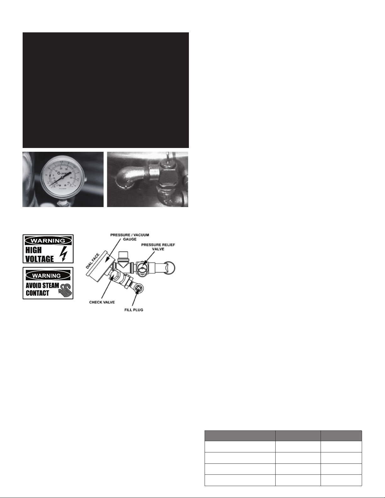
2. Pressure switch, set to open at about 46 PSI (345 kPa, 3.17 bars) and to shut
down the burners until jacket pressure is decreased.
3. Pop safety valve, which will release steam if jacket pressure exceeds 50 PSI
(345 kPa, 3.45 bars).
4. Tilt switch, which shuts off all burners when the kettle is tilted.
5. Gas pressure regulator built into the gas control valve.
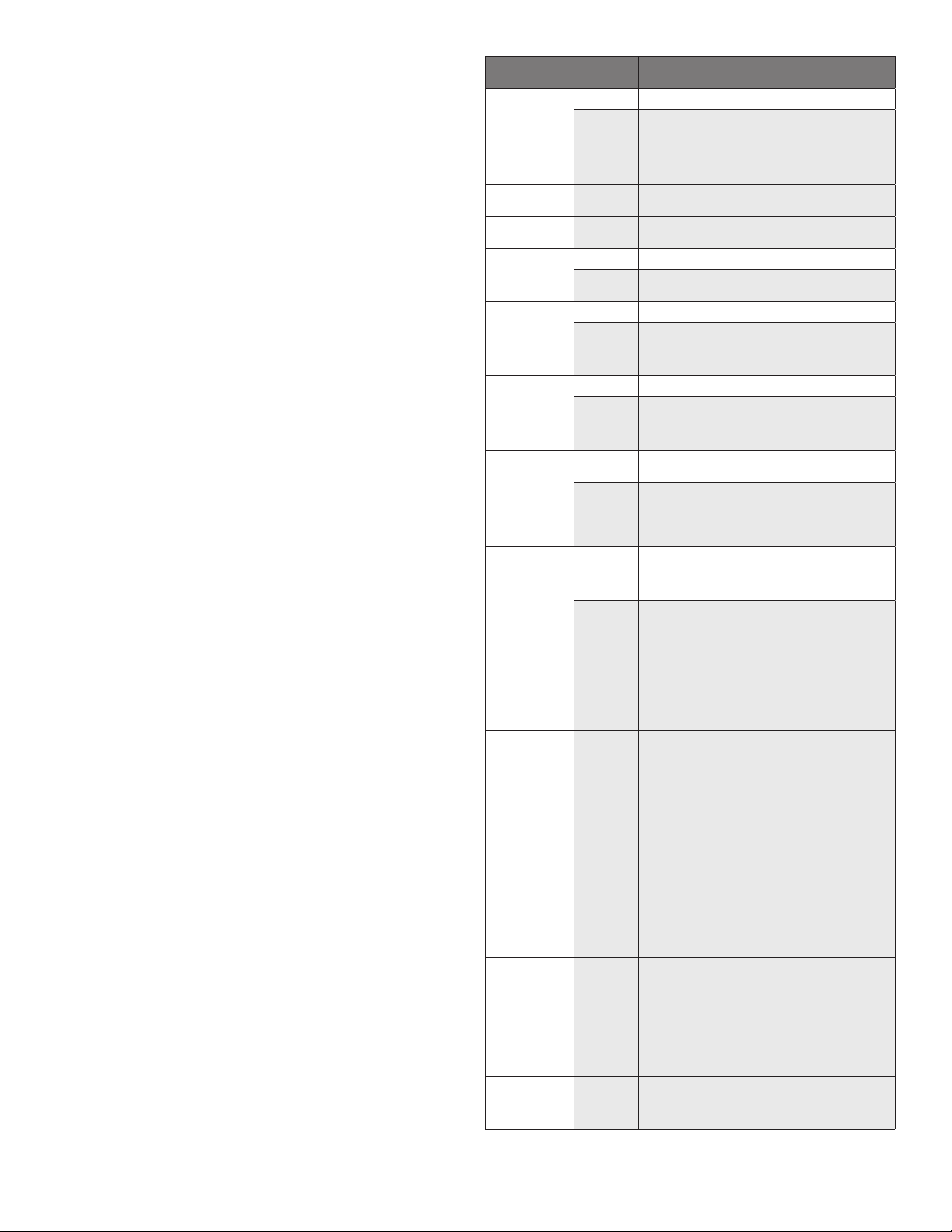
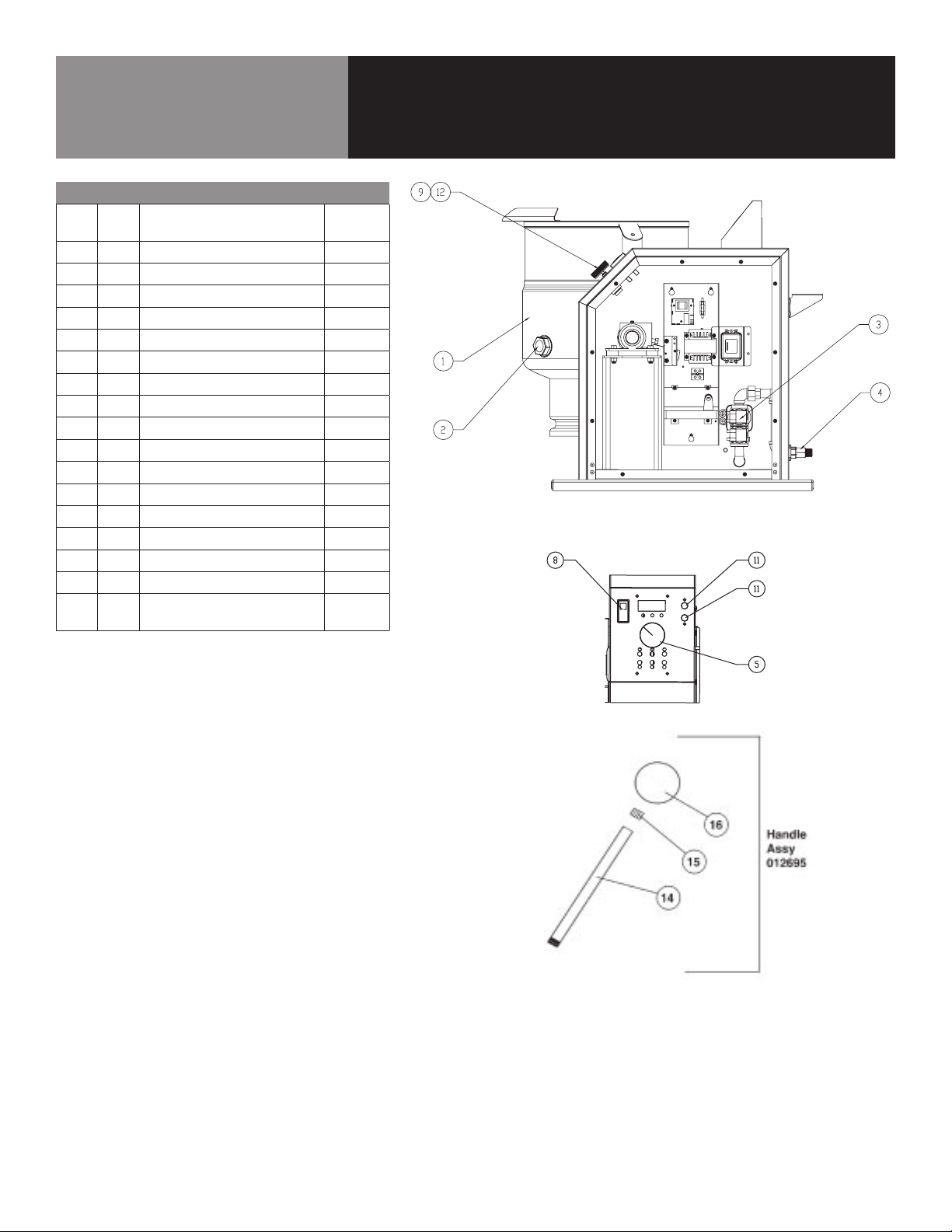
REPLACEMENT PARTS
To order parts, contact your Authorized Service Agent. Supply the model
designation, serial number, part description, part number, quantity, and when
applicable, voltage and phase.
CONTACT US
If you have questions pertaining to the content in this manual, contact Unified
Brands at 888-994-7636.
TROUBLESHOOTING
This unit is designed to operate smoothly and efficiently if properly maintained.
However, the following is a list of checks to make in the event of a problem.
Wiring diagrams are found at the end of this manual. When in doubt, turn unit
off and call for service at 888-994-7636. If an item on the check list is marked
with (X), it means that the work should be done by an Authorized Service Agent.
SYMPTOM WHO WHAT TO CHECK
X indicates items which must be performed by authorized technician.
Display not lit
(Advanced & C2T only)
User a.
That power supply is on.
Auth Service
Rep Only
b.
Fuses, accessible by removing caps on the side of the control box.
c.
For loose or broken wires. X
d.
Temperature controller functioning, by listening for a click
when the switch opens or closes and verifying LEDs on back
of board. X
e.
Contactor functioning. X
PROB in display
(Advanced & C2T only)
Auth Service
Rep Only
a.
For loose or broken wires or damaged/failed RTD probe. X
b.
PCB board malfunction/failure
HI in display
(Advanced & C2T only)
Auth Service
Rep Only
a.
For loose or broken wires or damaged/failed RTD probe. X
b.
PCB board malfunction/failure
Kettle is hard to tilt User a.
Gears for foreign materials, and lubrication.
Auth Service
Rep Only
b.
Gears for alignment. X
c.
Worm gears or broken gears. X
Kettle continues
heating after it
reaches the
desired temperature
User a.
Temperature Controller dial setting.
Auth Service
Rep Only
b.
Temperature Controller calibration and offset.X
c.
Temperature Controller operation. The Temperature Controller
should click when the dial is rotated to settings above and
below the temperature of the kettle.X
Kettle stops heating
before it reaches the
desired temperature
User a.
Temperature Controller dial setting.
Auth Service
Rep Only
b.
Temperature Controller calibration and offset.X
c.
Temperature Controller operation. The Temperature Controller
should click when the dial is rotated to settings above and
below the temperature of the kettle.X
Safety Valve pops
open
User
a. For air in the jacket. See “Jacket Vacuum” in the Maintenance
b. Temperature Controller dial setting.
Auth Service
Rep Only
c.
For defective Temperature Controller. The relay should click
when the dial is rotated to settings above and below the
temperature of the kettle. If defective, replace.X
d.
For defective safety valve. If the valve pops at pressures below
49 PSI, replace.X
Burners will not light User
a. That the main gas supply valve is open. (handle is in line with
gas pipe).
b. Gas supply to the building.
c. That the kettle body is not tilted.
Auth Service
Rep Only
d.
Temperature Controller operation. The relay should click
when the dial is rotated to settings above and below the
temperature of the kettle.X
e.
That tilt limit switch is closed when body is not tilted.X
System does not
produce a
spark
Auth Service
Rep Only
a.
AC voltage between terminals on secondary side of
transformer. If it is not 24 Volt, replace the transformer. X
b.
That the high tension cable is firmly attached and in good
condition. If cracked or brittle, replace.X
c.
Pilot electric ceramic for crack or break.X
d.
Pilot spark gap. Regap.X
Spark is present
but the pilot will
not light
Auth Service
Rep Only
a.
That the pilot valve is securely connected to terminals. X
b.
For 24 VAC at terminals PV and PV/MV. If 24V is not present,
replace the ignition control module. X
b.
That gas pressure is at least 3.5” W.C. (8.7818 ub).
c.
For gas at the pilot. If it is not flowing:
(1) Check the pilot gas line for kinks and obstructions. X
(2) Clean orifice, if necessary. X
(3) Check magnetic operator for pilot valve on gas valve.
Repair or replace as necessary. X
d.
That the pilot spark gap is located in the pilot gas stream. If
not, adjust or replace the pilot burner. X
e.
For drafts. Shield the pilot burner, if necessary. X
Pilot lights, but
main burner will
not come on and
spark does not
stay on
Auth Service
Rep Only
a.
For 24 V between terminals MV and PV/MV while pilot is burning.
If 24V is not present, replace the ignition control module. X
b.
That gas pressure is at least 3.5” W.C.(8.7818 ub). X
c.
Electrical connections of the main valve to terminals, to
assure that they are securely attached. Check magnetic
operator for main valve on gas valve. Repair or replace
as necessary. X
Pilot lights, but
main burner will
not come on, the
spark stays on
Auth Service
Rep Only
a.
Check for bad burner ground. If necessary, repair with
high temperature wire. X
b.
Pilot burner ceramic insulator for cracks. X
c.
That cable is not grounded out. If it is, correct the
ground-out condition or replace cable. X
d.
For proper gas pressure. X
e.
Clean pilot assembly, or replace if necessary. X
f.
Tighten all mechanical and electrical connections. X
g.
If the pilot flame is weak, increase pilot orifice size. X
h.
Replace ignition control module. X
Main burner
comes on but will
not stay on
Auth Service
Rep Only
a.
Check burner ground for bad wire or connection. Replace
if necessary with high temperature wire. X
b.
Check for low gas supply pressure. If necessary, replace
ignition control module. X

9 OM-TDH(C)-20/24/40/48 (C,A) (CE) INTERNATIONAL
Parts List
For Classic Control Models
Key Qty Description
Part No.
1 1 KETTLE BODY ASSY
CONSULT
FACTORY
2 1 GLASS, SITE ROUND
108554
3 1 GAS VALVE, CE MARK, G20
160776
3A 1 GAS VALVE, CE MARK, G31
160796
4 1 1/2” NPT TO 1/2” BSPT ADAPTER
116392
5 1 2" ALUMINUM KNOB
175095
6 1 VALVE, 1/4" SWING, CHECK
096915
7 1 GAUGE
084208
8 1 POWER SWITCH
177910
9 1 CONTROL, CLASSIC
174843
10 1 VALVE PRESSURE RELIEF
097005
11 2 LIGHT, AMBER
116384
12 1 ROTARY SHAFT SEAL
101145
13 1 SWITCH, PRESSURE (NOT SHOWN)
096963
14 1 SHAFT, HANDLE
018963
15 1 RING, 1/2"
012692
16 1 BALL, RED
012691
17 1 ELECTRODE, WATER LEVEL (NOT
SHOWN)
074623

10 OM-TDH(C)-20/24/40/48 (C,A) (CE) INTERNATIONAL
Key Qty Description
Part No.
1 1 KETTLE BODY ASSY
CONSULT
FACTORY
2 1 GLASS, SITE ROUND
108554
3 1 GAS VALVE, CE MARK, G20
160776
3A 1 GAS VALVE, CE MARK, G31
160796
4 1 1/2” NPT TO 1/2” BSPT ADAPTER
116392
5 1 2" ALUMINUM KNOB
174829
6 1 VALVE, 1/4" SWING, CHECK
096915
7 1 GAUGE
084208
8 1 POWER SWITCH
177910
9A 1 CONTROL, ADVANCED
174837
10 1 VALVE PRESSURE RELIEF
097005
11 2 LIGHT, AMBER
116384
12 1 ROTARY SHAFT SEAL
101145
13 1 SWITCH, PRESSURE (NOT SHOWN)
096963
14 1 SHAFT, HANDLE
018963
15 1 RING, 1/2"
012692
16 1 BALL, RED
012691
17 1 ELECTRODE, WATER LEVEL (NOT
SHOWN)
074623
x- Item not depicted/called out in drawing or photograph
Parts List
For Advanced Control Models

11 OM-TDH(C)-20/24/40/48 (C,A) (CE) INTERNATIONAL
Parts List
Key Description Part No.
1 NIPPLE, 3/8” NPT X 2”
005679
2 UNION, 3/8” NPT
005686
3 MANIFOLD,
5- AND 6-GALLON
137757
3 MANIFOLD,
10- AND 12-GALLON
137056
4 PILOT
097024
5 TUBE, PILOT
135487
6 PILOT ORIFICE SPUD NATURAL GAS
098648
6 PILOT ORIFICE SPUD PROPANE GAS
098647
7 FITTING, COMPRESSION 90 (NOT
SHOWN)
004584
8 ORIFICE SEE TABLE BELOW
-
Model
# of Orifices
Natural Gas
Propane Gas
Altitude
THD-20
TDHC-20 8
137758
137756 0 - 2000 ft.
TDH-24
TDHC-24 8
137758
137756 0 - 2000 ft.
TDH-40
TDHC-40 12
135543
137756 0 - 2000 ft.
TDH-48
TDHC-48 12
135543
137756 0 - 2000 ft.

12 OM-TDH(C)-20/24/40/48 (C,A) (CE) INTERNATIONAL
Parts List
Key Description
Part No.
1
WELDMENT, BASE
137060
2
WELDMENT, PEDESTAL
124735
3
WELDMENT, BASE SUPPORT
124729
4
WASHER LOCK 1/2" S.S.
005657
5
SCREW, HEX HD 1/2-13 X 1 1/4"
005623
6
NUT HEXAGON 1/2" - 13
005603
7
SCREW TRUSS HD 1/4-20 X 1/2 S.S.
012700
8
ASM, CABINET WELD
174762
9
SHROUD BURNER WELD ASM
135526
10
SHIELD, PILOT
135524
11
BURNER BRACKET WELD ASM.
135527
12
BRACKET, BURNER SUPPORT
137353
13
SCREW, TRUSS HD #8-32 X 3/8"
005764
14
SCREW, HED HD 1/4"-20 X 1/2"
005608
15
WASHER LOCK 1/4"
005655
16
SCREW HEX HD CAP 1/4"-20 X 1-1/2"
005469
17
NUT HEXAGON KEPS 1/4" - 20
012940
18
PLATE SHROUD WELD ASM
137680
19
SEAL TRUNNION
137005
20
PLATE, SHROUD WELD ASM (5/6-QT)
137700
20
PLATE, SHROUD WELD ASM (10/12-QT)
137380
21
GASKET, 3/8" THK X 1/2" WIDE, 6"
CENTER
137588
22
E-RING, 1.875" DIA
138357
23
FAUCET BRACKET
137738
24
GROMMET 7/8" ID X 1-5/8" OD
007400
25
COVER, CABINET
175309
26
SCREW, 10-32 X 1/2" COMBI HEAD
137766
27
CONNECTOR STRAIGHT 3/8" SEALTITE
001669
28
HARNESS ASM
137006
29
HARNESS ASM HIGH VOLTAGE
137546
30
STRAP CABLE TY-RAP
011093
31
SEALANT RTV #732, GREY
001711
Hand Tilt Units Only

13 OM-TDH(C)-20/24/40/48 (C,A) (CE) INTERNATIONAL
Parts List
Key Description
Part No.
1
WELDMENT, BASE
137060
2
WELDMENT, PEDESTAL
174792
3
WELDMENT, BASE SUPPORT
124729
4
WASHER LOCK 1/2" S.S.
005657
5
SCREW, HEX HD 1/2-13 X 1 1/4"
005623
6
NUT HEXAGON 1/2" - 13
005603
7
SCREW TRUSS HD 1/4-20 X 1/2 S.S.
012700
8
ASM, CABINET WELD
174799
9
SHROUD BURNER WELD ASM
135526
10
SHIELD, PILOT
135524
11
BURNER BRACKET WELD ASM.
135527
12
BRACKET, BURNER SUPPORT
137353
13
SCREW, TRUSS HD #8-32 X 3/8"
005764
14
SCREW, HED HD 1/4"-20 X 1/2"
005608
15
WASHER LOCK 1/4"
005655
16
SCREW HEX HD CAP 1/4"-20 X 1-1/2"
005649
17
NUT HEXAGON KEPS 1/4" - 20
012940
18
PLATE SHROUD WELD ASM
137680
19
SEAL TRUNNION
137005
20
PLATE, SHROUD WELD ASM (5/6-QT)
137700
20
PLATE, SHROUD WELD ASM (10/12-QT)
137380
21
GASKET, 3/8" THK X 1/2" WIDE, 6"
CENTER
137588
22
E-RING, 1.875" DIA
138357
23
FAUCET BRACKET
137738
24
GROMMET 7/8" ID X 1-5/8" OD
007400
25
COVER, CABINET
175309
26
SCREW, 10-32 X 1/2" COMBI HEAD
137766
27
CONNECTOR STRAIGHT 3/8" SEALTITE
001669
28
HARNESS ASM
137006
29
HARNESS ASM HIGH VOLTAGE
137546
30
STRAP CABLE TY-RAP
011093
31
SEALANT RTV #732, GREY
001711
32
O-RING #018
138359
33
E-RING, 1.00"
138356
34
COLLAR, SHAFT SEAL, .750"
138354
35
SEAL, SHAFT 1.00"
136088
Crank Tilt Units Only

14 OM-TDH(C)-20/24/40/48 (C,A) (CE) INTERNATIONAL
Parts List
Hand Tilt Units Only
Key Description
Part No.
1
SPACER, PILLOW BLOCK
137692
2
PILLOW BLOCK
002989
3
STOP, MANUAL TILT
137697
4
KEY, 1/4 SQ X .5” LG
137746
5
COLLAR SET 1-1/2” ID X 2-1/4” OD X
3/4” THK
003118
6
SCREW HEX HD CAP 3/8”-16 X 1-1/2”
005615
7
WASHER FLAT 3/8”
005830
8
NUT HEX 3/8”-16
005619
9
NUT HEX 5/16”-18
005602
10
SCREW SET SOCKET
086617
11
SCREW SET SOCKET
003400
12
SCREW HEX HD CAP 5/16”-18 X 1”
005613

15 OM-TDH(C)-20/24/40/48 (C,A) (CE) INTERNATIONAL
Parts List
Key Description
Part No.
1
ASSEMBLY, GEAR CARRIER
124741
2
SHAFT, WORM
122374
3
GEAR, WORM
128001
4
ASSEMBLY, GEAR SECTOR
128028
5
ASSEMBLY, BEARING BLOCK
128021
6
KEY, 1/4 SQ X 1” LG.
122371
7
RETAINING RING 1.500
124764
8
ASSEMBLY, HANDWHEEL
124719
9
PIN, ROLL 1/4” X 1.63 LG.
128036
10
WASHER, FLAT 3/8”
005830
11
WASHER, LOCK 3/8”
005618
12
SCREW, 3/8-16 X 1” HEX HD
005612
13
PIN, ROLL 1/4” X 1.25” LG.
012614
Crank Tilt Units Only

16 OM-TDH(C)-20/24/40/48 (C,A) (CE) INTERNATIONAL
Parts List
Key Qty Description Part No.
1 1 PRESSURE SWITCH
096963
2 1 RTD PROBE
175429
3 1 WATER LEVEL ELECTRODE
015589
4 1 BRACKET
137736
5 1 COVER (NOT SHOWN)
003141
6 1 GASKET, BOTTOM COVER
137969
7 1 SCREW, 1/4-20 X 1 1/2
012597
8 1 GASKET, BOTTOM COVER SCREW
137968
Key Description Part No.
1 GAUGE, COMPOUND PRESSURE W/
DUAL
084208
2 VALVE, PRESSURE RELIEF 50 PSI
097005
3 ASSY, WATER FILL SUB
137438
4 ELBOW, ½” NPT 90 DEG STREET BLK
096905

17 OM-TDH(C)-20/24/40/48 (C,A) (CE) INTERNATIONAL
Parts List
Key Qty Description
Part No.
1 1 ELEC. MOUNTING BRACKET
140420
2 1 CONTROL, WATER LEVEL, 24V
122192
3 1 MICRO SWITCH
002982
4 1 TERMINAL BLOCK, TWO POLE
003887
5 1 IGNITION MODULE
154059
6 1 FUSE, HOLDER, TYPE 3 AG
077854
7 1 FUSE, THREE AMP TYPE 3 AG
077853
8 1 SCREW, 6-32 X 3/8 LG (FOR #6)
009697
9 3 P.C. BOARD MOUNTING POST
099901
10 5 SCREW, 8 X 3/8 LG, HEX SLOT (FOR
#5 AND #17)
069789
11 1 SCREW, #8-32 X 1-1/4 RND HEAD
(FOR #4)
005056
12 2 SCREW, ROUND HEAD 4-40 X 3/4
LG. (FOR #3)
003122
13 1 BARRIER INSULATION (FOR #3)
003490
14 2 WASHER SHAKEPROOF LOCK, #6
(FOR #3)
005715
15 2 NUT, HEX 4-40 (FOR #3)
003121
16 1 TRANSFORMER, CE,
208/230/460 TO 24V
148899
17 1 LUG, GROUND
129714
18 1 BRACKET, EMI FILTER
177861
19 1 EMI FILTER
177768
Hand Tilt Units Only

18 OM-TDH(C)-20/24/40/48 (C,A) (CE) INTERNATIONAL
Parts List
Key Qty Description
Part No.
1 1 ELEC. MOUNTING BRACKET
175323
2 1 CONTROL, WATER LEVEL, 24V
122192
3 1 TERMINAL BLOCK, TWO POLE
003887
4 1 IGNITION MODULE
154059
5 1 FUSE, HOLDER, TYPE 3 AG
077854
6 1 FUSE, THREE AMP TYPE 3 AG
077853
7 1 SCREW, 6-32 X 3/8 LG (FOR #6)
009697
8 3 P.C. BOARD MOUNTING POST
099901
9 5 SCREW, 8 X 3/8 LG, HEX SLOT (FOR
#5 AND #17)
069789
10 1 SCREW, #8-32 X 1-1/4 RND HEAD
(FOR #4)
005056
12 1 TRANSFORMER, CE,
208/230/460 TO 24V
148899
13 1 LUG, GROUND
129714
14 1 BRACKET, EMI FILTER
177861
15 1 EMI FILTER
177768
x 1 SCREW, ROUND HEAD 4-40 X 3/4
LG. (FOR #3)
003122
x 1 BARRIER INSULATION (FOR #3)
003490
x 1 WASHER SHAKEPROOF LOCK, #6
(FOR #3)
005715
x 1 NUT, HEX 4-40 (FOR #3)
003121
x- Item not depicted/called out in drawing or photograph
Crank Tilt Units Only

19 OM-TDH(C)-20/24/40/48 (C,A) (CE) INTERNATIONAL
Wiring Diagram

20 OM-TDH(C)-20/24/40/48 (C,A) (CE) INTERNATIONAL
Service Log
Model No: Purchased From:
Serial No: Location:
Date Purchased: Date Installed:
Purchase Order No: For Service Call:
Date Maintenance Performed Performed By
This manual suits for next models
15
Table of contents
Other Groen Kettle manuals

Groen
Groen TDB/7 Operating manual

Groen
Groen EE Domestic User manual

Groen
Groen EE-20 User manual

Groen
Groen DH/1-40 User manual

Groen
Groen HH/4 User manual

Groen
Groen DEE/4-40C User manual

Groen
Groen DEES-40 User manual

Groen
Groen TDB Series User manual

Groen
Groen TDC/3-3 User manual

Groen
Groen AHS-40 User manual

Groen
Groen EE Domestic User manual

Groen
Groen DEE/4 Series Manual

Groen
Groen AH/1 User manual

Groen
Groen TDH Series User manual

Groen
Groen TDB/8-20-CFC User manual

Groen
Groen DHS-40 User manual

Groen
Groen TDBC-20 Operating manual

Groen
Groen EE-20 User manual

Groen
Groen D User manual

Groen
Groen DEE series Operating manual