10 OM-TDB/TDBC
Classic Control
Advanced Control
Operation
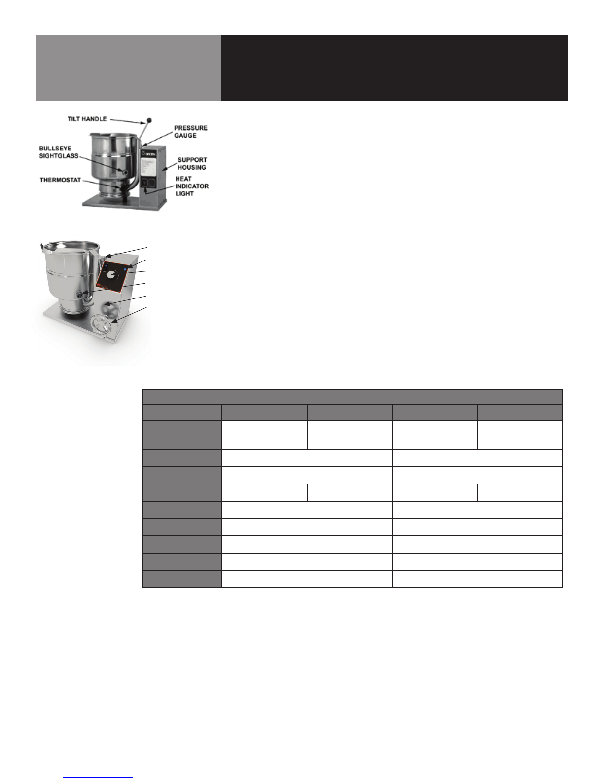
A. Controls
1. Classic Control (-XXC) Models
a. Lighted Power ON switch located on the control console.
Controls main power to the unit.
b. The temperature knob, located on the control console, is used
to set the kettle heat values between 1 and 10.
c. Heating indicator light located on the control console, lights
when the controller energizes the heating elements and will
cycle on and off once the unit reaches set temperature. If
the unit is tilted, the heating elements will be disabled and
the light will turn off until the unit is returned to the cooking
position.
d. A LOW WATER indicator light, located on the control console,
illuminates when the jacket water falls below acceptable
levels. When lit, the heating elements are disabled and
will not function until the jacket water is refilled using the
procedure on p. 18 of this manual.
e. Crank tilt - a handle controls the worm and gear mechanism
that smoothly tilts the kettle body and holds it in the desired
position.
2. Advanced Control (-XXA) models
a. i. Lighted Power ON switch located on the control console.
Controls main power to the unit.
b. The temperature knob, located on the control console, is used
to set the kettle heat values between 1 and 10. The current
setting will be reflected on the display.
c. Heating indicator light located on the control console, lights
when the controller energizes the heating elements and will
cycle on and off once the unit reaches set temperature. If
the unit is tilted, the heating elements will be disabled and
the light will turn off until the unit is returned to the cooking
position.
d. A LOW WATER indicator light, located on the control console,
illuminates when the jacket water falls below acceptable
levels. When lit, the heating elements are disabled and
will not function until the jacket water is refilled using the
procedure on p. 18 of this manual.
e. SET TnnP Mode - Allows power to the controller without
the kettle heating; the kettle will heat once the LOW TEMP,
MANUAL or HIGH TEMP button is selected.
f. LOW TEMP Button – Used to set operating temperature of the
kettle at a preset low intensity (default = 2). Can be pressed
at any time during operation of the unit to change the set
temperature to the preset value except when there is an
active TIMER enabled.
g. MANUAL Mode button – Enables the user modify the desired
cooking temperature of the kettle (between 1 and 10)
using the temperature knob and display (default = 4). The
operator will press the MANUAL button and set the desired
temperature using the temperature knob and display. Once
the desired temperature is reached, the user may either
press the MANUAL button again or wait 5 seconds and the