GR-UM-319-A-00
You can view information by pressing the button.
Switch the display interface or
increase the value by one
Access the settings or confirm your
setting
Return to the previous display
interface
Restore to factory settings
Inverter status indicator
The LCD screen displays the basic information about the inverter,
including PV/AC voltage, PV power, AC current, the total power and
capacity.
Shenzhen Growatt New Energy Co., Ltd
4-13/F, Building A, Sino-German (Europe) Industrial Park,
Hangcheng Ave, Bao’an District, Shenzhen, China
+86 755 2747 1942
www.ginverter.com
T
E service@ginverter.com
W
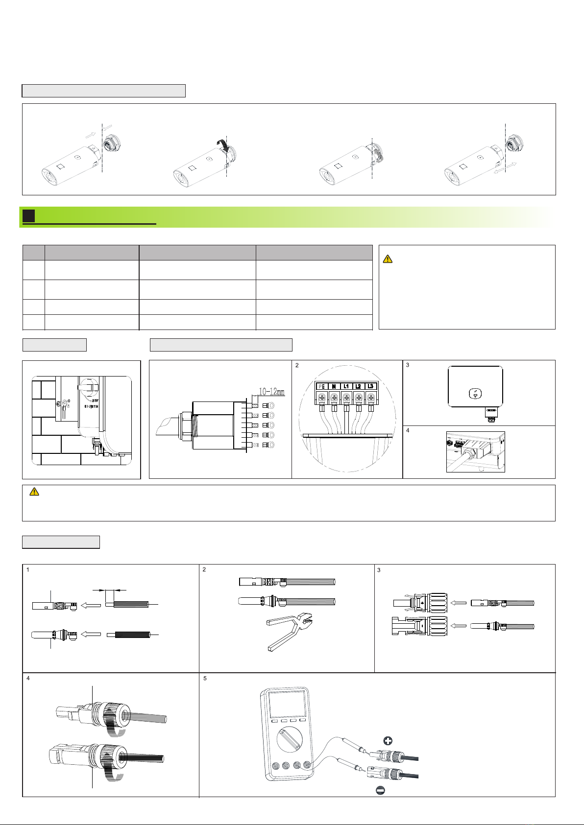
1.Before installing the PV terminal,please
double-check that the PV input voltage and
current do not exceed the MPPT limits.
2.Ensure the correct polarity when
connecting the positive and negative PV
terminals to the inverter.
3.Ensure that you hear a "click" sound
which indicates a robust connection. Gently
pull the cables back to ensure that they are
securely connected.
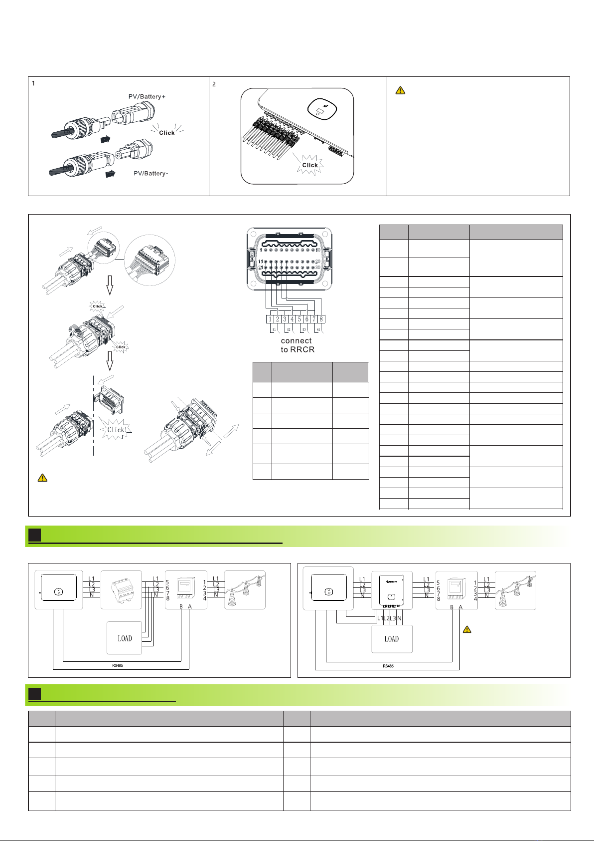
3.3.3 Connecting the communication cable
The inverter is installed correctly, firmly and reliably.
The RS485 communication cable is installed correctly and firmly.
The PE cables are properly and securely connected.
The cable ties are well-trimmed, without any sharp edges
All exposed terminals are well protected and there are no vacant
ports.
All electrical connections are correct and secured.
Remove the installation residues.
The cable wiring is reasonable and meets all
requirements. No frayed or cracked wire is used.
Download
Manual
Growatt New Energy
3.3.2 Connecting the PV/BAT terminals
The following diagrams illustrate the way to connect the EASTRON meter (TOM-E) and the Backup Box to the inverter:
Note:
Exporlimit
OFF ON
Password
123
Settings
General
Advanced Meter
Export Limit Rate
XXX.X%
OK
For regions where the local grid company
poses restrictions on the power output of your
solar system, we introduce the concept of
Export Limit Rate, which refers to the ratio of
the output power to the rated power of the
inverter. For example, if the local grid
company permits only 4kW from your 5kW
system, then the Export Limit Rate for the 5kW
inverter would be 80%.
Before turning the inverter on, please make sure the PV input voltage and current are within the MPPT limits.
Follow the steps below to turn the inverter on:
1.Switch on the built-in DC switch at the bottom of the inverter.
2.Switch on the PV Array and DC isolator next to your inverter. If the switch is not available, skip this step.
3.Switch on the Solar AC isolator if the inverter is more than 3 meters away from your switchboard.
4.Switch on the solar supply main switch in the switch board.
To shut down your system, follow the reverse order of the steps mentioned above.
If a backup box is connected, please
enable it when configuring the
inverter. For details, please refer to
Section 9.3.3 in the MID 11-30KTL3-
XH User Manual.
Note:
485B4
485A4
Pin1 7 Pin 18
Pin5 P in6
485A2
485B2
COM Po rt
Pin5 P in6
COM Po rt
485A2
485B2
4.
Connecting the Meter and the Backup Box
5.
Post-installation check
6.
Powering on/off the inverter
7.
Status of PV grid inverter
8.
Export limitation setting
9.
Service and contact
Note:
The Inverer Side
The Inverer Side
1. When connecting the communication cable, do not connect to Port 15 and Port 16.
For other port definitions,please refer to the table above.
2. When connecting to the battery, Port 9 and Port 10 must be connected.
Note:
Dry contact:the power
of any external wiring
connected to it should
not be greater than 2W
Battery communication
port
Backup box
identification signal
Battery communication
port 2


 User manual")