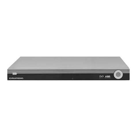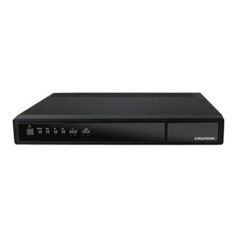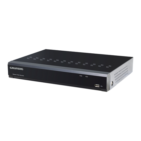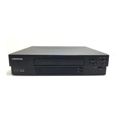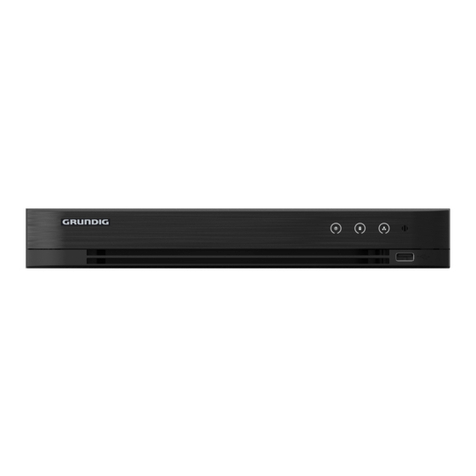
Allgemeiner Teil / General Section GV 32…, GV 52…, GV 62…
1 - 2 GRUNDIG Service
Es gelten die Vorschriften und Sicherheitshinweise
gemäß dem Service Manual "Sicherheit", Material-
nummer 720108000000, sowie zusätzlich die eventu-
ell abweichenden, landesspezifischen Vorschriften!
The regulations and safety instructions shall be valid
as provided by the "Safety" Service Manual, part
number 720108000000, as well as the respective
national deviations.
GB
Table of Contents
Page
General Section .................................. 1-3…1-32
Video Recorder Overview ............................................................ 1-3
Test Equipment / Jigs .................................................................. 1-4
Specifications ............................................................................... 1-4
Service Instructions ...................................................................... 1-5
Operating Hints .......................................................................... 1-20
Adjustment Procedures................................ 2-2
Layout of the PCBs
and Circuit Diagrams ......................... 3-1…3-28
Wiring Diagram ............................................................................ 3-1
Chassis Board .............................................................................. 3-2
•System/Drive Control (SC) ........................................................ 3-7
•Tuner/Modulator (TM) ............................................................. 3-10
•IN/OUT, 1 EURO-AV (IO) ....................................................... 3-11
•IN/OUT, 2 EURO-AV –Mono (IO) .......................................... 3-12
•IN/OUT, 2 EURO-AV –HiFi (IO) ............................................. 3-13
•Audio/Video (VS) .................................................................... 3-14
•SECAM (SE) ........................................................................... 3-17
•OSD/VPS/PDC (OS) ............................................................... 3-18
•Stereo/NICAM Decoder (A2/NIC) ........................................... 3-19
•FM Sound (HiFi) ...................................................................... 3-20
•Power Supply .......................................................................... 3-22
Keyboard Control Unit left (KL) .................................................. 3-23
Keyboard Control Unit right (KR) ............................................... 3-23
Block Circuit Diagram ................................................................ 3-25
Oscillograms .............................................................................. 3-26
Drive Mechanism................................ 4-6…4-10
Test Equipment / Jigs .................................................................. 4-6
Overview of the Drive Mechanism ............................................... 4-6
Disassembly Instructions ............................................................. 4-7
Adjustments ............................................................................... 4-10
Exploded Views and
Spare Parts Lists ................................ 5-1…5-18
D
Inhaltsverzeichnis
Seite
Allgemeiner Teil ................................. 1-3…1-19
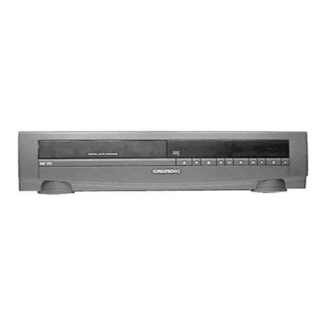
Geräteübersicht ........................................................................... 1-3
Messgeräte / Messmittel .............................................................. 1-4
Technische Daten ........................................................................ 1-4
Servicehinweise ........................................................................... 1-5
Bedienhinweise ............................................................................ 1-7
Abgleichvorschriften .................................... 2-1
Platinenabbildungen
und Schaltpläne ................................. 3-1…3-28
Verdrahtungsplan ......................................................................... 3-1
Chassisplatte ............................................................................... 3-2
•System-/Laufwerksteuerung (SC) ............................................. 3-7
•Tuner/Modulator (TM) ............................................................. 3-10
•IN/OUT, 1 EURO-AV (IO) ....................................................... 3-11
•IN/OUT, 2 EURO-AV –Mono (IO) .......................................... 3-12
•IN/OUT, 2 EURO-AV –HiFi (IO) ............................................. 3-13
•Audio/Video (VS) .................................................................... 3-14
•SECAM (SE) ........................................................................... 3-17
•OSD/VPS/PDC (OS) ............................................................... 3-18
•Stereo/NICAM Decoder (A2/NIC) ........................................... 3-19
•FM-Ton (HiFi) .......................................................................... 3-20
•Netzteil (PS) ............................................................................ 3-22
Bedieneinheit links (KL) ............................................................. 3-23
Bedieneinheit rechts (KR) .......................................................... 3-23
Blockschaltplan .......................................................................... 3-25
Oszillogramme ........................................................................... 3-26
Laufwerk ............................................... 4-1…4-5
Messgeräte / Messmittel .............................................................. 4-1
Laufwerkübersicht ........................................................................ 4-1
Ausbauhinweise ........................................................................... 4-2
Einstellungen ............................................................................... 4-5
Explosionszeichnungen
und Ersatzteillisten ............................ 5-1…5-18
