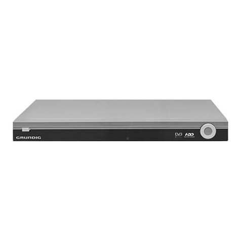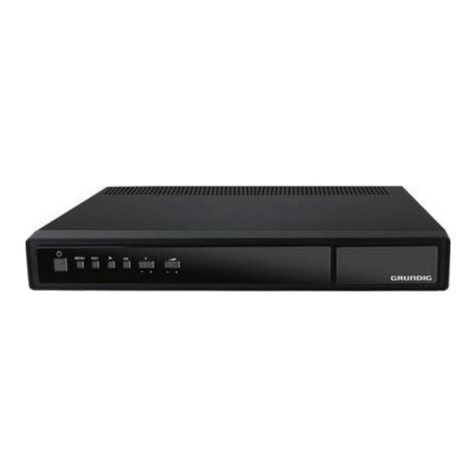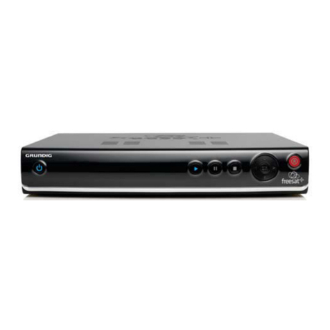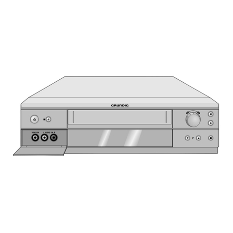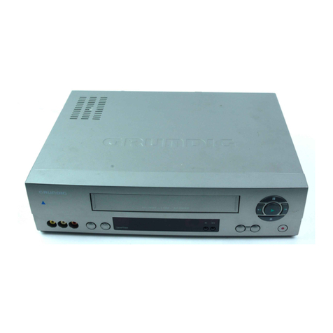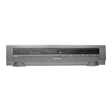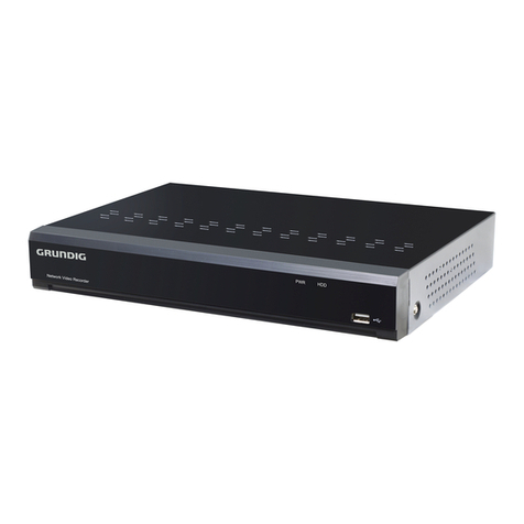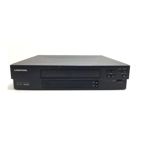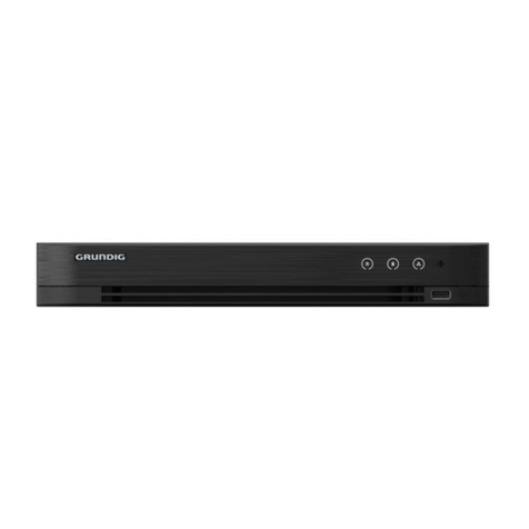
Allgemeiner Teil / General Section GV 64 …, GV 65 …, GV 66 …, SE 6106 HiFi
1 - 2 GRUNDIG Service
Es gelten die Vorschriften und Sicherheitshinweise
gemäßdemServiceManual"Sicherheit",Sach-Num-
mer 72010-800.00, sowie zusätzlich die eventuell
abweichenden, landesspezifischen Vorschriften!
Theregulationsandsafetyinstructionsshallbevalid
as provided by the "Safety" Service Manual, part
number 72010-800.00, as well as the respective
national deviations.
GB
Table of Contents Page
General Section..................................1-1…1-16
Videorecorder Overview .............................................................. 1-3
Test Equipment / Jigs .................................................................. 1-5
Specifications............................................................................... 1-5
Operating Hints .......................................................................... 1-10
Service Instructions.................................................................... 1-13
Service Test Programme and
Special Functions ................................2-4…2-6
Adjustment Procedures.......................3-4…3-6
Power Supply (PS)....................................................................... 3-4
Keyboard Control Unit (DC) ......................................................... 3-4
Frontend (FE) /
Family Board – Tuner/Modulator Interface (TM)....................... 3-4
Family Board................................................................................ 3-5
• Sequence Control / Deck Control (CC / DE) ............................. 3-5
• Video/Chroma (VS) ................................................................... 3-5
• OSD (OS).................................................................................. 3-5
IO Board – Audio (AU) ................................................................. 3-6
• FM Sound ................................................................................. 3-6
• Standard Sound ........................................................................ 3-6
Teletext "DOS" (VT) ..................................................................... 3-6
Layout of the PCBs
& Circuit Diagrams.............................4-1…4-88
Note on the Components / Circuit Diagrams Symbols................. 4-1
Wiring Diagrams .......................................................................... 4-7
Block Circuit Diagrams............................................................... 4-15
Power Supply (PS)..................................................................... 4-23
Frontend / NICAM (FE) .............................................................. 4-26
IO Board..................................................................................... 4-31
• IN/OUT (IO)............................................................................. 4-33
• Audio (AU) .............................................................................. 4-36
Teletext "DOS" (VT) ................................................................... 4-39
Family Board.............................................................................. 4-41
• Sequence Control (CC)........................................................... 4-47
• Deck Control / Deck Electronic (DE) ....................................... 4-51
• Video/Chroma (VS) ................................................................. 4-55
• Head Amplifier (HC) ................................................................ 4-59
• Tuner/Modulator Interface (TM) .............................................. 4-61
• OSD (OS)................................................................................ 4-62
• VPS (VP)................................................................................. 4-62
Keyboard Control Unit (PDCGN1 / DC) ..................................... 4-63
Keyboard Control Unit II (PCUGN11/12 / CU) ........................... 4-65
Keyboard Control Unit (PDCGN2 / DC) ..................................... 4-71
Keyboard Control Unit II (PCUGN21 / CU) ................................ 4-73
Keyboard Control Unit (PDCGN3 / DC) ..................................... 4-79
Keyboard Control Unit II (PCUGN31 / CU) ................................ 4-81
Oscillograms .............................................................................. 4-85
Drive Mechanism................................5-1…5-12
Test Equipment / Jigs .................................................................. 5-1
Service Instructions...................................................................... 5-2
Replacement of Tape Deck Components .................................... 5-3
Adjustments ............................................................................... 5-10
Exploded Views and
Spare Parts Lists................................6-1…6-15
D
Inhaltsverzeichnis Seite
Allgemeiner Teil .................................1-1…1-16
Geräteübersicht ........................................................................... 1-3
Meßgeräte / Meßmittel................................................................. 1-5
Technische Daten ........................................................................ 1-5
Bedienelemente ........................................................................... 1-7
Servicehinweise ......................................................................... 1-13
Servicetestprogramm
und Sonderfunktionen......................... 2-1…2-3
Abgleichvorschriften ........................... 3-1…3-3
Netzteil (PS)................................................................................. 3-1
Bedieneinheit (DC)....................................................................... 3-1
Empfangseinheit (FE) /
Chassisplatte – Tuner/Modulator-Interface (TM) ...................... 3-1
Chassisplatte ............................................................................... 3-2
• Ablaufsteuerung / Laufwerksteuerung (CC / DE)...................... 3-2
• Video/Chroma (VS) ................................................................... 3-2
• OSD (OS).................................................................................. 3-2
IO-Platte – Audio (AU) ................................................................. 3-3
• FM-Ton ..................................................................................... 3-3
• Standardton .............................................................................. 3-3
Teletext "DOS" (VT) ..................................................................... 3-3
Platinenabbildungen
& Schaltpläne .....................................4-1…4-88
Hinweise zu den Bauteilen / Schaltplansymbole ......................... 4-1
Verdrahtungspläne....................................................................... 4-7
Blockschaltpläne ........................................................................ 4-15
Netzteil (PS)............................................................................... 4-23
Empfangseinheit / NICAM (FE).................................................. 4-26
IO-Platte..................................................................................... 4-31
• IN/OUT (IO)............................................................................. 4-33
• Audio (AU) .............................................................................. 4-36
Teletext "DOS" (VT) ................................................................... 4-39
Chassisplatte ............................................................................. 4-41
• Ablaufsteuerung (CC) ............................................................. 4-47
• Laufwerksteuerung / Deck-Elektronik (DE) ............................. 4-51
• Video/Chroma (VS) ................................................................. 4-55
• Kopfverstärker (HC) ................................................................ 4-59
• Tuner/Modulator Interface (TM) .............................................. 4-61
• OSD (OS)................................................................................ 4-62
• VPS (VP)................................................................................. 4-62
Bedieneinheit (PDCGN1 / DC)................................................... 4-63
Bedieneinheit II (PCUGN11/12 / CU)......................................... 4-65
Bedieneinheit (PDCGN2 / DC)................................................... 4-71
Bedieneinheit II (PCUGN21 / CU).............................................. 4-73
Bedieneinheit (PDCGN3 / DC)................................................... 4-79
Bedieneinheit II (PCUGN31 / CU).............................................. 4-81
Oszillogramme ........................................................................... 4-85
Laufwerk ............................................. 5-1…5-12
Meßgeräte / Meßmittel................................................................. 5-1
Servicehinweise ........................................................................... 5-2
Auswechseln von Laufwerksteilen ............................................... 5-3
Einstellungen ............................................................................. 5-10
Explosionszeichnungen
und Ersatzteillisten ............................ 6-1…6-15
