Sonoclock 51 SC 5301
ǵ
EQUIPMENT REQUIRED
Signal Source
1.MW/LW signal generator (AM SG)
2. FM signal generator (FM SG)
3. Sweep generator (10.7 M z for FM)
Output Indicator
1. SSVM
2. Oscilloscope
3. Frequency Counter
General preparation
1. C eck source voltage.
2. Set function switc to band being aligned
3. Turn volume control to minimum (unless noted ot erwise)
4. Connect low side of signal and output indicator to c assis ground unless ot erwise specified.
Keep ground connection close to ig side connection.
5. Keep signal inout as low as possible to avoid AGC and AFC action
(set output indicator to ig sensitivity.)
6. Standard modulation is 1000 Hz AT 30% amplitude for MW/LW (1000 Hz at 22.5 kHz deviation for FM)
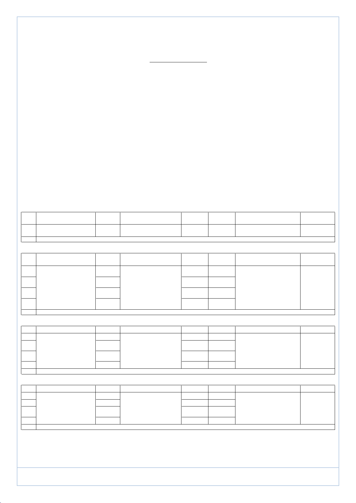
AM IF ALIGNMENT
Step Signal source (AM RF Gen) Connect
to Set signal to Aligment indicator connect to
Oscilloscope or SSVM Set radio dial to Adjust Adjust for Remarks
1 A standard radiation loop 460 KHz T4 Detector Output Terminal Quiet point T3 Maximum Volume control min
position
2 Repeat for maximum output
MW RF ALIGNMENT
Signal source (AM Signal Gen.)
connect to Set signal to Alignment indicator Connect to Set radio dial to Adjust Adjust for Remarks
1515 KHz
(modulated) 515 KHz
(lowest end) T1 (Osc,
coil)
21640 KHz
(modulated) 1640 KHz
(Hig est end) TC4
(Osc, trim)
3600 KHz
(modulated) 600 KHz L2 (ant coil)
41440 KHz
(modulated) 1440KHz TC3 (ant trim)
5 Repeat Steps 3 and 4 as necessary to minimize tracking error. Also repeat steps 1 and 2 if necessary.
LW RF ALIGNMENT
Signal source (AM Signal Gen.)
Set signal to Alignment indicator Connect to Set radio dial to Adjust Adjust for Remarks
1140 KHz
140 KHz
T2 (Osc,
2290 KHz
(modulated) 290 KHz
(Hig est end) TC6 (Osc,
trim)
3153 KHz
(modulated) 153 KHz L3(ant coil)
4261 KHz
261 KHz TC5 (ant trim)
5 Repeat Steps 3 and 4 as necessary to minimize tracking error. Also repeat steps 1 and 2 if necessary.
FM RF ALIGNMENT
Step Signal source (FM Signal Gen.)
Set signal to Alignment indicator (oscilloscope ,
Set radio dial to Adjust Adjust for Remarks
187.35 MHz
87.35MHz
L1 (Osc, coil)
2108.25 MHz
108.25MHz
TC2
390 MHz
modulated 90MHz L2
RF coil
stretc or
4106 MHz
106MHz TC1 (RF trim)
5 repeat steps 3 and 4 as necessary to minimum tracking error. Also repeat steps 1 and 2 if necessary.
* UK models must not be able to tune below 87.5 MHz.
Across speaker voice coil Maximum Volume control max-
position
TP 1, GND (Test point) t roug
matc ing network if necessary Across speaker voice coil Maximum Volume control Max-
position
A standard radiation loop antenna
ALIGNMENT PROCEDURE
MODEL NO. GRUNDIG SONOCLOCK SC 51
A standard radiation loop antenna Across speaker voice coil Maximum Volume control max-
position