GSi 40 Series Instructions for use

PNEG-4018B
18' Diameter Bin - Beta
40-Series 2.66" Corrugation Bin
6000 lb. Peak Load Roof
Construction Manual
PNEG-4018B
Version: 1.2
Date: 11-17-20

2 PNEG-4018B 40-Series 2.66" Corrugation 18' Diameter Bin - Beta
All information, illustrations, photos, and specifications in this manual are based on the latest
information available at the time of publication. The right is reserved to make changes at any
time without notice.

Table of Contents
PNEG-4018B 40-Series 2.66" Corrugation 18' Diameter Bin - Beta 3
Contents
Chapter 1 Safety ..................................................................................................................................................... 5
Safety Guidelines .................................................................................................................................. 5
Cautionary Symbols Definitions ............................................................................................................ 6
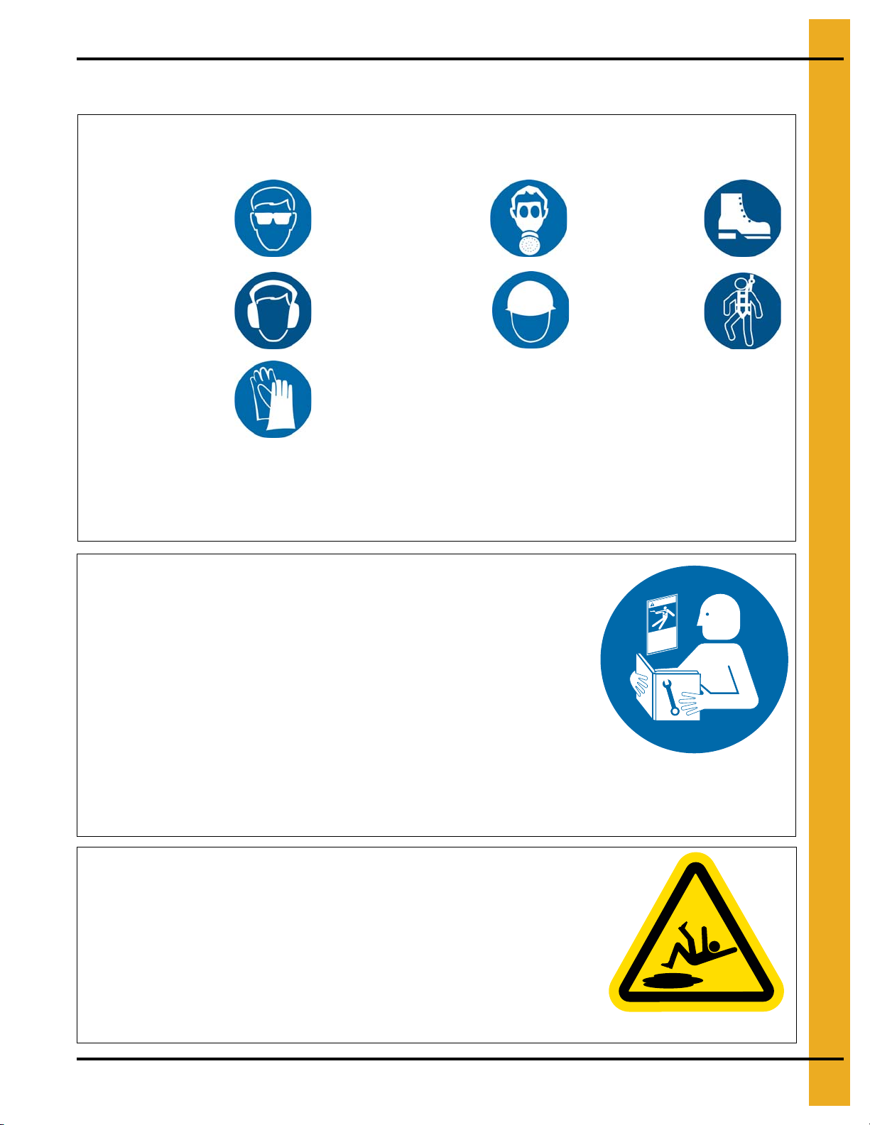
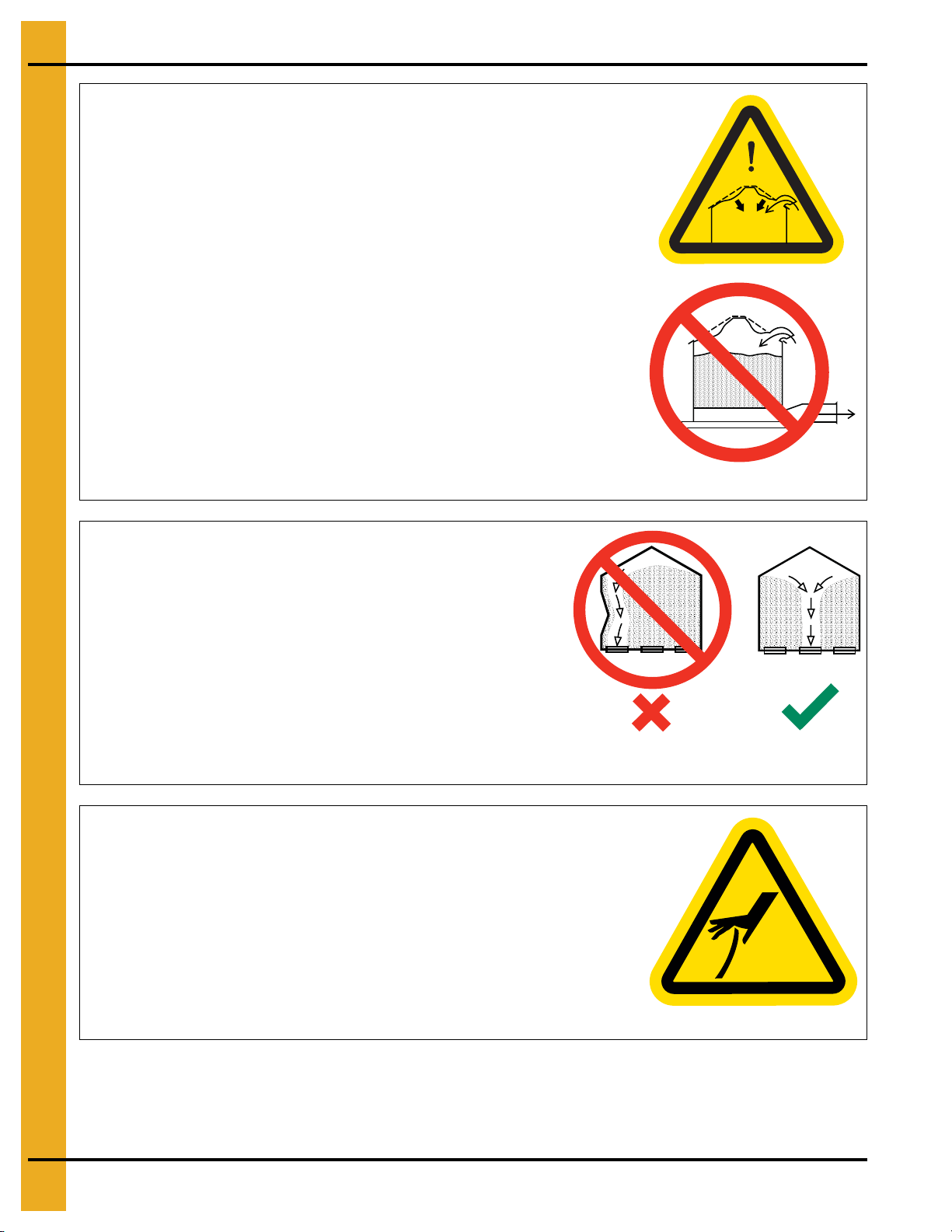
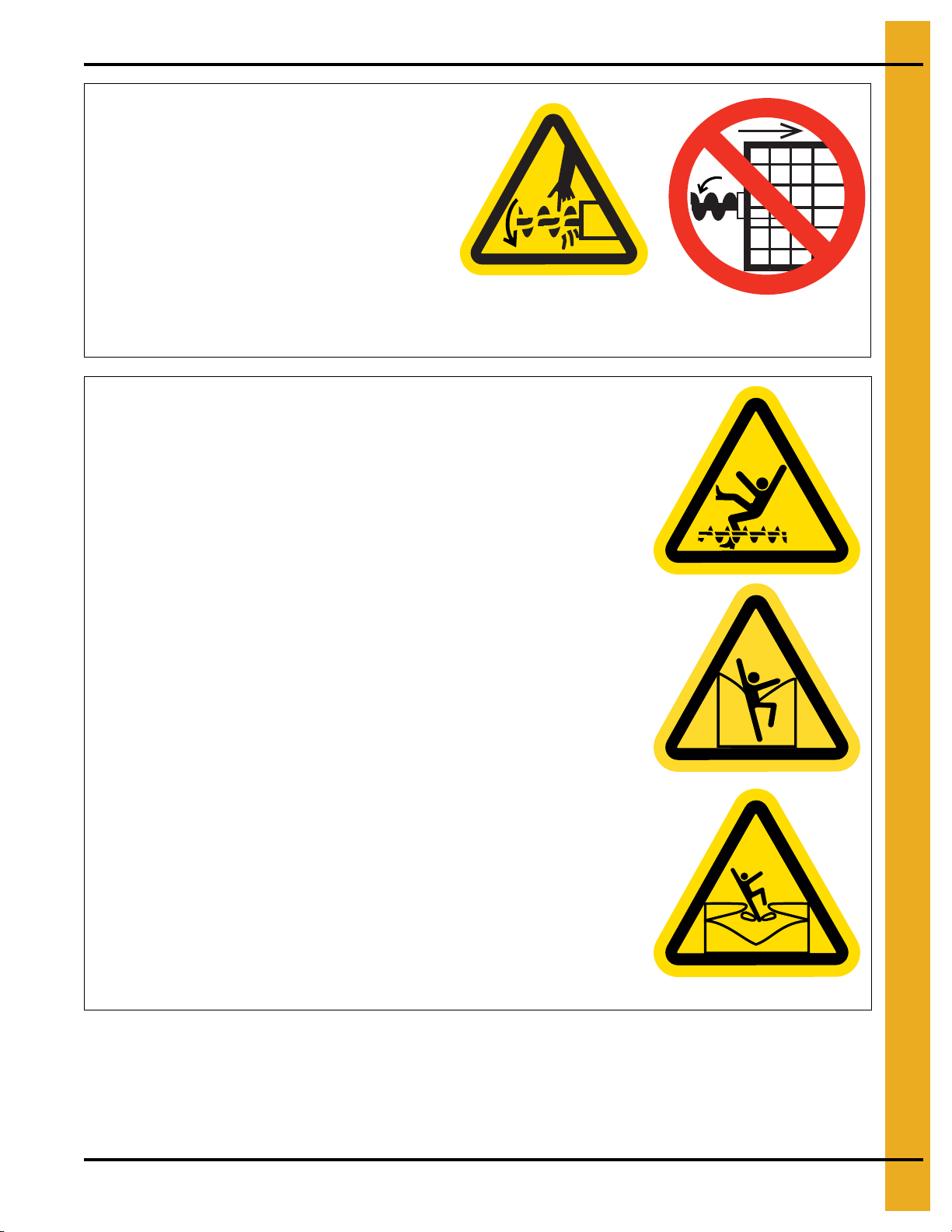
Safety Cautions ..................................................................................................................................... 7
Safety Sign-Off Sheet ......................................................................................................................... 11
Chapter 2 Decals .................................................................................................................................................. 12
Overfill Warning ................................................................................................................................... 14
Chapter 3 General Overview ............................................................................................................................... 15
General Information ............................................................................................................................ 15
Anchor Bolt Charts .............................................................................................................................. 15
Tools Required for Construction ......................................................................................................... 17
Guidelines for Proper Storage of Grain Bin Materials Prior to Construction ....................................... 17
Guidelines for Construction Procedures and Lifting Jack Usage ........................................................ 18
Instructions for Stirring Devices .......................................................................................................... 19
Guidelines for Placement of the Decal Sidewall Sheet ....................................................................... 20
Chapter 4 Bolt and Nut Usage ............................................................................................................................ 21
Hardware Requirements for Sidewalls and Stiffeners ......................................................................... 21
Bolt Identification ................................................................................................................................. 24
Color Chart for Bin Hardware Bucket Lids .......................................................................................... 28
Chapter 5 Assembling Sidewall Sheets ............................................................................................................. 29
Color Codes for Sidewall Gauge Identification .................................................................................... 29
Caulking Detail for Standard (Non-Laminated) Sheets ....................................................................... 30
Caulking Detail for Laminated Quad Pattern Sheets .......................................................................... 32
Chapter 6 Base Angle Installation ...................................................................................................................... 35
Installing the Base Angle ..................................................................................................................... 35
Anchor Bolt Detail ............................................................................................................................... 36
Installing the Base Angle Shims .......................................................................................................... 37
Anchor Bolt Washer Installation .......................................................................................................... 38
Chapter 7 Stiffeners ............................................................................................................................................. 39
Stiffener Part Number Description ...................................................................................................... 39
Color Codes for Stiffener Gauge Identification .................................................................................... 39
Outside Stiffened Laminated Stiffener to Sidewall
(10 Gauge Laminated and Thicker Only) ............................................................................................ 40
Standard Stiffeners ............................................................................................................................. 41
Top Stiffeners ...................................................................................................................................... 42
Stiffeners Splice .................................................................................................................................. 43
Base Stiffeners .................................................................................................................................... 44
Base Boots .......................................................................................................................................... 45
Close-Punch Connection for a 1 Ring Top Stiffener (15-16 Gauge) and
a 2 Ring Stiffener (15-16 Gauge) ........................................................................................................ 45
Close-Punch Connection for a 1 Ring Top Stiffener (10-14 Gauge) and
a 2 Ring Stiffener (8-14 Gauge) .......................................................................................................... 46
Close-Punch Connection for a 1 Ring Top Stiffener (10-14 Gauge) and
a 2 Ring Stiffener (15-16 Gauge) ........................................................................................................ 46
2 Ring Top Stiffener (15-16 Gauge) to a 2 Ring Stiffener (15-16 Gauge) Connection ....................... 47
2 Ring Top Stiffener (8-14 Gauge) to a 2 Ring Stiffener (15-16 Gauge) Connection ......................... 47
2 Ring Top Stiffener (8-14 Gauge) to a 2 Ring Stiffener (8-14 Gauge) Connection ........................... 48
Close-Punch Connection for a 2 Ring Top Stiffener (16 Gauge) to a 2 Ring Stiffener (16 Gauge) .... 48
Close-Punch Connection for a 2 Ring Top Stiffener (16 Gauge) to a 2 Ring Stiffener (8-14 Gauge) . 49
2 Ring Stiffener (15-16 Gauge) to a 2 Ring Stiffener (15-16 Gauge) Connection ............................... 49
Close-Punch Connection for a 2 Ring Stiffener (16 Gauge) to a 2 Ring Stiffener (16 Gauge) ........... 50

Table of Contents
4 PNEG-4018B 40-Series 2.66" Corrugation 18' Diameter Bin - Beta
2 Ring Stiffener (8-14 Gauge) to a 2 Ring Stiffener (8-14 Gauge) Connection ................................... 50
Close-Punch Connection for a 2 Ring Stiffener (8-14 Gauge) to a 2 Ring Stiffener (8-14 Gauge) ..... 51
Close-Punch Connection for a 2 Ring Stiffener (2-6 Gauge) to a 2 Ring Stiffener (2-6 Gauge) ......... 51
2 Ring Stiffener (8-14 Gauge) to a Close-Punch Base Stiffener (8 Gauge) Connection .................... 52
2 Ring Stiffener (8-14 Gauge) to a Close-Punch Base Stiffener (2-6 Gauge) Connection ................. 53
Close-Punch Connection for a 2 Ring Stiffener (8-14 Gauge) to a Base Stiffener (8 Gauge) ............ 54
Close-Punch Connection for a 2 Ring Stiffener (2-6 Gauge) to a Base Stiffener (2-6 Gauge) ........... 55
2 Ring Stiffener (8-14 Gauge) to a Base Stiffener (10-14 Gauge) Connection ................................... 56
2 Ring Stiffener (15-16 Gauge) to a Base Stiffener (10-14 Gauge) Connection ................................. 57
Close-Punch Connection for a 2 Ring Stiffener (16 Gauge) to a Base Stiffener (10-14 Gauge) ........ 57
Close-Punch 2 Ring Stiffener (2-6 Gauge) to a Laminated Stiffener (2 Gauge)
with an Insert (10-12 Gauge) .............................................................................................................. 58
Close-Punch 2 Ring Stiffener (2-6 Gauge) to a Laminated Stiffener (2 Gauge)
with an Insert (10-12 Gauge) .............................................................................................................. 58
Close-Punch Laminated Stiffeners (2 Gauge) with an Inserts (10-12 Gauge) .................................... 59
Close-Punch Laminated Stiffener (2 Gauge) with an Insert (10-12 Gauge)
to a Laminated Base Stiffener (2 Gauge) with a Base Insert (10-12 Gauge) ...................................... 59
Base Stiffener (10-14 Gauge) to a Base Boot Connection ................................................................. 60
Close-Punch Connection for a Base Stiffener (10-14 Gauge) to a Base Boot .................................... 60
Close-Punch Connection for a Base Stiffener (8 Gauge) to a Base Boot ........................................... 61
Close-Punch Connection for a Base Stiffener (2-6 Gauge) to a Base Boot ........................................ 61
Close-Punch Connection for a Base Stiffener (2-6 Gauge) to a Base Boot ........................................ 62
Close-Punch Connection for a Base Stiffener (8 Gauge) to a Base Boot ........................................... 62
Close-Punch Laminated Base Stiffener (2 Gauge) with Insert (10-12 Gauge) to a Base Boot ........... 63
Close-Punch Standard Stiffener to a 12-Bolt Pattern Laminated Stiffener with Insert ........................ 63
12-Bolt Pattern Close-Punch Laminated Stiffeners with Insert ........................................................... 64
Close-Punch 12-Bolt Pattern Laminated Stiffener to Laminated Base Stiffener
with an Inserts to a Base Boot ............................................................................................................ 64
Close-Punch 12-Bolt Pattern Laminated Stiffener to Laminated Base Stiffener
with an Inserts to a Base Boot ............................................................................................................ 65
Chapter 8 Roof Assembly ................................................................................................................................... 66
Installing the Roof Rafter Bracket to the Top Outside Stiffener .......................................................... 66
Installing the Eave Clip and Intermediate Eave Angle to the Sidewall Sheet ..................................... 67
Attaching the Peak Ring Attach Clips to the Rafter ............................................................................. 68
Attaching the Center Collar to Peak Ring Weldment .......................................................................... 69
Peak Ring/Center Collar Placement ................................................................................................... 70
Attaching the Rafter assembly to Roof Rafter Bracket ........................................................................ 71
Attaching the Rafter Assembly to Peak Ring Weldment ..................................................................... 72
Assembling the Purlin ......................................................................................................................... 73
Installation of the Roof Panel Support Clips ........................................................................................ 75
Attaching the Roof Panels ................................................................................................................... 76
Installing the Roof Flashing ................................................................................................................. 79
Roof Ring Location (Optional) ............................................................................................................. 81
Installing a Roof Ring .......................................................................................................................... 82
Chapter 9 Accessories ........................................................................................................................................ 84
Wind Ring Requirements .................................................................................................................... 84
Installing Wind Rings ........................................................................................................................... 85
Chapter 10 Warranty ............................................................................................................................................ 89

PNEG-4018B 40-Series 2.66" Corrugation 18' Diameter Bin - Beta 5
1. Safety
Safety Guidelines
Safety guidelines are general-to-specific safety rules that must be followed at all times. This manual is
written to help you understand safe operating procedures and problems that can be encountered by the
operator and other personnel when using this equipment. Save these safety guidelines for future
reference.
As owner or operator, you are responsible for understanding the requirements, hazards, and precautions
that exist and to inform others as required. Unqualified persons must stay out of the work area at all times.
Alterations must not be made to the equipment. Alterations can produce dangerous situations resulting in
SERIOUS INJURY or DEATH.
This equipment must be installed in accordance with the current installation codes and applicable
regulations,whichmust be carefullyfollowedin all cases.Authoritieshaving jurisdiction mustbeconsulted
before installations are made.
When necessary, you must consider the installation location relative to electrical, fuel and water utilities.
Personnel operating or working around equipment must read this manual. This manual must be delivered
with equipment to its owner. Failure to read this manual and its safety instructions is a misuse of the
equipment.
ST-0001-3

1. Safety
6 PNEG-4018B 40-Series 2.66" Corrugation 18' Diameter Bin - Beta
Cautionary Symbols Definitions
Cautionary symbols appear in this manual and on product decals. The symbols alert the user of potential
safety hazards, prohibited activities and mandatory actions. To help you recognize this information, we
use the symbols that are defined below.
DANGER
WARNING
CAUTION
NOTICE
This symbol indicates an imminently hazardous situation
which, if not avoided, will result in serious injury or death.
This symbol indicates a potentially hazardous situation
which, if not avoided, can result in serious injury or death.
This symbol indicates a potentially hazardous situation which,
if not avoided, can result in minor or moderate injury.
This symbol is used to address practices not related to
personal injury.
This symbol indicates a general hazard.
This symbol indicates a prohibited activity.
This symbol indicates a mandatory action.
ST-0005-2

1. Safety
PNEG-4018B 40-Series 2.66" Corrugation 18' Diameter Bin - Beta 7
Safety Cautions
Use Personal Protective Equipment
Eye
Protection
Hearing
Protection
Hand
Protection
Head
Protection
Respiratory
Protection Foot
Protection
Fall
Protection
• Use appropriate personal protective equipment:
• Wear clothing appropriate to the job.
• Remove all jewelry.
• Tie long hair up and back.
ST-0004-1
Follow Safety Instructions
• Carefully read all safety messages in this manual and
safety signs on your machine. Keep signs in good
condition. Replace missing or damaged safety signs.
Be sure new equipment components and repair parts
include the current safety signs. Replacement safety
signs are available from the manufacturer.
• Learn how to operate the machine and how to use
controls properly. Do not let anyone operate without
instruction.
• If you do not understand any part of this manual or
need assistance, contact your dealer.
ST-0002-1
Maintain Equipment and Work Area
• Understand service procedures before doing work. Keep area
clean and dry.
• Never service equipment while it is operating. Keep hands, feet,
and clothing away from moving parts
• Keep your equipment in proper working condition. Replace worn
or broken parts immediately.
ST-0003-1

1. Safety
8 PNEG-4018B 40-Series 2.66" Corrugation 18' Diameter Bin - Beta
Prevent Roof Damage Due to Vacuum Pressure
• Roof damage can result from excessive vacuum or internal
pressure from fans or other air moving systems. The manufacturer
does not warrant this type of roof damage.
• Adequate ventilation or “makeup air” devices must be provided for
all powered air handling systems.
• The manufacturer does not recommend the use of downward flow
systems (suction).
• Severe roof damage can result from any blockage of air
passages.
• Running fans during high humidity or cold weather conditions can
cause air exhaust or intake ports to freeze.
ST-0028-2
Unload the Bin Correctly
• Use CENTER FLOOR OUTLET ONLY until NO grain
remains above this outlet.
• Side floor outlets to be used ONLY when above condition
is satisfied.
• Lock all side floor outlets to avoid accidental premature use.
• See manufacturers instructions for proper use of factory
supplied sidedraw (wall) discharge systems.
ST-0060-1
Sharp Edge Hazard
• This product has sharp edges, which can cause serious injury.
• To avoid injury, handle sharp edges with caution and always use
proper protective clothing and equipment.
ST-0036-2

1. Safety
PNEG-4018B 40-Series 2.66" Corrugation 18' Diameter Bin - Beta 9
Rotating Auger Hazard
• Keep clear of rotating augers and
moving parts.
• Do not remove or modify guards
or covers.
• Lock-out power source before
making adjustments, cleaning, or
maintaining equipment.
• Failure to follow these precautions will
result in serious injury or death.
ST-0037-1
Do Not Enter Bin
• Rotating flighting will kill or dismember.
• Flowing material will trap and suffocate.
• Crusted material will collapse and suffocate.
- If you must enter the bin:
1. Shut off and lock out all power sources.
2. Use a safety harness and safety line.
3. Station another person outside the bin.
4. Avoid the center of the bin.
5. Wear proper breathing equipment or respirator.
ST-0061-1

1. Safety
10 PNEG-4018B 40-Series 2.66" Corrugation 18' Diameter Bin - Beta
Stay Clear of Hoisted Equipment
• Always use proper lifting or hoisting equipment when
assembling or disassembling equipment.
• Do not walk or stand under hoisted equipment.
• Always use sturdy and stable supports when needed for
installation. Not following these safety precautions creates
the risk of falling equipment, which can crush personnel and
cause serious injury or death.
ST-0047-1
Do Not Overfill the Bin
• Do not overfill bin. Stored grain must be no higher than
the roof eaves at the outer edge.
• Filling the bin above this point creates excessive internal
pressure and can cause swelling and eventual roof
failure. The over filling of a bin can also cause the
blockage of roof vents and eaves, which will lead to a
build-up of air pressure causing roof damage.
ST-0050-1
Install and Operate Equipment Properly
• This product is intended for the use of grain storage only.
Any other use is a misuse of the product.
ST-0057-1
Store Bin Sheets Properly
• Sidewall bundles or sheets must be stored in a safe manner.
The safest method of storing sidewall bundles is by laying them
horizontally with the arch of the sheet upward, like a dome.
• Sidewall sheets stored on edge must be secured so that they
cannot fall over and cause injury.
• Use care when handling and moving sidewall bundles.
ST-0058-1

1. Safety
PNEG-4018B 40-Series 2.66" Corrugation 18' Diameter Bin - Beta 11
Safety Sign-Off Sheet
Below is a sign-off sheet that canbe used to verify that all personnel have read and understoodthe safety
instructions. This sign-off sheet is provided for your convenience and personal record keeping.
Date Employee Name Supervisor Name
ST-0007

12 PNEG-4018B 40-Series 2.66" Corrugation 18' Diameter Bin - Beta
2. Decals
The safety decals on your equipment are safety indicators which must be carefully read and understood
by all personnel involved in the installation, operation, service and maintenance of the equipment.
To replace a damaged of missing decal, contact us to receive a free replacement.
GSI Decals
1004 E. Illinois St.
Assumption, IL. 62510
Phone: 1-217-226-4421
Location Decal # Decals Description
Located next to
aeration system. DC-995 Caution Vacuum
Pressure
Excessive vacuum (or pressure) may
damage roof. Use positive aeration
system. Make sure all roof vents are
open and unobstructed. Start roof
fans when supply fans are started.
Do not operate when conditions exist
that may cause roof vent icing.
DC-969
CAUTION
GSI Group, Inc. 217-226-4421

2. Decals
PNEG-4018B 40-Series 2.66" Corrugation 18' Diameter Bin - Beta 13
On bin door
covers DC-GBC-1A Danger Keep Clear
of Augers
On bin door
covers DC-GBC-2A Warning Unload
Instructions
Location Decal # Decals Description
Rotating flighting will
kill or dismember.
Flowing material will
trap and suffocate.
Crusted material will
collapse and suffocate.
DANGER
Keep clear of all augers.
DO NOT ENTER this bin!
If you must enter the bin:
1. Shut off and lock out all power.
2. Use a safety harness and safety line.
3. Station another person outside the bin.
4. Avoid the center of the bin.
5. Wear proper breathing equipment or respirator.
Failure to heed these
warnings will result in
serious injury or death.
DC-GBC-1A
GSI GROUP, INC. 217-226-4421
WARNING
GSI GROUP, INC. 217-226-4421
1. Use CENTER FLOOR OUTLET ONLY until NO grain
remains above this outlet.
2. Side floor outlets to be used ONLY when above
condition is satisfied.
3. Lock all side floor outlets to avoid accidental
premature use.
4. See manufacturers instructions for proper use of
factory supplied sidedraw (wall) discharge systems.
UNLOADING INSTRUCTIONS:
Failure to heed these warnings
could result in serious injury, death,
structural damage or collapse of tank.
DC-GBC-2A

2. Decals
14 PNEG-4018B 40-Series 2.66" Corrugation 18' Diameter Bin - Beta
Overfill Warning
Figure 2A Maximum Bin Capacity
DO NOT OVERFILL BIN. Stored grain, although heaped in the center, should
be no higher than the roof eaves at the outer edge. (See Figure 2A.) Filling the bin
above this point creates excessive internal pressure and may cause swelling and
eventual roof failure. The overfilling of a bin may also cause the blockage of roof
vents and eaves, which will lead to a build-up of air pressure causing roof damage.
27°
Roof eave height
(Based on grain with an angle of repose of 27°.)

PNEG-4018B 40-Series 2.66" Corrugation 18' Diameter Bin - Beta 15
3. General Overview
General Information
General information, overview and instructions needed before performing work.
Read this manual carefully. This manual will provide instructions on building the sidewall and stiffeners.
You will also need to consult other instructions in building the tank.
These include, but may not be limited to:
1. A stiffener and sidewall gauge layout chart. If such a chart is not included with this manual,
contact GSI.
2. Roof instructions must be followed. Roof instructions are included in this manual.
3. Ladders, roof stairs, roof handrails and other products are covered by separate instruction manuals.
Consult the appropriate accessory manual. Inside ladder instructions are included in this manual.
4. Aeration systems and transitions are to be installed according to the instructions provided with the
system or transition.
5. It is critical that the anchor bolts are installed and spaced correctly.
Anchor Bolt Charts
Prior to setting any anchor bolts, you must be sure to have the correct anchor bolt placement. Accuracy
is very critical for stiffener alignment during bin erection.
NOTE: Refer to proper chart to find the anchor chord dimensions that correspond to the bin that is
being built.
Scribe the radius locationof theanchor boltsby using acenterstakeanda straight2x 4.Alongthe scribed
radius, start with one anchor bolt and work counterclockwise to locate one quarter of the anchor bolts then
clockwise to locate another quarter of the anchorbolts. Working offof the last anchor bolts in eachquarter,
locate the remaining anchor bolts in the last two (2) quarters.

3. General Overview
16 PNEG-4018B 40-Series 2.66" Corrugation 18' Diameter Bin - Beta
Figure 3A Anchor Bolt Chords for 18' Diameter 2 Post Bin
Diameter 18'
# of Anchors 12
Bolt Radius 9' - 4-3/16"
Chord 1 4' - 10-1/8"
Chord 2 9' - 4-1/4"
Chord 3 13' - 2-3/4"

3. General Overview
PNEG-4018B 40-Series 2.66" Corrugation 18' Diameter Bin - Beta 17
Tools Required for Construction
General tools needed to perform this construction.
1. Combination wrench set 7/16" to 1"
2. Alignment punches 12" long
3. 1/2" Drive socket set and ratchet
4. Nail aprons or tool pouches to hold supplies
5. Gloves for hand protection
6. Tape measure
7. 1/2" Drive electric or pneumatic torque gun with variable impact capabilities
8. 1/2" Drive impact socket set
9. Lifting jacks
10. Center pole roof support
11. Step ladders
12. Large C-clamp or welding V-grip for clamping
NOTE: Quantities required will depend on the number of workers and size of the bin.
Guidelines for Proper Storage of Grain Bin Materials Prior
to Construction
Storage of the build materials prior to construction is important. Do not to allow moisture to remain
between sheets or panels.
Wetstoragestain (rust) willdevelopwhen closely packedbundlesofgalvanizedmaterial, such assidewall
and roof sheets, have moisture present. Inspect roof and sidewall bundles on arrival for any moisture. If
moisture is present, it must not be allowed to remain between the sheets. Separate the sheets or panels
immediately and wipe them down. Spray with a light oil or diesel fuel.
If possible, sidewall bundles, roof sheets and other closely packed galvanized materials should be stored
in a dry, climate controlled building. If outdoor storage is unavoidable, the materials should be stored so
that they are raised above the ground and vegetation. Any stacking and spacing materials should not be
corrosive or wet. Be sure to protect materials from the weather, but permit air movement around the
bundles if possible.
Storing roof bundles and sidewall sheets at a slight incline can also help minimize the presence of
moisture. Storing the bundles with the center of the dome up (like an arch) is one option for minimizing
moisture during storage. Sidewall bundles can also be stored on edge but must be secured so that they
do not fall over and cause injury.
If “white rust” or “wet storage stain” occurs, contact the manufacturer immediately about ways to minimize
the adverse effect upon the galvanized coating.

3. General Overview
18 PNEG-4018B 40-Series 2.66" Corrugation 18' Diameter Bin - Beta
Guidelines for Construction Procedures and Lifting Jack Usage
The following procedure is a guideline when using the required lifting jack. Follow this general guideline
when lifting the bin as sidewalls are being installed.
NOTE: The roof and the top ring for odd ringed bins or the roof and 2 rings for even ringed bins, will be
installed prior to the beginning of bin lifting procedures. Refer to all other procedures on sidewall
and stiffener installation prior to the start of construction.
IMPORTANT: Begin building with the bin oriented for doors and material handling equipment to be in the
correct position when bin construction is complete.
1. Consider the starting location of the bin, relative to the location of doors and other accessories.
Proper placement of lifting jacks in relationship to anchor bolts could make a difference in final
locations. Note that the sidewall sheets will be staggered.
2. The bin is lifted bythe use of lifting jacks. Lifting jacks are used to slowly and evenly lift the bin during
construction. Lifting jacks must be properly sized and designed to carry all loads and job site
conditions associated with the construction of the bin.
The number of lifting jacks required is best determined by personal experience and expertise.
Factors such as bin size, jack design, construction conditions, support surface, etc., are all to be
considered when deciding how many to use. If in doubt, use one jack on every sheet. The lifting jack
must be adequate to carry all loads. Heavy duty jacks, generally hydraulic or electric powered in the
case of large bins, should be used for commercial installation. All jacks should be secured with
braces or otherwise maintained in a stable condition.
Lifting of the bins should not be done under windy conditions.
Follow the jack manufacturers recommendations on capacity and operations.
3. Lifting brackets should be attached through the stiffener bolt holes. Normally you will need to attach
to at least four (4) bolts per stiffener.
4. Raise the bin just high enough to assemble the next ring. When lifting the bin, all jacks must lift at
an equal rate. Monitor the lift to ensure even lifting is occurring.
5. To the inside of the first ring, bolt the next ring. Be sure to stagger the sheets and select the proper
gauge material.
6. Lower the bin onto the foundation after assembling and tightening bolts on the new ring or rings.
7. Attach stiffeners to the body sheets every two (2) tiers (on the external surface of the bin). You may
want to leave sheets loose to make the attachment of the stiffeners easier.
8. Now re-bolt the lifting brackets to the lowest ring in place thus far. Continue ring additions by
repeating Step 5 and Step 6.
9. Add inside and outside ladders as you continue to raise the bin. (Refer to the manual supplied with
the ladder).
10. Lower the tank and secure to the foundation before leaving the job site.
11. At the completion of the tank, set stiffeners over the anchor bolts and measure the tank to ensure it
is in a round condition. Consult with GSI for questions on tolerances.
NOTE: For 2 ring doors or vehicle traffic doors, special placement issues may apply. Consult the special
instructions provided with 2 ring doors or vehicle traffic doors for these options.

3. General Overview
PNEG-4018B 40-Series 2.66" Corrugation 18' Diameter Bin - Beta 19
Instructions for Stirring Devices
Bins are offered in more than one structural series for specific uses. To maintain the warranty, the
appropriate “series” grain bin must be used. Consult the sales catalog or contact the Engineering
Department for current recommendations. Note that the use of any stirring device with three (3) or more
vertical screws may require a heavier than “standard” series bin. Any re-circulating device or system
should be used in the “re-circulating” series bins.
1. Read owner’s manual for the stirring device and follow all instructions set forth by the manufacturer.
IMPORTANT: Install the switch for the stirring device near the roof manway opening so that the
unit can be observed while stirring.
2. Make sure there are no obstructions, such as protruding ladders.
3. After loading approximately 3' of grain, run the unit one complete revolution to determine if it is
working properly.
4. If the unit is functioning properly, operate the stirring device continuously while filling and drying to
avoid compacted grain around the vertical screws.
5. If it becomes necessary to stop a stirring device using laterally moving screws, try to stop it with the
vertical screws nearest to the center of the bin, away from the sidewall. Should a device stop or stall
for any reason and remain inoperable for any length of time, the auger carriage should be supported
to the grain surface before restarting. The vertical auger should be turned by hand, with a pipe
wrench, before power is applied.
6. For best results, fill the bin to one-half of the final intended depth. Dry grain to 16% and continue
filling. Use filling rates specified by stirring device manufacturer. If necessary to fill to the top without
stopping, reduce the filling rate and drying air temperature so that the stirring rate can keep up with
the drying rate.
7. Do not overfill bin. Filling should be stopped at bottom of top ring or 30" below the track.
8. The preceding steps are only general instructions which apply to the majority of stirring devices.
Sincetherearedifferentmanufacturers of these devices,it is important toreadtheoperator’s manual
thoroughly for specific instructions applicable to the machine.
Stirring devices may create additional loads on grain bin sidewalls, roofs and
floors. If high-moisture grain is loaded too deep and too fast, unstiffened bin
walls can become overloaded. Observe the following installation and operation
procedures if the bin is to be equipped with the stirring device.

3. General Overview
20 PNEG-4018B 40-Series 2.66" Corrugation 18' Diameter Bin - Beta
Guidelines for Placement of the Decal Sidewall Sheet
Use the following as a general guideline the proper decal sheet placement.
NOTE: Refer to the stiffener to sidewall attachment detail and specific gauge sheet for the bin. The decal
sheets are located in the third ring from the top. They are to be spaced evenly around the diameter
of the bin.
Figure 3B 2 Post bin with two (2) rows of stiffeners used on each sidewall sheet.
NOTE: Dashed lines represent stiffener locations.
Other manuals for 40 Series
21
Table of contents
Other GSi Storage Bin manuals

GSi
GSi Beta 40 Series User manual

GSi
GSi 40 Series Instructions for use

GSi
GSi 40 Series Instructions for use

GSi
GSi Top Dry 24 User manual

GSi
GSi 40-SERIES Instructions for use

GSi
GSi JS500 User manual

GSi
GSi 40 Series Instructions for use

GSi
GSi 40 Series Instructions for use

GSi
GSi 40 Series Instructions for use