GSi Top Dry 24 User manual

PNEG-1510
Top Dry 24', 30' and 36'
Manual Batch
Construction and Owner’s Manual
PNEG-1510
Date: 02-18-13

2 PNEG-1510 Top Dry 24', 30' and 36' Manual Batch

Table of Contents
PNEG-1510 Top Dry 24', 30' and 36' Manual Batch 3
Contents
Chapter 1 Safety ..................................................................................................................................................... 5
Safety Guidelines .................................................................................................................................. 5
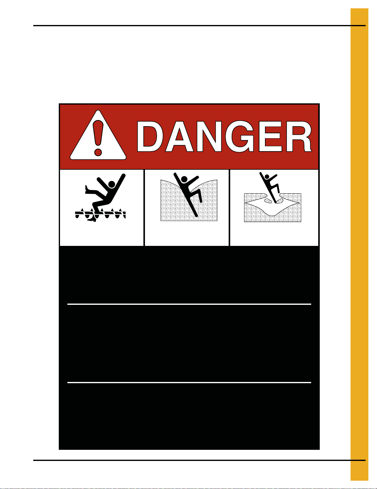
Chapter 2 Decals .................................................................................................................................................... 6
Roof Damage Warning and Disclaimer ................................................................................................. 6
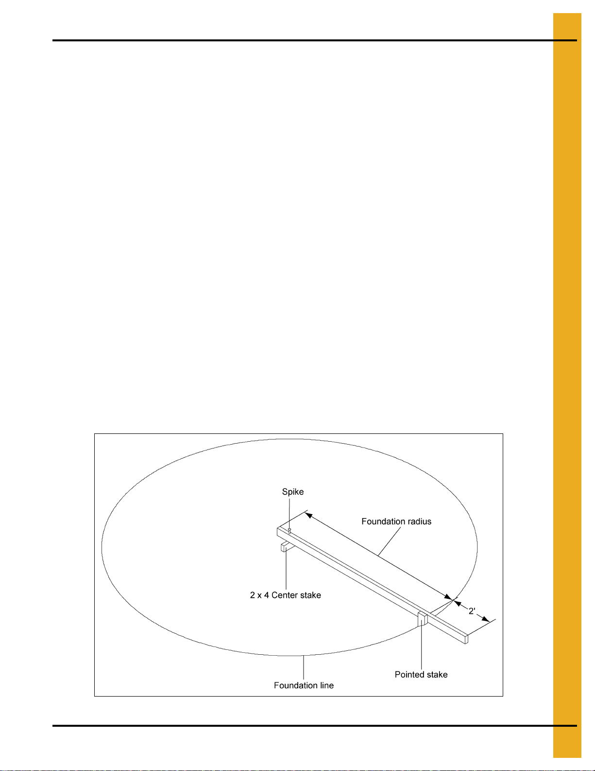
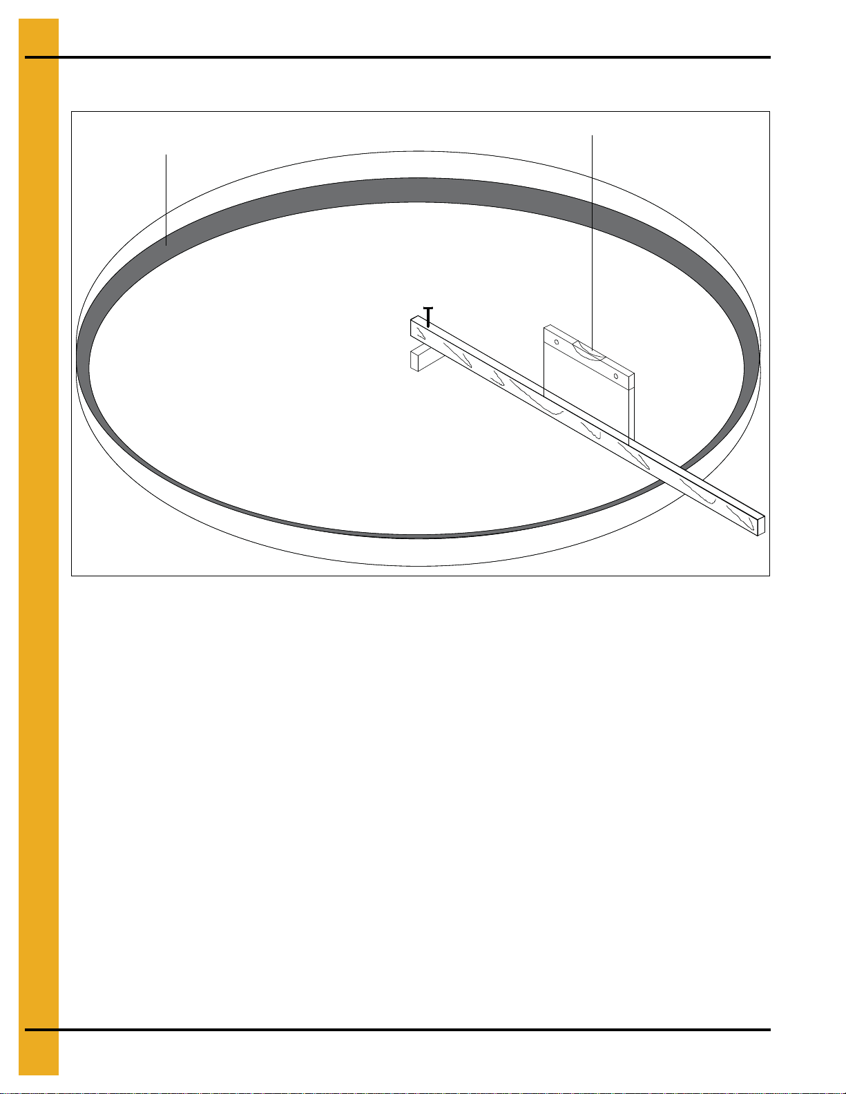
Chapter 3 Foundation Requirements ................................................................................................................... 9
Foundation Requirements for Top Dry Bins (4.00" Top Dry Bin Corrugation) ...................................... 9
Circular Foundation Form ................................................................................................................... 10
Octagonal Foundation Form ............................................................................................................... 11
Inline Centrifugal Fan Pad ................................................................................................................... 12
Duct and Drying Fan Pad Optional ..................................................................................................... 13
Frost Free Foundation Top Dry Bins ................................................................................................... 14
Frost Free Pad .................................................................................................................................... 15
Anchor Bolt Placement ........................................................................................................................ 16
Chapter 4 Hardware ............................................................................................................................................. 17
Hardware/Bolting Requirements ......................................................................................................... 17
Location of Accessories ...................................................................................................................... 20
Very Important ..................................................................................................................................... 21
Chapter 5 Sidewall Construction ........................................................................................................................ 22
Sidewall Gauges ................................................................................................................................. 22
Sidewall Erection Instructions ............................................................................................................. 23
Caulking Detail .................................................................................................................................... 24
Sidewall Construction Instructions ...................................................................................................... 25
Lifting Jacks and Brackets .................................................................................................................. 26
Lifting Jack Usage ............................................................................................................................... 27
Chapter 6 Stiffener Details .................................................................................................................................. 28
Stiffener Gauges ................................................................................................................................. 28
Outside Stiffeners ................................................................................................................................ 29
Top Stiffener Starting Location ............................................................................................................ 31
Stiffener Installation and Location ....................................................................................................... 32
Bolting Requirements Two (2) Stiffeners per Sidewall Sheet ............................................................. 33
Stiffener and Seam Locations ............................................................................................................. 34
Chapter 7 “C” Channels ...................................................................................................................................... 35
Stiffener to “C” Channel Bracket Installation....................................................................................... 35
“C” Channel Installation ....................................................................................................................... 36
Center Collar Assembly ...................................................................................................................... 37
Chapter 8 Installation .......................................................................................................................................... 38
Rafter Installation and Floor Support Angle Attachment ..................................................................... 38
Purlin Installation ................................................................................................................................. 39
Dump Hopper Installation .................................................................................................................... 42
Floor Sheet Installation ....................................................................................................................... 42
24' Leveling Band Post Installation ..................................................................................................... 43
30' Leveling Band Post Installation ..................................................................................................... 44
36' Leveling Band Post Installation ..................................................................................................... 45
Flashing Bolt Installation ..................................................................................................................... 46
Eave Flashing Installation ................................................................................................................... 46
Eave Flashing Splice ........................................................................................................................... 47
Outer Dump Chutes ............................................................................................................................ 48
Intermediate Dump Chutes ................................................................................................................. 49
24' Leveling Band Location ................................................................................................................. 50
30' Leveling Band Location ................................................................................................................. 51
36' Leveling Band Location ................................................................................................................. 53

Table of Contents
4 PNEG-1510 Top Dry 24', 30' and 36' Manual Batch
Chapter 9 Assembly ............................................................................................................................................ 55
Center Cone Assembly ....................................................................................................................... 55
Center Cone Installation ...................................................................................................................... 55
Roof Assembly .................................................................................................................................... 56
Pulley Assembly .................................................................................................................................. 57
Dump Chute Chain Assembly ............................................................................................................. 58
Winch Assembly .................................................................................................................................. 60
Fan Entrance Sheets .......................................................................................................................... 61
Top Dry Access Door Assembly (TD-100996) .................................................................................... 62
Detailed Layout for Proper Location of Platforms ............................................................................... 63
Access Door Platform (TDP-5012) ...................................................................................................... 64
Large Platform Assembly for 42" Fan ................................................................................................. 65
42" Fan Diffuser Instructions and Installation ...................................................................................... 68
Cross Over Platform Assembly (for use with stairs) (TDP-5013) ........................................................ 70
Perforated Center Band ...................................................................................................................... 71
Optional Rotary Switch Roof Locations ............................................................................................... 72
Optional Rotary Switch Panel Locations ............................................................................................. 72
Optional Installation of Roof Mounted Level Switches ........................................................................ 73
Optional Installation of Wall Mounted Rotary Switches ....................................................................... 74
Transition Installation (TR-4734) ......................................................................................................... 75
Transition Assembly (TR-4734) .......................................................................................................... 76
Chapter 10 Accessories ...................................................................................................................................... 77
2 Ring Door Installation Instructions .................................................................................................. 77
2 Ring Door Assembly ....................................................................................................................... 78
Optional Bin Step Assembly (WD-042) ............................................................................................. 80
Base Angle ........................................................................................................................................ 81
Base Stiffener Shim ........................................................................................................................... 81
Chapter 11 Warranty ............................................................................................................................................ 83

PNEG-1510 Top Dry 24', 30' and 36' Manual Batch 5
1. Safety
Safety Guidelines
This manual contains information that is important for you, the owner/operator, to know and understand.
This information relates to protecting personal safety and preventing equipment problems. It is the
responsibility of the owner/operator to inform anyone operating or working in the area of this equipment
of these safety guidelines. To help you recognize this information, we use the symbols that are defined
below. Please read the manual and pay attention to these sections. Failure to read this manual and its
safety instructions is a misuse of the equipment and may lead to serious injury or death.
DANGER
WARNING
CAUTION
NOTICE
This is the safety alert symbol. It is used to alert you
to potential personal injury hazards. Obey all safety
messages that follow this symbol to avoid possible
injury or death.
WARNING indicates a hazardous situation which, if not
avoided, could result in death or serious injury.
CAUTION, used with the safety alert symbol, indicates a
hazardous situation which, if not avoided, could result in
minor or moderate injury.
NOTICE is used to address practices not related to
personal injury.
DANGER indicates a hazardous situation which, if not
avoided, will result in death or serious injury.

6 PNEG-1510 Top Dry 24', 30' and 36' Manual Batch
2. Decals
Roof Damage Warning and Disclaimer
Excessive vacuum (or pressure) may
damage roof. Use positive aeration
system. Make sure all roof vents are
open and unobstructed. Start roof
fans when supply fans are started.
Do not operate when conditions exist
that may cause roof vent icing.
DC-969
CAUTION!
The manufacturer does not warrant any roof damage caused by excessive vacuum or internal
pressure from fans or other air moving systems. Adequate ventilation and/or “makeup air”
devices should be provided for all powered air handling systems. The manufacturer does not
recommend the use of downward flow systems (suction). Severe roof damage can result from
any blockage of air passages. Running fans during high humidity/cold weather conditions can
cause air exhaust or intake ports to freeze.

2. Decals
PNEG-1510 Top Dry 24', 30' and 36' Manual Batch 7
ATTENTION: The decal shown below should be present on the outside of the door cover of the 2 ring,
24" porthole door cover and the roof manway cover. If a decal has been damaged or is missing in any of
these locations, contact the manufacturer for a free replacement decal.
GSI Decals
1004 E. Illinois St.
Assumption, IL. 62510
Phone: 1-217-226-4421
Rotating flighting will
kill or dismember.
Flowing material will
trap and suffocate.
Crusted material will
collapse and suffocate.
Keep clear of all augers.
DO NOT ENTER this bin!
Failure to heed these
warnings will result in
serious injury or death.
If you must enter the bin:
1. Shut off and lock out all power.
2. Use a safety harness and safety line.
3. Station another person outside the bin.
4. Avoid the center of the bin.
5. Wear proper breathing equipment or respirator.
DC-GBC-1A

2. Decals
8PNEG-1510 Top Dry 24', 30' and 36' Manual Batch
ATTENTION: The decal shown below should be present on the outside of the door cover of the 2 ring,
24" porthole door cover and the roof manway cover. If a decal has been damaged or is missing in any of
these locations, contact the manufacturer for a free replacement decal.
GSI Decals
1004 E. Illinois St.
Assumption, IL. 62510
Phone: 1-217-226-4421
Failure to heed these warnings
could result in serious injury, death,
structural damage or collapse of tank.
1. Use CENTER FLOOR OUTLET ONLY until NO grain
remains above this outlet.
2. Side floor outlets to be used ONLY when above
condition is satisfied.
3. Lock all side floor outlets to avoid accidental
premature use.
4. See manufacturers instructions for proper use of
factory supplied sidedraw (wall) discharge systems.
UNLOADING INSTRUCTIONS:
DC-GBC-2A
WARNING
DON’T DO

PNEG-1510 Top Dry 24', 30' and 36' Manual Batch 9
3. Foundation Requirements
Foundation Requirements for Top Dry Bins (4.00" Top Dry
Bin Corrugation)
Requirements
The following foundation recommendations are a revision to earlier manuals distributed by the
GSI Group.
NOTE: There are changes in foundation dimensions from past publications. These dimensions are critical
to the proper installation and function of each foundation.
Selecting the Proper Site
The selected site should be level, firm and free from underlying debris. The bin can be installed
satisfactorily on slopes, but as the slope increases, additional labor and materials are required for the
foundation. The concrete foundation surface must be level. If some fill is required, it should be watered
and tamped thoroughly to prevent uneven settling from the weight of the bin. Naturally, the site must allow
convenient access for easy loading and unloading, plus provide additional space for future units. Also
considerthepositioningofhandlingequipment,availabilityofelectricityandtheplacementoffans,heaters
and gas tanks.
Scribe the Diameter
Having determined the center of the site, drive a small 2 x 4 in the ground to mark the center point of the
foundation. The top of the stake should be the same height as the finished foundation will be. Using one
large spike, nail a straight 2 x 4 (approximately 2' longer than the radius of the bin) to the top of the center
spike. The swiveling 2 x 4 will act as a compass, enabling you to scribe the correct diameter of the
foundation and later locate the anchor and stiffener bolt locations. (NOTE: Making the 2 x 4 2' longer than
the radius allow the 2 x 4 to also be used as a leveling device and for pulling concrete.) (See Figure 3A.)
Figure 3A

3. Foundation Requirements
10 PNEG-1510 Top Dry 24', 30' and 36' Manual Batch
Circular Foundation Form
Figure 3B
Prepare the Foundation
Having scribed the diameter of the foundation, proceed by digging the footing of the foundation. This
consists of a large circular trench dug just inside the foundation line. (Refer to foundation details for
necessary information.) Once the footing has been dug, you are ready to build the forms. It is important
that the form be rigid enough to hold its shape against the poured concrete. Also, the foundation must be
flat. Sloped floors cannot be used in drying bins. A carpenter’s level placed on top of the 2 x 4 will enable
you to set the top of the forms to match the top of the center stake. Check the form work with a transit to
ensure a uniform elevation for the entire foundation. (See Figure 3B.)
Footing trench
Carpenter’s level

3. Foundation Requirements
PNEG-1510 Top Dry 24', 30' and 36' Manual Batch 11
Octagonal Foundation Form
There are two (2) styles of foundation forms commonly used. The first is the circular form depicted in
Figure 3B on Page 10. The second style can be made of 2" x 8" boards set into a square with corners
blocked off to form an octagon. (See Figure 3C.) This eight (8) sided form will approximate a circle and
can be constructed quite easily.
When the foundation form is completed install reinforcement rods by either welding or wiring in place.
Place 2" of compacted sand on the inside level of the foundation. The sand is then covered with a 4 mil
plastic moisture barrier. 6" x 6" Wire mesh (two (2) mats), covering the entire area of the foundation,
completes the preparation of the bin’s foundation. You are now ready to begin pouring concrete.
NOTE: All concrete is to have a minimum compressive strength of 3000 PSI at 28 days.
Figure 3C

3. Foundation Requirements
12 PNEG-1510 Top Dry 24', 30' and 36' Manual Batch
Inline Centrifugal Fan Pad
Placement of the Fan Pad: GSI Transitions/Fans only.
If a fan is to be installed, refer to Figure 3D to determine the concrete pad size.
1. The top of this pad should be level with the top of the bin’s foundation.
2. Recommended pad thickness is 4" minimum.
3. Front of pad should be perpendicular to bin wall.
4. Pad for heater not required.
IMPORTANT: Fan pad and fan must be leveled and smooth for proper operation. Vibration problems can
result from improper fan leveling.
Figure 3D

3. Foundation Requirements
PNEG-1510 Top Dry 24', 30' and 36' Manual Batch 13
Duct and Drying Fan Pad Optional
Placement of the Duct Fan Pad: GSI Top Dry Duct System only.
Refer to Figure 3E to determine the duct pad size.
1. The top of this pad should be level with the top of the bin’s foundation.
2. Recommended pad thickness is 4" minimum.
3. Front of pad should be perpendicular to bin wall.
Figure 3E

3. Foundation Requirements
14 PNEG-1510 Top Dry 24', 30' and 36' Manual Batch
Frost Free Foundation Top Dry Bins
Diameter of Bin: 24'
Corrugation : 4.00"
Ring # B N Outside
Radius Sq. Ft. Mesh
6 x 6 - 6/6 Optional #4
18" x 18" Grid (Ft.) Length#6
Bar (Ft.) Total Cu. Yds.
Concrete
61'-1" 212'-9" 900 600 200 13
7, 8 1'-9" 2 12'-9" 900 600 200 15
9, 10 2'-6" 313'-2" 900 600 400 18
Diameter of Bin: 30'
Corrugation : 4.00"
Ring # B N Outside
Radius Sq. Ft. Mesh
6 x 6 - 6/6 Optional #4
18" x 18" Grid (Ft.) Length#6
Bar (Ft.) Total Cu. Yds.
Concrete
61'-2" 215'-9" 1400 900 200 19
7, 8 1'-10" 2 15'-10" 1400 900 200 21
9, 10 2'-8" 316'-1" 1400 900 500 25
11 3'-8" 4 16'-5" 1400 900 700 29
Diameter of Bin: 36'
Corrugation : 4.00"
Ring # B N Outside
Radius Sq. Ft. Mesh
6 x 6 - 6/6 Optional #4
18" x 18" Grid (Ft.) Length#6
Bar (Ft.) Total Cu. Yds.
Concrete
61'-3" 218'-9" 2000 1300 300 26
7, 8 2'-0" 2 18'-11" 2000 1300 400 30
9, 10 2'-10" 319'-0" 2000 1300 600 33
11, 12 3'-11" 4 19'-6" 2000 1300 900 39

3. Foundation Requirements
PNEG-1510 Top Dry 24', 30' and 36' Manual Batch 15
Frost Free Pad
NOTES:
1. Foundation site should be well drained and free of vegetation or debris.
2. Foundation design is based on a minimum soil bearing capacity of 3000 lbs/ft2. If soil bearing
capacity is in doubt, contact a local soil testing engineer.
3. Concrete shall have a minimum compressive strength of 3000 PSI at 28 days.
4. Requirements for reinforcement do not include overlap.
5. Lap all circumferential bars 35 bar diameters and stagger all laps in plan 3'-0".
6. All material used for backfill inside the ring wall should be a clean, well graded, crushed stone or
sand-gravel mixture. Backfill should be placed in 6" lifts and well compacted.
Figure 3F

3. Foundation Requirements
16 PNEG-1510 Top Dry 24', 30' and 36' Manual Batch
Anchor Bolt Placement
Having poured and leveled the concrete, use the center stake and straight 2" x 4" again to find the bolt
circle radius for the outside hold-down brackets. Select a starting point and stretch a pre-measured chord
along the imaginary circle formed by the bolt circle radius. Take into consideration the placement of these
bolts so as not to interfere with the positions of bin doors and transitions. (Refer to below Chart for
necessary radius and chord lengths.) Take the time and work carefully since accuracy is important.
Work both directions from first anchor bolt location, this will help eliminate possible error in laying out
anchor bolts. On larger bins sight across starting anchor bolt and center pin and place anchor bolt on
opposite side of anchor bolt radius. From this point you can work both directions from both anchor bolts.
NOTE: Top edge of slab where the bin wall sets must be held to within 1/8" of level.
Figure 3G Anchor Bolt
Bin
Diameter “B” Bolt
Circle Radius # of
Anchors “E” Chord
Distance
24' 12' - 2-7/8" 16 4' - 9-5/16"
30' 15' - 2-11/16" 20 4' - 9-1/8"
36' 18' - 2-1/2" 24 4' - 9-1/16"

PNEG-1510 Top Dry 24', 30' and 36' Manual Batch 17
4. Hardware
Hardware/Bolting Requirements
IMPORTANT: Do not tighten bolts to exceed the torque specifications listed below.
IMPORTANT: Hardware Usage - 20 Gauge - 15 gauge sidewall sheets, use 5/16" x 3/4" bolts and
nuts (S-275).
14 Gauge and 13 gauge sidewall sheets, use 5/16" x 3/4" bolts and
nuts (S-275).
Use 5/16" x 1-1/4" (S-277) for attaching floor flashing to the sidewall.
Bolt Size Torque (Ft. lbs.)
Minimum Maximum
5/16"-18 15 20
3/8"-16 35 42
7/16"-14 65 72
1/2"-13 95 105
NOTE: Grade 2 bolts are designated with a plain head.
NOTE: Grade 5 bolts are designated by three (3) slash marks on the head.
All 5/16" diameter bolts are to be grade 5 or higher.
NOTE: Grade 8 bolts are designated by six (6) slash marks on the head.
NOTE: Grade 8.2 bolts are designated by six (6) slash marks on the head in a
sunrise pattern.
All 3/8" diameter bolts are to be grade 8 or 8.2.
Under no condition shall any other bolts be substituted for those supplied by
GSI Group.
CAUTION

4. Hardware
18 PNEG-1510 Top Dry 24', 30' and 36' Manual Batch
Refer to Top Dry Tank Bolting Requirements for Complete Bolt Usage
0.3125" x 0.750" Pre-assembled with a steel backed neoprene washer.
This bolt is used to connect horizontal and vertical seams for 13 gauge and thinner sidewall sheets
to each other and to bolt the stiffeners to the sidewall sheets. It is also used in attaching roof panels
to the top sidewall sheet and attaching roof panels and flashing to the center collar.
0.3125" x 1.250" Pre-assembled with a steel backed neoprene washer.
This bolt is primarily used to connect roof panels together where they overlap. It is also used at the
bottom of the flat bottomed bins to attach the base angle to the sidewall sheet. A small number of
these are provided for joints and FC-42076 splice plates for the stiffeners to sidewall connection.

4. Hardware
PNEG-1510 Top Dry 24', 30' and 36' Manual Batch 19
Refer to Top Dry Tank Bolting Requirements for Complete Bolt
Usage (Continued)
NOTE: Theonlywashersshippedloose with the binsarethesteel flat washers. The 5/16" steelflatwasher
(S-845) is used where the base angle attaches to the sheet and some are used at the main eave
clips. The 3/8" steel flat washers (S-248) are used at the stiffener splices and some are used in
the roof rafter splices.
0.375" x 1.000" Hex flanged head without a plastic sealing washer.
This bolt is used to splice the stiffeners together on the flanges. A steel flat washer is used on the
nut side of the connection. They are also used on “C” channel splices and mounting “C” channel to
wall bracket.
0.375" x 1.500" Hex flanged head without a plastic sealing washer.
This bolt is used to attach the wall bracket to the sidewall and stiffener. A steel flat washer is used
on the nut side of the connection.

4. Hardware
20 PNEG-1510 Top Dry 24', 30' and 36' Manual Batch
Location of Accessories
Below is a typical Top Dry bin layout showing suggested locations of Top Dry accessories. When locating
the manway be sure the outside ladder will not interfere with other accessories below. Roof vents should
be spaced evenly around the roof. (Quantity will vary with individual systems.) (See Figure 4A.)
NOTE: The Top Dry system should be provided with a dependable equipment ground.
Figure 4A
This manual suits for next models
2
Table of contents
Other GSi Storage Bin manuals

GSi
GSi JS500 User manual

GSi
GSi 40 Series Instructions for use

GSi
GSi 40 Series Instructions for use

GSi
GSi Beta 40 Series User manual

GSi
GSi 40 Series Instructions for use

GSi
GSi 40 Series Instructions for use

GSi
GSi 40 Series Instructions for use

GSi
GSi 40 Series Instructions for use

GSi
GSi 40-SERIES Instructions for use