manuals.online logo
Brands
  1. Home
  2. •
  3. Brands
  4. •
  5. Guard master
  6. •
  7. Switch
  8. •
  9. Guard master PROSAFE RPSE Series User manual

Guard master PROSAFE RPSE Series User manual

1
Einbauanleitung
(b) Installation Instructions Notice d'installation
Deutch /
Français
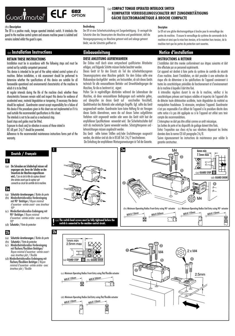
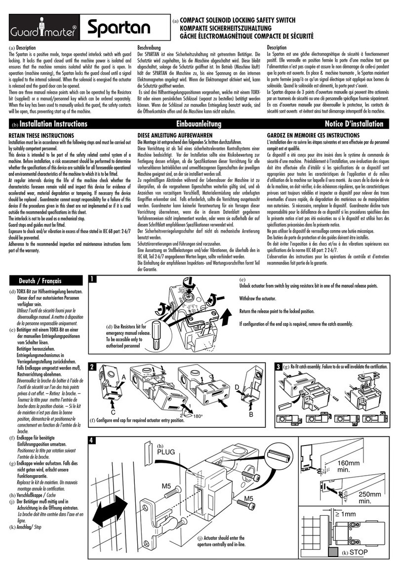
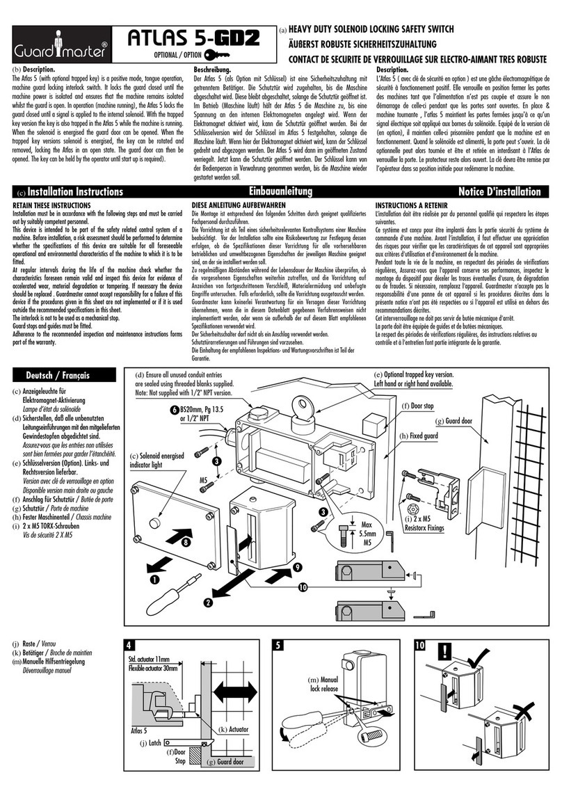
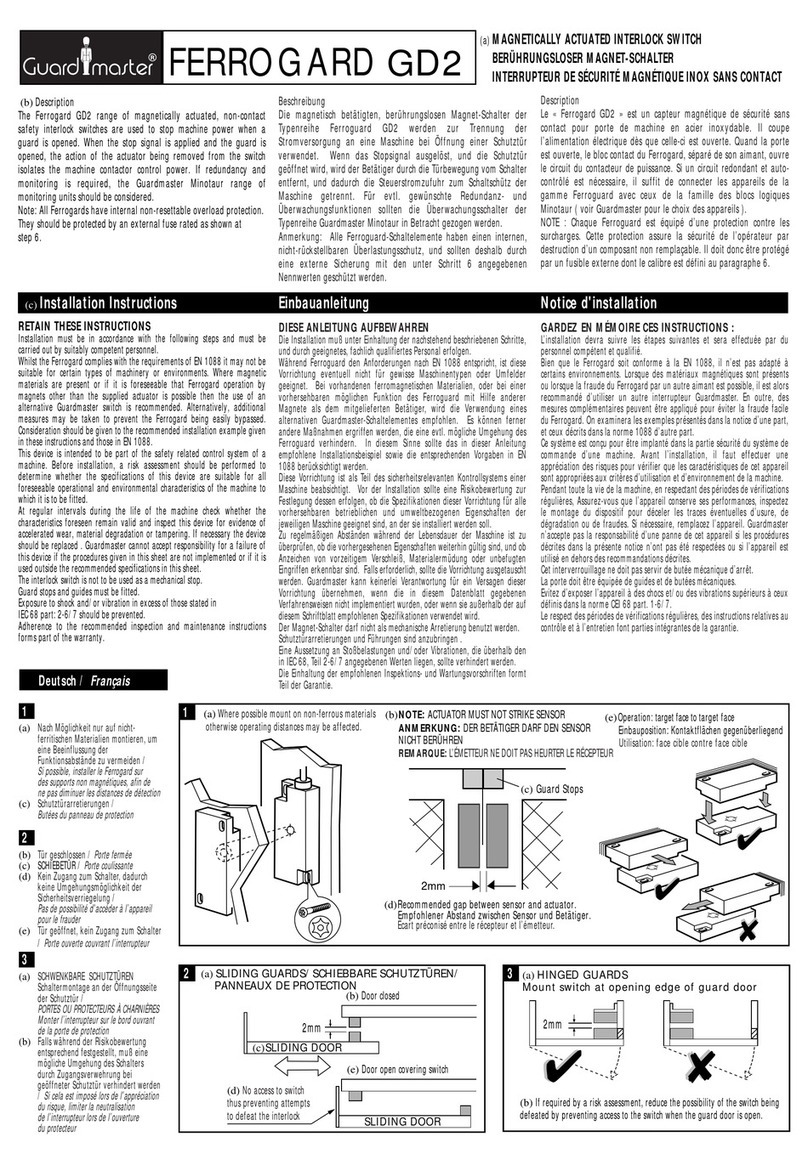
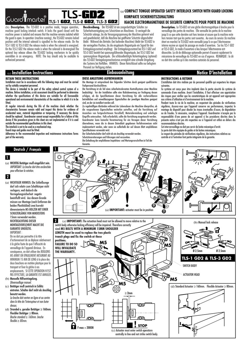
(a) Description
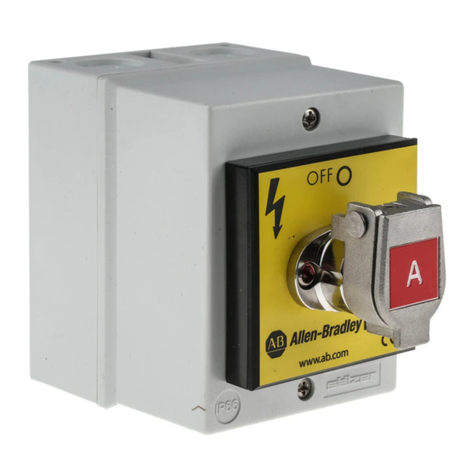
The Prosafe rotary key switch is a trapped key unit that isolates power when the
coded trapped key is removed. The key can only be romoved by rotating 90°
anti-clockwise which in turn changes the state of the switch contacts. Re-
insertion of the correct key and rotation 90°clockwise reverts the contacts to
the original state, and trapping the key in the unit.
Beschreibung
Der Prosafe ist ein Drehschalter mit Schlüsselarretierung, der bei
Abziehen des arretierten und codierten Schlüssels den Strom abschaltet.
Der Schlüssel kann nur nach einer Drehung von 90°entgegen dem
Uhrzeigersinn abgezogen werden, mit der gleichzeitig die Stellung der
Schaltkontakte geändert wird. Erneutes Einstecken des korrekten
Schlüssels und eine Drehung von 90°im Uhrzeigersinn versetzt die
Kontakte wieder in ihre ursprüngliche Stellung, und arretiert den
Schlüssel.
Description
La clé de sécurité Prosafe est un dispositif à clé verrouillée qui coupe
l’alimentation lorsqu’on enlève la clé verrouillée à code. On ne peut
enlever cette clé qu’en la tournant d’un quart de tour (90°) dans le sens
inverse des aiguilles d'une montre, en modifiant ainsi l’état des contacts
de l’interrupteur. En replaçant la clé correcte et en la tournant dans le
sens horaire d’un quart de tour (90°), on rétablit les contacts d’origine,
en verrouillant la clé dans l’appareil.
RETAIN THESE INSTRUCTIONS
Installation must be in accordance with the following steps and must be
carried out by suitably competent personnel.
This device is intended to be part of the safety related control system. Before
installation, a risk assessment should be performed to determine whether the
specifications of this device are suitable for all foreseeable operational and
environmental characteristics of the machine to which it is to be fitted.
At regular intervals during the life of the unit check whether these
characteristics foreseen remain valid and inspect this device for evidence of
accelerated wear, material degradation or tampering. If necessary the device
should be replaced. The manufacturer cannot accept responsibility for a failure
of this device if the procedures given in this sheet are not implemented or if it
is used outside the recommended specifications in this sheet.
Adherence to the recommended maintenance instructions forms part of the
warranty.
DIESE ANLEITUNG AUFBEWAHREN
Die Installation muß unter Einhaltung der nachstehend beschriebenen
Schritte, und durch geeignetes, fachlich qualifiertes Personal erfolgen.
Diese Vorrichtung ist als Teil des sicherheitsrelevanten Kontrollsystems
beabsichtigt. Vor der Installation sollte eine Risikobewertung zur Festlegung
dessen erfolgen, ob die Spezifikationen dieser Vorrichtung für alle
vorhersehbaren betrieblichen und umweltbezogenen Eigenschaften der
Maschine geeignet sind, an der sie installiert werden soll.
Zu regelmäßigen Abständen während der Lebensdauer der Baugruppe ist zu
überprüfen, ob die vorgesehenen Eigenschaften weiterhin gültig sind, und
ob Anzeichen von vorzeitigem Verschleiß, Materialermüdung oder
unbefugten Eingriffen erkennbar sind. Falls erforderlich, sollte die
Vorrichtung ausgetauscht werden. Der Hersteller kann keinerlei
Verantwortung für ein Versagen dieser Vorrichtung übernehmen, wenn die in
diesem Datenblatt gegebenen Verfahrensweisen nicht implementiert
wurden, oder wenn sie außerhalb der auf diesem Schriftblatt empfohlenen
Spezifikationen verwendet wird.
Die Einhaltung der empfohlenen Wartungsvorschriften formt Teil der
Garantie.
CONSERVEZ CES INSTRUCTIONS
L’installation doit être effectuée par du personnel qualifié qui respectera les
étapes suivantes.
Ce système est conçu pour être implanté dans la partie sécurité du système
de commande. Avant l’installation, il faut effectuer une appréciation des
risques pour vérifier que les caractéristiques de cet appareil sont appropriées
aux critères d’utilisation et d’environnement de la machine.
Pendant toute la vie de la machine, en respectant des périodes de vérification
régulières, assurez-vous que l’appareil conserve ses performances, inspectez
le montage du dispositif pour déceler des traces éventuelles d’usure, de
dégradation ou de fraudes. Si nécessaire, remplacez l’appareil. Le fabricant
n'accepte pas la responsabilité pour des pannes éventuelles de cet appareil si
les procédures décrites dans la présente notice n’ont pas été respectées ou si
l’appareil est utilisé en dehors des recommandations dans la présente.
Le respect des instructions relatives à l’entretien recommandé font partie
intégrante de la garantie.
INTERRUPTEUR DE SÉCURITÉ POUR MONTAGE TABLEAU - RPSE
ROTARY KEY SWITCH - RPSE
HAUPTSCHALTER - RPSE
ACCESS KEYS TRAPPED.
KEY TRAPPED
ELECTRICAL
SUPPLY ON B
Machine is running - Electrical supply is
ON - All access doors are locked.
ELECTRICAL
SUPPLY
LOCKED OFF
ACCESS KEYS FREE.
ELECTRICAL ISOLATION KEY TRAPPED.
A
A
BB
B
Machine is now stopped - Electrical supply
is isolated - Access doors can now be opened
- When Doors are open, keys are trapped.
A
Machine is now stopped -
Electrical supply is isolated -
Door can now be opened -
With door open Key A is trapped -
Key B is taken into guarded area to
ensure the door cannot be locked by
a third party.
B
A
A
A
KEY TRAPPED
ELECTRICAL
SUPPLY ON
Machine running
- Electrical supply
ON - Access door
Locked.
B
M4 (2 off)
Mounting Plate
2
32
16
2 HOLES Ø4HOLE Ø20
PANEL MOUNTING DETAILS
5mm MAX
Line-up code barrel with
housing as shown. Code
barrel should not rotate
in housing.
MOUNTING / MONTAGE / MONTAGE
PART BODY ACCESS FULL BODY ACCESS
(c) ANWENDUNGSBEISPIELE /
Exemples
d’application
(d) TEILWEISER KÖRPERLICHER ZUGANG /
ACCES AU CORPS DE LA PIECE
(e) SCHLÜSSEL ARRETIERT, STROMVERSORGUNG EIN /
CLÉ VERROUILLÉE - MACHINE SOUS TENSION
(f) ZUGANGSSCHLÜSSEL ARRETIERT /
CLÉS D’ACCES VERROUILLÉES
(g) Maschine läuft - Stromversorgung EIN -
Alle Zugangstüren sind verriegelt /
La machine
est en marche - La machine est sous tension -
Toutes les portes d’accès sont verrouillées
(h) STROMVERSORGUNG DURCH SCHLÜSSEL
GESPERRT /
ALIMENTATION ELECTRIQUE
BLOQUEE HORS CIRCUIT
(i) ZUGANGSSCHLÜSSEL FREI-SCHLÜSSEL FÜR
ELEKTRISCHE TRENNUNG ARRETIERT /
CLÉS
D’ACCES LIBRES - CLÉ DE COUPURE DE
L’ALIMENTATION ELECTRIQUE VERROUILLÉE
(j) Maschine steht jetzt still - Die Stromversorgung ist
getrennt - Zugangstüren können jetzt geöffnet
werden - Bei geöffneter Tür werden die
Schlüssel arretiert. /
La machine est maintenant
arrêtée - L’alimentation électrique est coupée - On
peut ouvrir les portes d’accès - Lorsque les portes
sont ouvertes, les clés sont verrouillées
(k) VOLLER KÖRPERLICHER ZUGANG /
ACCES INTEGRAL AU CORPS
(l) Maschine läuft - Stromversorgung EIN -
Zugangstür verschlossen. /
La machine est en
marche - La machine est sous tension - Toutes les
portes d’accès sont verrouillées
(m) Maschine steht jetz still - Die Stromversorgung ist
getrennt - Die Tür kann jetzt geöffnet werden -
Bei geöffneter Tür wird Schlüssel A arretiert
- Schlüssel B wird in einem bewachten
Bereich aufbewahrt, um sicherzustellen, daß
die Tür nicht durch eine dritte Person
verschlossen werden kann. /
La machine est
maintenant arrêtée - L’alimentation électrique est
coupée - On peut ouvrir la porte - Lorsque la porte
est ouverte, la clé A est bloquée - La clé B est
placée dans une zone surveillée afin d’assurer que
la porte ne puisse pas être verrouillée par des tiers
(d)
(e)
(f)
(h)
(g)
(i)
(j)
ELECTRICAL
SUPPLY
LOCKED OFF
(h)
(e)
(m)
(l)
(k)
(b) Den Code-Zylinder wie abgebildet mit dem
Gehäuse ausrichten. Der Code- Zylinder darf
sich im Gehäuse nicht drehen /
Alignez le
barillet codé de la serrure et le boîtier, de la façon
représentée. Ne tournez pas le barillet codé dans
le boîtier
(c) Montageplatte /
Plaque de montage
(d) Codierter Schlüssel /
Clé codée
(e) Code-Zylinder /
Barillet codé
(f) Nomenklaturschild /
Plaque de légende
(g) Isolator /
Isolateur
(h) SCHALTTAFEL-MONTAGEDIMENSIONEN /
ILLUSTRATION DU MONTAGE DU PANNEAU
1
(b) (c)
(h)
(a)
(c)
APPLICATION EXAMPLES
Coded Key(d)
Code Barrel Assembly(e)
Legend Plate(f)
Isolator(g)
PROSAFE
4(a) WIRING / VERDRAHTUNG / CÂBLAGE
All types excluding RPS 11
4 N/O shown with key free
(b) RPS11 type
2 N/O + 2 N/C shown with key free
(c)
5(a) OPERATION / BEDIENUNG / UTILISATION
Check for correct operation.
Ensure power is isolated when the key is free.
Upon correct installation, fixing screws should
be coated with a tamper evident varnish or
similar compound.
Key 'C' Rotated and Free, Power Off.
Key 'C' Trapped, Power On.
Adjust Position of Flip Cap if Required
Loosen grub screw
in cap
Rotate cap and
tighten grubscrew
3(a) ASSEMBLY / MONTAGE / MONTAGE
M4 (2 off)
(d)
(c)
(b)
Deutch /
Français
(b) Falls erforderlich, Position der
Schutzklappe justieren /
Ajustez la
position du chapeau basculant, si nécessaire
(c) Gewindestift in der Klappe lösen /
Desserrez la vis sans tête dans le chapeau
(d) Klappe rotieren, und Gewindestift
festziehen /
Tournez le chapeau et serrez
la vis sans tête
(e) Wenn Sie es befestigt haben versiegeln
Sie diese mit Sicherheitslack. /
Quand
l'assemblage est correct, bloquer avec un
vernis ou un composant similaire.
3
(b) Alle Typen außer RPS 11 abgebildet: 4
Schließer mit Schlüssel frei (abziehbar)
/
Tous les types RPS11 exclu
4 N/O représenté avec clé libre
(c) Typ RPS 11
abgebildet: 2 Schließer + 2 Öffner mit
Schlüssel frei (abziehbar) /
Type RPS11
2 N/O + 2 N/F représentés avec clé libre
4
(b)
(c)
(d)
(b) Korrekte Funktion prüfen.
Sicherstellen, daß der Strom getrennt ist,
wenn der Schlüssel frei ist. Nach der
vorschriftsmäßigen Installation, die
Einbauschrauben mit Farblack o.ä. zur
Erkennung unbefugter Eingriffe
versiegeln /
Vérifiez que l’appareil
fonctionne correctement.
Vérifiez que l’alimentation est coupée
lorsque la clé est libre. Après avoir
effectué l’installation correctement,
appliquer une couche de vernis infraudable
ou produit similaire sur les vis de fixation
(c) Schlüssel ‘C’ gedreht und frei, Strom AUS
/
Clé ‘C’ tournée et libre: alimentation
coupée
(d) Schlüssel ‘C’ arretiert, Strom EIN /
Clé ‘C’ verrouillée: appareil sous tension
5
1 2
3 4
5 6
7 8
1 2
3 4
5 6
7 8
(e)
When fitted coat with
tamper evident varnish
or similar compound
UNITS SHOULD BE
INSTALLED WITH FLIP CAP
HINGE UPPERMOST
Deutsch /
Français
Technical Specifications
Conforming to standard EN 292, EN 1088,
IEC 947-5-1, GS-ET -19
Contacts
all types except RPS11 4 N/O
type RPS11 2 N/O + 2 N/C
Rating IP20
Finger protection DIN 57106/VDE 0106 T.100
Ambient temp. -10°C to +40°C
Mechanical operations 1 x 10⁵
Max. shear force to key 15.1kN
Max. torque to key 14Nm
Relative operating humidity 25% to 95%
Weight 0.85kg
Code barrels Tested to 1,000,000 operations
Isolator approved SA, S, S+, UL, D, Fl
Electrical operations >105
Climatic test Constant to DIN IEC 68 Part 2-3
Variable to DIN IEC 68 Part 2-30
Ambient temp. Encased -25°C to +40°C
Rtd. insulation voltage (Ui) 690V
Rtd. impulse withstand vol. (Uimp) 6kV
S3 intermittent rating (VDE 0530
Part 1) duty factor 60/40/25%=1,3/1,6/2xlu
Rtd. uninterrupted current (Iu)
IEC/EN/VDE 20A 32A 63A 100A
UL/CSA 16A 30A 60A 100A
Rtd. operational voltage (Ue)
IEC/EN/VDE 690V 690V 690V 1000A
UL/CSA 600V 600V 600V 600V
Main switch isol. voltage up to 750V 750V 750V 1000V
Rtd. operational current (Ie)
AC-21A IEC/EN/VDE 20A 32A 63A 100A
AC-1 SEV 20A 32A 63A 100A
Rtd. operational power at 50 to 60Hz
AC-23A IEC/EN/VDE
3 phase 220-240V 4kW 7.5kW 15kW 22kW
3 pole 380-440V 7.5kW 15kW 30kW 37kW
500-690V 7.5kW 11kW 30kW 37kW
AC-3 IEC/EN/VDE
3 phase 220-240V 3kW 5.5kW 11kW 22kW
3 pole 380-440V 5.5kW 11kW 22kW 37kW
500-690V 5.5kW 11kW 22kW 30kW
DOL-rating UL/CSA
3 phase 120V 1.5HP 3HP 5HP 7.5HP
3 pole 240V 3HP 10HP 15HP 30HP
480V 7.5HP 20HP 30HP 50HP
600V 10HP 20HP 40HP 50HP
Rated breaking capacity
AC-23/AC-3 220-240V 250A 330A 500A 600A
Motor switch 380-440V 250A 330A 500A 600A
500-690V 150A 220A 270A 300A
Max. fuse size (gL) 25A 35A 63/50A 100A
Rated fuse short circuit current 15kA 15kA 15/25kA 25kA
Terminal cross section
Single/multiple wire min. mm21 1 4 2.5
max. mm210 10 16 3.5
Fine strand wire min. mm20.75 0.75 2.5 1.5
with sleeve max. mm26 6 10 25
American wire guage 8 8 6 2
Spécifications techniquesTechnische Daten
(r)
(d)
(a) DIMENSIONS / ABMESSUNGEN / DIMENSIONS
(b) SCHUTZKLAPPE /
CHAPEAU DE
PROTECTION
(c) CODE-ZYLINDER /
BARILLET A CODE
(d) MAX. WANDSTÄRKE 5 mm /
EPAISSEUR
MAXIMALE DU PANNEAU: 5 mm
(e) NOMENKLATURSCHILD /
PLAQUE DE
LEGENDE
(f) MONTAGESCHRAUBEN /
VIS DE
FIXATION
(g) SCHALTEREINHEIT /
INTERRUPTEUR
64
64
64 SWITCH UNIT
CODE BARREL 5mm MAX PANEL THICKNESS
WEATHER CAP ASSY
LEGEND PLATE
FIXING SCREWS
(b) (c)
(e)
(f) (g)
OFF
ON
68
Konformität mit folgenden Normen EN 292, EN 1088,
IEC 947-5-1, GS-ET -19
Kontakte
alle Typen außer RPS11 4 Schließer
Typ RPS11 2 Schließer + 2 Öffner
Schutzklasse IP20
Fingerschutz DIN 57106 / VDE 0106 T.100
Umgebungstemperatur -10 °bis +40 °C
Mechanische Lebensdauer 1 x 10⁵Schaltspiele
Max. Schlüssel-Scherkraft 15,1 kN
Max. Schlüssel-Drehmoment 14 Nm
Relative Luftfeuchtigkeit für Betrieb 25% bis 95%
Gewicht 0,85 kg
Code-Zylinder auf 1.000.000 Schaltspiele getestet
Isolator-Zulassung durch SA, S, S+, UL, D, Fl
Elektrische Schaltspiele > 105
Klimatest Konstant nach DIN IEC 68, Teil 2-3
Variabel nach DIN IEC 68, Teil 2-30
Umgebungstemperatur (eingebaut) -25 °bis + 40 °C
Bemessungs-Isolationsspannung (Ui)690 V
Bemessungs-Stoßspannung (Uimp) 6 kV
S3-Aussetzleistung (VDE 0530, Teil 1),
relative Einschaltdauer 60 / 40 / 25% = 1,3 / 1,6 / 2xlu
Bemessungs-Dauerstrom (Iu)
IEC / EN / VDE 20 A 32 A 63 A 100 A
UL / CSA 16 A 30 A 60 A 100 A
Bemessungs-Betriebsspannung (Ue)
IEC / EN / VDE 690 V 690 V 690 V 1000 A
UL / CSA 600 V 600 V 600 V 600 V
Max. Hauptschalter-Isolationsspannung 750 V 750 V 750 V 1000 V
Bemessungs-Betriebsstrom (Ie)
AC-21 A IEC / EN / VDE 20 A 32 A 63 A 100 A
AC-1 SEV 20 A 32 A 63 A 100 A
Bemessungs-Betriebsstrom bei
50 bis 60 Hz
AC-23 A IEC / EN / VDE
3-phasig 220-240 V 4 kW 7,5 kW 15 kW 22 kW
3-polig 380-440 V 7,5 kW 15 kW 30 kW 37 kW
500-690 V 7,5 kW 11 kW 30 kW 37 kW
AC-3 IEC / EN / VDE
3-phasig 220-240 V 3 kW 5,5 kW 11 kW 22 kW
3-polig 380-440 V 5,5 kW 11 kW 22 kW 37 kW
500-690 V 5,5 kW 11 kW 22 kW 30 kW
Direktstart-Bemessungswerte nach
UL / CSA
3-phasig 120 V 1,5 PS 3 PS 5 PS 7,5 PS
3-polig 240 V 3 PS 10 PS 15 PS 30 PS
480 V 7,5 PS 20 PS 30 PS 50 PS
600 V 10 PS 20 PS 40 PS 50 PS
Bemessungs-Ausschaltleistung
AC-23/AC-3 220-240 V 250 A 330 A 500 A 600 A
Motorschalter 380-440 V 250 A 330 A 500 A 600 A
500-690 V 150 A 220 A 270 A 300 A
Max. Sicherungsgröße (gL) 25 A 35 A 63/50 A 100 A
Bem. Sicherungs-Kurzschlußstrom 15 kA 15 kA 15/25 kA 25 kA
Klemmenquerschnitt
Einzel-/Mehrfachkabel min. mm21 1 4 2,5
max. mm210 10 16 3,5
Feinadriges Kabel min. mm20,75 0,75 2,5 1,5
mit Muffe max. mm26 6 10 25
Amerikanisches Drahtmaß 8 8 6 2
Conforme aux normes suivantes EN 292, EN 1088,
IEC 947-5-1, GS-ET -19
Contacts
Tous les types hormis RPS11 4 N/O
RPS11 2 N/O + 2 N/F
Protection IP20
Protection des doigts DIN 57106/VDE 0106T.100
Temp. ambiante -10°C à +40°C
Opérations mécaniques 1 x 10⁵
Force de cisaillement maxi sur la clé 15.1 kN
Couple maxi sur la clé 14 Nm
Humidité relative en service 25% à 95%
Poids 0,85 kg
Barillets codés Testés jusqu’à 1 000 000 opérations
Homologation de l’isolateur SA, S, S+, UL, D, Fl
Actionnements électriques >105
Essais climatiques Constant conf. DIN IEC 68 part. 2-3
Variable conf. DIN IEC 68 part. 2-30
Temp. ambiante -10°C à +40°C en boîtier
Tension nominale d’isolation (Ui)690 V
Tensionnominalederésist.auximp.(Uimp) 6 kV
Régime intermittent S3 (VDE 0530
Part. 1) facteur de service 60/40/25% = 1,3/1,6/2xlu
Courant ininterrompu nominal (Iu)
IEC/EN/VDE 20A 32A 63A 100A
UL/CSA 16A 30A 60A 100A
Courant nominal de service (Ue)
IEC/EN/VDE 690V 690V 690V 1000A
UL/CSA 600V 600V 600V 600V
Tensiond’isol.del’interrupt.principal, jusqu’à 750V 750V 750V 1000V
Courant nominal de service (Ie)
AC-21A IEC/EN/VDE 20A 32A 63A 100A
AC-1 SEV 20A 32A 63A 100A
Puissance nominale de service,
50 à 60Hz
AC-23A IEC/EN/VDE
Triphasé 220 - 240 V 4kW 7,5kW 15kW 22kW
Tripolaire 380- 440 V 7,5kW 15 kW 30kW 37kW
500 - 690 V 7,5kW 11kW 30kW 37kW
AC-3 IEC / EN / VDE
Triphasé 220-240V 3kW 5,5kW 11kW 22kW
Tripolaire 380-440V 5,5kW 11 kW 22kW 37kW
500-690V 5,5kW 11kW 22kW 30kW
Dir. en ligne -UL/CSA
Triphasé 120 V 1,5HP 3HP 5HP 7,5HP
Tripolaire 240 V 3HP 10HP 15HP 30HP
480 V 7,5HP 20HP 30HP 50HP
600 V 10HP 20HP 40HP 50HP
Puissance nominale de rupture
AC-23/AC-3 220-240 V 250 A 330 A 500 A 600 A
Interrupt. du moteur 380 - 440 V 250 A 330 A 500 A 600 A
500 - 690 V 150 A 220 A 270 A 300 A
Puiss. nom. du fusible (gL) 25A 35A 63/50 A 100 A
Courant nominal de court-circuit 15 kA 15 kA 15/25 kA 25 kA
du fusible
Section transv. des bornes
Fil unique/multiple mini./mm21 1 4 2,5
maxi./mm210 10 16 3,5
Fil torsadé fin mini./mm20,75 0,75 2,5 1,5
avec gaine maxi./mm26 6 10 25
Calibre américain de fil (AWG) 8 8 6 2
Drg No: 7200029 / Issue No: 1
REPARATUR
(t) REPAIR RÉPARATION
If there is any malfunction or damage to the unit or key, replace
where necessary. No attempt to repair should be made. The unit or
key should be replaced before the system is reinstated.
This is to declare that the RPSE units conform with the Essential Health & Safety Requirements (EHSR's) of the European Machinery Directive (98/37/EC)
and the relevant requirements of the Low Voltage Directive (73/23/EEC as amended by 93/68 EEC). The RPSE also conforms to EN 1088, EN 60947-5-1,
EN 292, EN 60204-1 and are Third Party Approved by BG and UL.
Signed for EJA Ltd (Guardmaster)
S. F. Mitchell
Deputy Managing Director
Declaration of Conformity / Konformitätserklärung / Déclaration de conformité (e)
WARTUNG
(s) MAINTENANCE ENTRETIEN
Every Week
Check the correct operation of the switching circuit. Also check for
signs of abuse or tampering. Inspect the switch and key for damage.
Replace if apparent.
At least every 6 months
Isolate all power! Inspect the unit and key for damage. Check for any
sign of wear or contact oxidisation etc. Replace if apparent. Clean out
any accumulation of fine dirt etc. Lubricate code barrel assembly with
light oil or spray. Assessment of operating environment may require
unit to be lubricated more frequently. Reinstate the power & check for
correct operation.
Wöchentlich
Die korrekte Funktion des Schalterkreises prüfen. Außerdem auf
Anzeichen von Mißhandlung oder unbefugten Eingriffen prüfen.
Schalter und Schlüssel auf Beschädigung untersuchen und ggf.
austauschen.
Mind. Alle 6 Monate
Alle Stromversorgungen trennen! Den Code-Zylinder mit dem
beigestellten Sicherheitswerkzeug ausbauen. Den Code-Zylinder und
die Schalterklemmen auf festen Anschluß prüfen. Alle aufgebauten
Verschmutzungen, Staub, usw. beseitigen. Auf Anzeichen von
Verschleiß oder Beschädigung, Korrosion der Kontakte, usw.
untersuchen, und ggf. austauschen. Das Schloß wieder einbauen und
die Schrauben sichern. Strom erneut einschalten und die korrekte
Funktion des Schalters prüfen. Die Schrauben mit einer
Kennzeichnung aus Farblack oder einem ähnlichen Material erneut
versiegeln.
Toutes les semaines
Vérifiez que le circuit d’interruption fonctionne correctement et
inspectez pour déceler des signes éventuels de manipulations non
autorisées. Inspectez l’interrupteur et la clé pour déceler des
endommagements éventuels.
Remplacer si des dégâts sont apparents.
Au moins une fois tous les 6 mois
Couper l'alimentation! Inspecter l'appareil et la cle pour detecter tout
dommage. Controler tout signe d'usure ou d'oxydation des contacts
etc. Remplacer si vous detecter des signes apparents. Nettoyer toute
accumulation de poussieres fines etc. Lubrifier le barillet code avec
une huile fine ou un Spray. Apprecier la frequence des operations de
lubrification en fonction de l'environnement dans lequel fonctionne
l'appareil. Enclencher l'alimentation et verifier le bon fonctionnement.
Wenn Sie irgendwelche Manipulationen oder Beschädigungen an der
Verriegelung oder den Schlüsseln feststellen können, tauschen Sie
diese aus. Reparaturen an der Verriegelung sind ausschliesslich vom
Hersteller durchzuführen. Die beschädigte Verriegelung sollte ersetzt
werden, bevor Sie die Anlage wieder in Betrieb nehmen.
Si un mauvais fonctionnement est detecte sur l'appareil ou la cle,
remplacer l'element necessaire. Aucun delai pour reparer n'est
accepte. L'appareil ou la cle doivent etre remplaces avant la remise
en service du systeme.
EJA Ltd. (Guardmaster)
Hindley Green Ind. Est. Wigan, England WN2 4HR
Tel: 01942 255166 (Int: +441942 255166)
Fax: 01942 523259 (Int: +44 1942 523259)
Guardmaster Sicherheitstechnik GmbH.
Am Stadion 15, 42897 Remscheid, Deutschland
Telefon: (02191) 9685-0 Telefax: (02191) 9685-20
Guardmaster Sarl
Parc d'entreprises EUROCAP/COURTIMMO
Bâtiment H1, 62231 COQUELLES
Téléphone: 03 21 00 73 74 Télécopie: 03 21 00 12 34
E-mail: [email protected]
Site internet: http://www.guardmaster.fr
ISO 9001
FM 21701

This manual suits for next models

1

Other Guard master Switch manuals

Guard master PROSAFE RKSE Series User manual

Guard master

Guard master PROSAFE RKSE Series User manual

Guard master TROJAN 5 User manual

Guard master

Guard master TROJAN 5 User manual

Guard master TLS-3 GD2 User manual

Guard master

Guard master TLS-3 GD2 User manual

Guard master Centurion User manual

Guard master

Guard master Centurion User manual

Guard master ATLAS 5-GD2 User manual

Guard master

Guard master ATLAS 5-GD2 User manual

Guard master Ferrogard Series User manual

Guard master

Guard master Ferrogard Series User manual

Guard master Spartan Service manual

Guard master

Guard master Spartan Service manual

Guard master Elf GD2 User manual

Guard master

Guard master Elf GD2 User manual

Guard master FERROGARD GD2 User manual

Guard master

Guard master FERROGARD GD2 User manual

Popular Switch manuals by other brands

Kramer FC-46xl user manual

Kramer

Kramer FC-46xl user manual

Advantech CSW-8 manual

Advantech

Advantech CSW-8 manual

Linkskey LKS-SG5P user guide

Linkskey

Linkskey LKS-SG5P user guide

Acuity Controls rPODB installation instructions

Acuity Controls

Acuity Controls rPODB installation instructions

Vertiv Liebert NXL SCCi installation manual

Vertiv

Vertiv Liebert NXL SCCi installation manual

Buffalo BS-GU2024 user manual

Buffalo

Buffalo BS-GU2024 user manual

Multitone EkoSecure EKSHUB-0A Administrator's guide

Multitone

Multitone EkoSecure EKSHUB-0A Administrator's guide

Xmart STA-16A user manual

Xmart

Xmart STA-16A user manual

Kaiser Baas HD Media Hub user guide

Kaiser Baas

Kaiser Baas HD Media Hub user guide

Enterasys D2G124-12 datasheet

Enterasys

Enterasys D2G124-12 datasheet

tissin TS400 Series instruction manual

tissin

tissin TS400 Series instruction manual

Eaton GHG 981 Series operating instructions

Eaton

Eaton GHG 981 Series operating instructions

Hewlett Packard Enterprise 2930M Series user guide

Hewlett Packard Enterprise

Hewlett Packard Enterprise 2930M Series user guide

T1V ThinkHub Pro quick start guide

T1V

T1V ThinkHub Pro quick start guide

Extron electronics Matrix 3200 Series user manual

Extron electronics

Extron electronics Matrix 3200 Series user manual

Gefen EXT-HDMI1.3-242 user manual

Gefen

Gefen EXT-HDMI1.3-242 user manual

Thinklogical OriginKVM 3125 product manual

Thinklogical

Thinklogical OriginKVM 3125 product manual

TRENDnet TEG-S4000i user guide

TRENDnet

TRENDnet TEG-S4000i user guide

manuals.online logo
manuals.online logoBrands
  • About & Mission
  • Contact us
  • Privacy Policy
  • Terms and Conditions

Copyright 2025 Manuals.Online. All Rights Reserved.